1
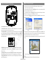
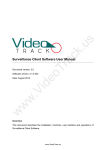
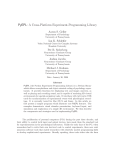
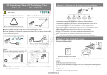
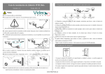
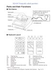
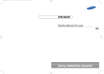
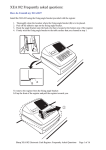
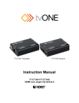
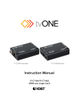
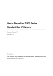
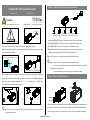
Chapter 1: Diagram for IP camera video surveillance Standard Box IPC Installation Guide Version: 1.0 Date: 2011.10 TCP/IP .u s PC Attention ► Do not connect cables when power is on! ► Please use DC 12V, currency no less than 1A. ac k DC12V/1A Microphone Detective Loudspeaker Audio input Alarm input Audio input ③ ① ② Warning lamp Remote device Alarm output RS 485 ④ ⑤ ①Internal(or external) radio collectors like microphone to realize voice collection function Do not connect cables when power is on! ②External alarm input devices like detector to realize setting up defense function on spot ► All uncovered cable should be less than 5mm, to avoid exceptional device damage. Tr ③External radio play devices like active loudspeaker to realize broadcast function ►Network cable quality will influence the communication distance. Please use repeater when exceeding ④External alarm output devices like alarming lamp to realize remote alarm linkage function network communication distance. ⑤Remote controlling camera through PTZ to realize one-in-all surveillance. Based on TCP/IP network, it is convenient to manage and control terminal devices. eo Uncovered cable should be less than 5mm id Please use repeater when exceeding 80m .V ► To install the cameras in outdoor places, please note that the protective covers shall be installed and lightning protection measures shall be taken. In particular, don’t contact the cameras in case of lightning. Notes: ①Please refer to user manual for details concerning cable interface. ②Camera lens and mounting bracket are not included in this products, and you need buy them according to the real situation. ③For other information not mentioned here, please read related user manual. Chapter 2: How to install IP camera ► Camera working environment: Temperature -20 ℃ ~ +55 ℃, humidity 10% ~ 80%RH. When w use it outside, please prepare suitable protection cover. w w Base Installation seat of lens 1. Put the self-supply lens on the installation seat of lens, and tighten the installation seat of lens onto the camera. Note: Please pay attention to above notices, otherwise the device can not work normally and even get damaged seriously. 2. Use 4 screws to fix the base on the top or bottom of the camera, according to different installation modes. 3. Put the self-supply protective cover or bracket on the camera, and fix it to complete the installation. www.VideoTrack.us Chapter 3: Introduction on cable interface Chapter 4: Network connection For the first network connection, please follow the following steps to configure your network. 1. Use cable to connect camera with computer. AIN .u s 2. When connecting with 10M network, the orange indicator will be on, when connecting with 100M PWR AOUT network, the green indicator will also be on. 3. If your computer IP address is in different gateway with that of camera, please change your computer RESET STATE IP address in the same gateway as camera, for example, 192.168.1.87. SD CARD ac k 4. In the IE browser, please input camera IP address (default IP “192.168.1.88”) and enter, then below dialog table will come out. COM NO IN GND + - DC 12V LAN 485 Tr ALARM 1. Power Interface( DC 12V ): Connect with power adaptor. eo 2. Network Interface( LAN ): Ethernet port for 10/100M. Through this port, you can connect the camera with other network devices like switcher, hub, router, etc. Picture 1 Picture 2 5. After input the user name and password (default user name “admin” and password “admin”), below recover to default configuration. Default IP address is 192.168.1.88, user name “admin” and password “admin”. activeX controls will show in the screen. This is a prerequisite activeX and controls for this application, 4. Alarm Interface (COM, NO, IN, GND): connect with external alarm input & output devices. See without any danger information. Please run it according to above picture 2. below detailed information. 6. After finish the activeX and controls installation, please refresh the web page and below picture will 485 w w A LA RM + - w COM NO IN GND come out. .V id 3. Reset Button (RESET): Long press this button for more than 30 seconds when power on, the camera will 5. RS485 Interface: Supports standard 485 PTZ protocols, for connecting with PTZ. Please see above picture. 6. Audio input (AIN) : connects with external voice collectors like microphone to realize voice collection function. 7. Audio output (AOUT): connects with external play devices like act loudspeaker to realize broadcast function. 8. SD card slot: Supports SD card local storage for video recording and snap, up to 64G(Optional). 9. Indicator (PWR, STATE): When the camera is in power on, PWR light will go on. When insert SD card, STATE light will go on. 7. If you want to change the camera IP address, please refer to the user manual. www.VideoTrack.us Note: Please adjust the IP address well first and then install the camera.