1
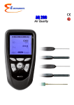
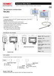
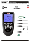
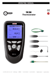
Supplied with Calibration certificate Multifunctional IAQ Monitor AMI 300 P a Table of contents 3 I – Technical specifications.............................................................................................4 Technical features..................................................................................................................................4 Specifications...........................................................................................................................................4 II – Introduction...................................................................................................................6 Description................................................................................................................................................6 Connections..............................................................................................................................................7 III – Browsing........................................................................................................................8 IV – Menus............................................................................................................................9 Probe menu...............................................................................................................................................9 Using wire probes and modules..................................................................................................................9 Using wireless probes.......................................................................................................................................9 Functions...................................................................................................................................................9 Temperature.......................................................................................................................................................9 Hold - Min/Max...........................................................................................................................................9 Delta T.............................................................................................................................................................9 Hygrometry..........................................................................................................................................................10 Calculations...................................................................................................................................................10 Air quality..............................................................................................................................................................10 Audible alarm................................................................................................................................................11 Pressure...............................................................................................................................................................11 AutoZ...............................................................................................................................................................11 Airflow....................................................................................................................................................................11 Area..................................................................................................................................................................11 Duct type...............................................................................................................................................................11 Sizes........................................................................................................................................................................11 K2 factor...............................................................................................................................................................11 Units........................................................................................................................................................................11 COmax....................................................................................................................................................................11 Air velocity............................................................................................................................................................12 Average...........................................................................................................................................................12 Point / point average.......................................................................................................................................12 Automatic average............................................................................................................................................12 Automatic point / point average................................................................................................................12 Configuration................................................................................................................................................12 Thermocouple type............................................................................................................................................12 Display....................................................................................................................................................................12 Units........................................................................................................................................................................13 Integration............................................................................................................................................................13 Compensation.....................................................................................................................................................13 Pressure system................................................................................................................................................13 Solenoid valve......................................................................................................................................................13 Parameters...................................................................................................................................................13 Language...............................................................................................................................................................13 Date / Time..........................................................................................................................................................13 Beep........................................................................................................................................................................13 Extinction..............................................................................................................................................................13 RF logging.............................................................................................................................................................13 Screen saving......................................................................................................................................................13 Backlit.....................................................................................................................................................................13 Key code................................................................................................................................................................14 Code........................................................................................................................................................................14 Using hotwire ...................................................................................................................................................................................14 Using Pitot tube...................................................................................................................................................................................14 Recording.......................................................................................................................................................14 Downloading data...................................................................................................................................15 V – General informations.................................................................................................16 Info menu...................................................................................................................................................16 Maintenance.............................................................................................................................................16 Warranty...................................................................................................................................................16 4 I – Technical specifications Technical features Sensing elements Instrument connections..........On the top : 2 secured mini-Din connectors for SMART-plus probes Pressure module Piezoresistive sensor Overpressure allowed ±500 Pa : 250 mbar Overpressure allowed ±2,500 Pa : 500 mbar Overpressure allowed ±10,000 Pa : 1,200 mbar Overpressure allowed ±500 mbar : 2 bar Overpressure allowed ±500 mbar : 2 bar Hotwire: Thermistance with a negative temperature coefficient Ambient temperature : Pt100 1/3 Din. Ø 70 and 100 mm vane probes : Hall effect sensor Ambient temperature : Pt100 class A. Ø 14 mm vane probe: Proximity sensor Ambient temperature : Pt100 class A. Hygrometry/Temp. probes: capacitive sensor Pt100 1/3 DIN Thermocouple probes : type K, J and T class 1 Smart-plus Pt100 probes : Pt100 class 1/3 Din Climatic conditions module: Hygrometry : capacitive sensor Temperature : semiconductor sensor Air pressure : piezoresistive sensor Left side : 1 USB port for E Instruments cable only 1 power supply plug Modules connections.................Thermocouple 4 inputs for compensated miniature plug of thermocouple K, J or T type Class 1 (as per IEC 584-3) Pressure 2 pressure connectors Ø 6,2 mm made of nickel brass 2 threaded pressure connectors Ø 4,6 mm made of nickel brass (for 500 and 200 mbar) + 1 temperature thermocouple input for miniature connector current/Voltage module 2 stereo jacks Display.........................................Graphic display 320x240 pixels Dim. 70 x 52 mm. Color display Display of 6 measurements (including 4 simultaneously) Housing........................................ABS shock-proof, IP54 Keypad.........................................Metal-coated, 5 keys, 1 joystick Conformity...................................electromagnetic compatibility (as per NF EN 61326-1) Power supply..............................4 alcaline batteries 1,5V LR6 Operating environment..............Neutral gas Operating temperature...............from 0 to 50°C Storage temperature..................from -20 to +80°C Auto shut-off...............................adjustable from 0 to 120 min Weight..........................................380g Languages...................................French, English, and others coming soon. Please contact us Air quality probes CO2 : NDIR sensor CO : electrochemical sensor Temperature : Pt100 class A Hygrometry : capacitive sensor Climatic conditions module: Hygrometry : capacitive sensor Temperature : semiconductor sensor Air pressure : piezoresistive sensor Multifunction probe Air velocity : Thermistance with a negative temperature coefficient Hygrometry/Temp.: Capacitive sensor, Pt100 1/3 DIN Tachometry sensor Optical : optical sensor Contact : optical probe with ETC adaptor Specifications Measuring range Measuring units PRESSURE From From From From From Pa, mmH 2 O, In WG, mbar, hPa, mmHg, DaPa kPa, bar, PSI 0 0 0 0 0 to to to to to ±500 Pa ±2,500 Pa ±10,000 Pa ±500 mbar ±2000 mbar Accuracy* ± 100 Pa : ±0.2% of reading ±0.8Pa, bey ond ±0.2% of reading ±1,5Pa, ±0.2% of reading ±2Pa ±0.2% of reading ±10Pa ±0.3% of reading ±0.5mbar ±0.3% of reading ±2mbar Resolutions 0.1 Pa from -100 to +100 Pa, 1 Pa beyond 1Pa 1Pa 0,1mbar 1mbar CURRENT / VOLTAGE From 0 to 2,5 V From 0 to 10 V From 0 to 4/20 mA V, mA ±2mV ±10mV ±0.01mA 0.001 V 0.01 V 0.01 mA THERMOCOUPLE °C, °F + K: J: T: From -200 to +1300°C From -100 to +750°C From -200 to +400°C ±1,1°C or ±0.4% Reading value** ±0.8°C or ±0.4% Reading value** ±0.5°C or ±0.4% Reading value** 0.1 °C 0.1 °C 0.1 °C CLIMATIC CONDITIONS Hygro. Temp. %RH °C, °F hPa From 5 to 95%RH From -20 to +80°C From 800 to 11,00 hPa See datasheet interchangeable measurement modules 0.1 %RH 0.1 °C 1 hPa 5 I – Technical specifications Measuring units Measuring ranges Accuracy* Resolutions HOTWIRE - Standard and telescopic Air velocity 0.1 °C ±3% of reading ±0.1m/s ±1% of reading ±0.3m/s 0.01 m/s 0.1 m/s From -20 to +80°C ±0.4% of reading ±0.3°C 0.1 °C From 0 to 99999 m 3 /h ±3% of reading ±0.03*area (cm 2 ) 1 m3/h From -20 to +80°C m /h, cfm, l/s, m /s 3 m/s, fpm, Km/h °C, °F Temperature Airflow ±0.3% of reading ±0.3°C ±3% of reading ±0.03*area (cm 2 ) °C, °F 3 Ø 100 mm VANE PROBE Air velocity 0.01 m/s 0.1 m/s From 0.15 to 3 m/s From 3.1 to 30 m/s Temperature Airflow ±3% of reading ±0.03 m/s ±3% of reading ±0.1 m/s m/s, fpm, Km/h m /h, cfm, l/s, m 3 /s 3 From 0 to 99,999 m / h 3 From 0.25 to 3 m/s From 3.1 to 35 m/s 1 m3/h Ø 70 mm VANE PROBE Air velocity m/s, fpm, Km/h From 0.3 to 3 m/s From 3.1 to 35 m/s ±3% of reading ±0.1m/s ±1% of reading ±0.3m/s 0.1 m/s Temperature °C, °F From -20 to +80°C ±0.4% of reading ±0.3°C 0.1 °C From 0 to 99,999 m 3 /h ±3% of reading ±0.03*area (cm 2 ) 1 m3/h From 0.8 to 3 m/s From 3.1 to 40 m/s ±3% of reading ±0.1m/s ±1% of reading ±0.3m/s 0.1 m/s From 0 to 99,999 m 3 /h ±3% of reading ±0.03*area (cm 2 ) From -20 to +80°C ±0.4% of reading ±0.3°C 0.1 °C From 2 to 5 m/s From 5,1 to 100 m/s From 0 to 99,999m3/h ±0.3 m/s ±0.5% of reading ±0.2m/s ±0.2% of reading ±1% PE 0.1 m/s m/s, fpm, Km/h, mph From 4 to 20 m/s From 21 to 100 m/s ±0.3 m/s ±1% of reading ±0.1m/s 0.1 m/s 0.1 m/s m 3 /h, cfm, l/s, m 3 /s From 0 to 99,999m3/h ±0.2% of reading ±1% PE 1 m3/h From From From From See related datasheet « Portable probes » 0.1 °C 1 ppm 1 ppm Airflow m 3 /h, cfm, l/s, m 3 /s Ø 14 mm VANE PROBE Air velocity Airflow Temperature m/s, fpm, Km/h m 3 /h, cfm, l/s, m 3 /s °C, °F 1 m3/h PITOT TUBE Air velocity Airflow m/s, fpm, Km/h, mph m 3 /h, cfm, l/s, m 3 /s 1 m3/h DEBIMO BLADES Air velocity Airflow AIR QUALITY PROBES: CO / CO2 / Temperature / Hygrometry Temperature CO 2 CO Relative humidity °C, °F ppm ppm %RH -20 to +80°C 0 to 5,000 ppm 0 to 1,000 ppm 5 to 95%RH 0.1 %RH HYGROMETRY PROBES STD Relative humidity Absolute humidity / enthalpy Dew point Ambient temperature %RH g/Kg / Kj/Kg °C td , °F t d °C, °F From 3 to 98 %RH See related datasheet « Portable probes » From -50 to +80°C t d From -20 to +80°C ±0.6% of reading ±0.5°C t d From 3 to 98 %RH See related datasheet « Portable probes » From -50 to +80°C t d From -40 to +180°C ±0.6% of reading ±0.5°C t d According to hygrometry and temperature meas uring ranges ±0.3% of reading ±0.25°C 0.1 %RH 0.1 g/Kg 0.1 °Ctd 0.1 °C HYGROMETRY PROBES H.T Relative humidity Absolute humidity / enthalpy Dew point Ambient temperature %RH g/Kg / Kj/Kg °C t d , °F t d °C, °F Ac cording to hygrometry and temperature measuring ranges ±0.3% of reading ±0.25°C 0.1 %RH 0.1 g/Kg 0.1 °Ctd 0.1 °C TACHOMETRY Probe (see datasheet «portable probes») MULTIFUNCTION Probes (see datasheet «portable probes») Pt100 Smart-Plus Probes (see related datasheet) *All accuracies indicated in this document were stated in laboratory conditions and can be guaranteed for measurements carried out in the same conditions, or carried out with required compensation. ** The accuracy is expressed either by a deviation in °C or by a percentage of the value concerned. Only the bigger value is considered. 0.01 °C II – Introduction 6 Description Top view Module connections Graphic display Battery level Mini-Din C2 connector mini-Din C1 connector Memory status used Hour Value Unit Side view Power supply connection Channel USB port for E Instruments cable Circular menu Elastomer protection Keypad Access keys for circular menu Browsing joystick : ● 4 directions ● Validation Escape key On/Off key II – Introduction 7 Connections Interchangeable measurement modules Interchangeable modules with Smart-plus system are automatically recognized when connected to the instrument. 1. Current / voltage module 2. Pressure module It allows current or voltage measurements on V/ A1 or VA/2 channels with current/voltage input cables or ammeter clamps. It allows differential pressure, air velocity or airflow measurements with Pitot tube or Debimo on two pressure inputs (- and +) and thermocouple temperature measurement on Tc1 channel with wire thermocouple probes equipped with a miniature male connector. 3. Thermocouple module 4. Climatic conditions module It allows thermocouple temperature measurement on Tc1, Tc2, Tc3 and Tc4 channels with type K, J or T with wire thermocouple probes equiped with a miniature male connector. It allows hygrometry measurement on Hygro channel, ambient temperature measurement on Ptx channel and air pressure on PATM channel. Wire probes with Smart plus system Wire probes with Smart-plus system are automatically recognized when connected to the instrument. Probes are connected on min-DIN connectors C1 and / or C2 mini-Din C2 connector Mini-Din C1 connector Secured Mini-Din Connector Non-exhaustive list of probes Wireless probe/instrument communication Wireless communication between probe and instrument with automatic recognition after power-up. Hygrometry probes or Pt100 probes are displayed on hygro, Tr1 or Tr2 channels followed by wireless communication Non-exhaustive list of probes Wireless probes shall be located near the instrument for initial recognition. Connection between AMI300 and wireless probes must be established. See submenu ''Wireless probes'' p 9. III – Browsing 8 Power-up Enter key code with directional pad. (if the locking is activated) and e Probe connection Probes display Select a connection with right and left keys Connections can be activated or deactivated with or Info Measure Params Select a sub menu with access keys Measurement Measurement display Return to previous screen Sub menus appears according to probes type. Select sub menu with arrows keys or access keys Communication interrupted Check probes connection IV – Menus 9 Probe menu 1. Using wire probes and modules Wire probes and modules with Smart-plus system are automatically recognized from first connection. The ''Probe'' menu only appears when probes or module are connected. This menu allows to view probe information plugged to C2, Module, C1 or wireless connections. (See « Connections » p 7 for more information about connections). Probes display Available information are : • Sensor type, Serial number, Date of last calibration or adjustement, Probes Status (enabled ou disabled). On enabled mode, the probe is connected, the measurement is carried out and the value is displayed. On disabled mode, the probe is connected, the measurement is not carried out and the value is not displayed. Info 2. Using wireless communication A- Add a wireless probe A1. Go to probe menu by pressing ''Probe'' access key. A2. With arrow keys and , go to ''RF probes'' display. A3. Select New with access key. A4. Power up the probe and press multifunction button until LED blinks. Once the probe is recognized, information appears. Left button allows to return to the RF probes display and to access all RF probes already recognized by the instrument. With access keys, it is possible to delete ( Del) a RF probe. B- Select a wireless probe already created. B1. Power up the RF probe (short press on Multifunction button). B2. Go to ''Probe'' menu. B3. With arrows keys and , go to ''RF probes'' Display. All the RF probes already recognized appear. B4. Select the suitable RF probe with or . B5. Go to probe informations using arrow key . B6. Enable the RF probe with arrows keys and and confirm with OK . Measure Params RF probes display RF probes RF probes searching RFprobes probesHygro detected RF Std 3 RF probes display RF probes Functions Temperature The following functions are enabled only if at least one probe is connected. - Hold (Hold - Min/Max) - Config (Configuration) - see Air velocity - ∆ T (Delta T) - Alarms - see Air quality - Rec (Recording) - see Air velocity - Params (Parameters) - see Air velocity Hold / Min-Max Press 1x in order to select HOLD function : measurement holding on display. Press 2x in order to select Min-Max function : display of minimum and maximum values. Press 3x : back to the continuous measurement. Delta T When two PT100 probes or 2 thermocouple temperature probes are connected, AMI300 can calculate Delta temperature value : the temperature difference between C2 and C1, or T2 and T1, or T4 and T3. Select Delta T in order to view the temperature difference. If you select Delta T again, Delta T function is disabled. 10 IV – Menus Hygrometry The following functions are enabled only if at least one probe is connected: - Hold (Hold – Min/Max) – see Temperature - Config (Configuration) - see Air velocity - ∆ T (Delta T) - Calc. (Calculation) - Alarms - see Air quality - Rec (Recording) - see Air velocity - Params (Parameters) - see Air velocity Calculations Press the access key Calc. . Press in order to enter in the submenu and choose calculation type (none, psychrometer or WGBT) by means of arrows keys and . Confirm with OK. Select Esc to quit this menu. • Psychrometer Wet Temperature (Tw) is the temperature at which water evaporated into the air brings the air to saturation at the same temperature. It is expressed in Celsius degree . Absolute humidity (ρV) is the ratio between the mass of water vapor present to the mass of dry gas. It is expressed in grams of water vapor per kiRecrams of dry gas. Dew-point temperature (Td): is the temperature to which the air must be cooled, at constant barometric pressure for water vapor to condense into water. It is expressed in Celsius degree. Contact dew-point temperature (Td) is the dew point temperature measured by a PT100 contact probe. It is expressed in Celsius degree. Specific enthalpy (i) is the total heat contained in 1 kg of wet air. It is expressed in kJ/kg. ● WBGT index (Wet bulb globe temperature). For hygrometry probe coupled with black ball thermometer. If WBGT index is selected, press then OK or and a list appears. Select Inside or Outside with arrow and . Confirm with OK. The WBGT, described as per ISO 7243, allows an evaluation of working climatic conditions. Outdoors, the following formula is used: WBGT outside = 0.7 Thn + 0.2 Tg + 0.1 Ta Indoors, It is calculated from the following formula : WBGT inside = 0.7 Thn + 0.3 Tg where: - Thn is the natural wet temperature, - Tg is the temperature measured with a black ball thermometer - and Ta is the ambient temperature. Air quality The following functions are enabled only if at least one probe is connected: - Hold (Hold – Min/Max) – see Temperature - Config (Configuration) - see Air velocity - ∆ T (Delta T) – see Temperature - Calc. (Calculation) – see hygrometry - Alarms - Rec (Recording) - see Air velocity - Params (Parameters) - see Air velocity IV – Menus 11 Alarms Select respectively ON or OFF with and in order to enable or disable the alarm. Choose your setpoint : CO Limit 1 (first CO setpoint), CO Limit 2 (second CO setpoint), low temperature setpoint and high temperature setpoint. Confirm with OK or . Select thresholds with OK or to enter CO and temperature setpoints. Select + or – signs with and then pass on the first digit with . Low and high thresholds entered, confirm with OK . Pressure Access Pressure function by means of Pressure key. With Pressure function, you can access to following sub-functions - Hold – see Temperature - Config. (Configuration) - see Air velocity - Params (Parameters) - see Air velocity - Avg. (Average) - see Air velocity - Rec (Recording) - see Air velocity AutoZ This sub-function allows to compensate for any long-term drifts of the sensing element by a manual adjustment of the zero. For the ±500 Pa measurement module, self-calibration is performed by the solenoid valve. Once pressing Autoz key, the zero is readjusted. This function can also be automatically performed by using the solenoid valve function. For others measurement modules, self-calibration is performed by disconnecting the two pressure inlets of the sensor, then by pressing Autoz key. Airflow Access Airflow function by means of Air flow key. With Airflow function, you can access to following sub-functions - Hold – see Temperature - Area - Config. (Configuration) - see Air velocity - Params (Parameters) - see Air velocity - Avg. (Average) - see Air velocity - Rec (Recording) - see Air velocity Area • Type To select vent Type press OK or . Select Lx W or Diam or K factor with arrow buttons and . Confirm with OK. If K factor is selected, you must enter value. You can choose a K factor already registered by selecting with and . Confirm with OK. This factor can be modified by selecting with and , then confirm with OK or . Select Modify with OK or . Enter factor by means of arrow keys and . Confirm with OK or . • Sizes Press or OK to enter into sizes sub function. You can choose an air vent already registered by selecting it with arrow keys and . Confirm with OK or . This air vent can be modified by selecting it with arrows keys and , then Confirm with OK or . Select Modify with OK or . Enter sizes by means of arrow keys and . Confirm with OK or . • K2 factor Press or OK to enter into the K2 factor sub function. Select respectively ON or OFF with and in order to enable or disable this function. Confirm with OK . • Units To select the unit press OK or . Select mm or in with arrow buttons and . Confirm with OK. IV – Menus 12 CO max The CO mode is available when a CO/Temperature probe is connected. You can access this function selecting COmax with the access key CO max The CO is measured on an adjustable period, the maximum value measured in this period is called CO max . When CO peak is selected, the period is diplayed (30 seconds by default). Press Valid. to launch the measurement. When the countdown is finished, the CO max is displayed. To modify the period, press Period with the access key. Modify time with arrows keys and . Confirm with OK or . Air velocity Access Air velocity function by means of Air velocity key. With Air velocity function, you can access to following sub-functions - Hold – see Temperature - Config. (Configuration) - Params (Parameters) - Avg. (Average) - Rec (Recording) Average Press or OK to enter Average sub function. With and , you can select : point/point average, auto, point/point automatic. Confirm with OK or . • Point / point average This function allows to calculate the average value of various points that you can select. Numbers of selected points and parameter for which calculation is carried out, are displayed For adding a new measuring point to this calculation, press OK to confirm. If you click on average icon, max. and min. values, standard deviation, average of each channel and e numbers of measuring points will be displayed. If you want to see all values, select Visu. and scroll with and . • Automatic average This function allows to calculate an average value that the device measured in an interval chosen time. Timer is displayed. Select Start with access key for launching measurement. If you click on average icon, max. and min. values, standard deviation, average of each channel and time chosen will be displayed. • Automatic point/point average This function allows to calculate the average value of various points, calculated themselves on a duration beforehand defined. You must enter duration : click on the Period icon. Select minutes or seconds with arrow buttons and . Scroll digits with and . Confirm with OK. The numbers of points is displayed. Press Ok for launching measurement. If you click on average icon, max. and min. values, standard deviation, average of each channel and numbers of measuring points will be displayed. You can view each measuring points if you click on Visu. Configuration If you use thermocouple probes, you must enter type into the Configuration sub-function. Configuration sub-function allows to: •Select thermocouple type Click on OK or to enter into sub function : a list of thermocouple available ( K, J or T type) appears . Select type with and . Confirm with OK. • Select display Click on OK or to enter into sub function. Select channel or display type required (Digital, Bargraphs or Curves) with and . Confirm with OK. Select the configuration of display required. IV – Menus 13 • Select units Click on OK or to enter into sub function : a list of units available appears. Select unit required with and . Confirm with OK. Click on Esc to return to previous screen. • Select integration The coefficient of integration allows to smooth the measure, to avoid variations. Click on OK or to enter into sub function : a list of coefficient (From 0 to 9) appears. Select coefficient required with and . Confirm with OK. Coefficient 0: no integration, important fluctuation in the shown measure. • Select compensation It is possible to modify the value of the compensation in temperature. Indeed, the velocity and the airflow with Pitot's tube and with Debimo blades are calculated from a temperature of use in +20°C. It is thus necessary to enter the real temperature of use to obtain more precise results. Click on OK or to enter into the sub function. Select + or – signs with and with and then pass on the first digit with . enter the first digit then move to the next one with . Confirm with OK. • Select airflow system (only available for Air velocity and Airflow functions)Click on OK or to enter into sub function : a list of air flow systems available appears (Pitot tube L, S, Debimo or Other).Select your system with and . Confirm with OK. If Other is selected, you must enter a value. Click on OK or to enter into sub function. With and , enter the first digit then move to the next one with . Confirm with OK. •Solenoid valve (available with the ± 500 Pa module) Click on OK or to enter into the sub function. Select respectively ON or OFF with and in order to enable or disable the solenoid valve function. Confirm wih OK or . When the solenoid valve is enabled, it runs every minute. Parameters • Language Click on OK or to enter and a list of languages available appears. Select language with arrow keys and and Confirm wih OK. • Date / Time Click on OK or to enter into sub function. Enter the day with and then move to the next digit with . Repeat this operation for the month, year, hour and minute. Confirm wih OK. • Beep This sub-function allows to enable or disable the keypad beep. Click on OK or to enter into the sub function. Select respectively ON or OFF with and in order to enable or disable the beep. Confirm wih OK. • Extinction This sub-function allows to enable the automatic shut-off and to select the delay in minute. Click on OK or to enter into the sub function. Select, with and , OFF in order to disable the automatic shut-off or enter the delay (from 15 to 120 minutes). Confirm wih OK. • RF Logging This sub-function allows to enable or disable the RF Recording. Click on OK or to enter into the sub function. Select respectively ON or OFF with and in order to enable or disable this function. Confirm wih OK. • Screen Saving This sub-function allows to enable or disable the screen saving. Click on OK or to enter and a list appears. Enter the delay before the sreen saving activation with and Confirm wih OK. • Backlit This sub-function allows to modify the backlit. Click on OK or to enter. Select your backlit level (from 0 to 9 or AUTO) with and . Confirm wih OK. If you select AUTO, the AMI 300 adjuts automatically the backlit according to the room brightness. IV – Menus 14 • Key locking This sub-function allows to enable or disable the key lock. Click on OK or to enter into sub function. Select respectively ON or OFF with and in order to enable or disable this function. Confirm wih OK. If the locking is enabled, the code menu appears • Code This sub-function allows to enter the security code. Click on OK or and the code appears. Enter the first digit of the code with and then move to the next one with . Confirm wih OK. Using a hotwire 1. Connect the hotwire probe to AMI 300. Probe menu appears. 2. Slide down protection tube. 3.The probe must be perpendicular to airflow : the red point at the bottom of the probe must face airflow. 4. Press OK to enter in the Measure menu, the air velocity and temperature values are displayed. Sensing element (air velocity) Sensing element (temperature) Airflow direction Tube protection Red point Using Pitot tube 1. Connect the pitot tube to AMI 300. 2. The probe must be placed at the center of the duct and parallel to the air flow. 3. Press OK to enter in the Measure menu, the air velocity and temperature values are displayed on the screen. (-) Static pressure PS (+) Total pressure PT - + Dynamic pressure = PT - PS Recording The Recording menu allows a measurement dataset. You can choose between a planned or a continuous dataset. Memory capacity of the instrument is up to 12,000 measurement points or 50 datasets. 1. Create or launch a continuous dataset A continuous dataset can be carried out using AMI 300 and is composed of several dated measuring points. The operator can choose an automatic or a manual dataset, with an instant value or an average. This datasets can't be set using Datalogger-10 Software. 1.1 Manual dataset A manual dataset is composed of measuring points selected by the operator. a. Click on OK or to enter into sub function. b. Select Manual with and . Confirm wih OK. c. Select Name with and . Confirm wih OK or . Enter dataset name with arrow keys and e. Confirm wih OK. d. For measurement launching, click on OK with the access key. The number of points selected and the parameter are displayed. e. To save your dataset click on Save with the access key. 1.2 Automatic dataset An automatic dataset is composed of measuring points with interval of time. a. Click on OK or to enter sub function. b. Select Auto. with and . Confirm wih OK. c. Select Name with and . Confirm wih OK or . Enter dataset name with the arrow keys and e. Confirm wih OK. d. Enter dataset time and interval of time between 2 measurement by selecting Period with access key. Select Duration or Interval with and . Confirm wih OK. Enter minutes and seconds with arrow keys and ( from 1 minutes to 24 hours for the duration and from 5 seconds to 10 minutes for the interval). Confirm with OK. e. Select Start for dataset launching. IV – Menus 15 2. Launch a planned dataset A planned dataset is composed of several locations. For each location, the operator can enter a theorical value and a tolerance for the parameter to be controlled. Planification must be made via the software. a. Click on OK or to enter into sub function. b. Select Planned with and . Confirm wih OK. c. Choose dataset name with and . Confirm wih OK. d. Select the location with and . Confirm wih OK. 3. Preview of dataset graphic You can display a graph of datasets performed on the device. Dataset summary a. Go to Recording menu. b. Select Display. Click on OK to validate. c. Select dataset name with arrow keys and . Click on OK. Summary screen of selected dataset is displayed. From this screen, you can : ● Select other dataset using arrow keys and . ● Dislplay data of other channels using arrow keys and . Dataset graph d. Click on OK to display selected dataset graph. From this screen you can : ● Browse on the curve with arrow keys and to display values of pionts. ● Select the channel using arrow keys and . Note : if selected dataset has more than 180 points, the device will display a global view of dataset. To zoom on a dataset part, use arrow keys and press key. The device displays graph of the interval of selected points. 4. Delete all datasets Select Delete with and . Confirm wih OK. Downloading data see DataLogger-10 user manual chapter III – Read device page 6. Global graph of dataset V – General information 16 Info menu This menu allows to view the serial number of instrument and firmware version. Battery When battery indicator flashes it is recommended to change the batteries: 1. Remove the front part at the back of the instrument. 2. Remove batteries 3. Insert new batteries (AA-LR6 1,5V) in accordance with proprer polarity drew inside the housing. 4. Replace the front. Maintenance E Instruments performs calibration, adjustment and maintenance of all your instruments to guarantee a constant level of quality of your measurements. In regards of Quality insurance norms, we recommend that the instruments are checked once a year. E Instruments Instruments have 1-year guarantee for any manufacturing defect (return to our After-Sales Service required for appraisal). E Instruments International LLC 172 Middletown Blvd - Suite B201 Langhorne, PA 19047 Tel.: 215 750 1212 Fax: 215 750 1399 E-mail: [email protected] Web: www.E-Inst.com Distributed by: NTang – AMI 300 – 02/09 D – We reserve the right to modify the characteristics of our product. Warranty