1
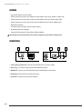
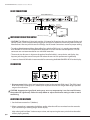
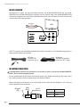
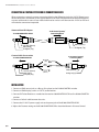
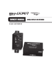
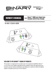
OWNER’S MANUAL
B-300-HDMATRIX-RCVR
BINARY SINGLE CAT 5E/6 HDMI 1.4
EXTENDER FOR USE WITH
B-300 HDMATRIX SERIES SWITCHERS
B-300-HDMATRIX-RCVR Installation and Users Manual
IMPORTANT SAFETY INSTRUCTIONS
WARNING: To reduce the risk of fire or electric shock, do not expose this apparatus in or near rain or moisture.
1. Read and follow all instructions and warnings in this manual. Keep for future reference.
2. Do not install near any heat sources such as radiators, heat registers, stoves or other apparatus
(including amplifiers).
3. Do not install the unit near water or where moisture is present.
4. Clean with a dry cloth.
5. Unplug this apparatus during lightning storms or when unused for long periods of time.
6. Protect the power cord from being walked on or pinched particularly at plug, convenience receptacles,
and the point where it exits from the apparatus.
7. Refer all servicing to qualified service personnel. Servicing is required when the apparatus has been
damaged in any way, such as when the power-supply cord or plug is damaged, liquid has been spilled
or objects have fallen into the apparatus, the apparatus has been exposed to rain or moisture, does not
operate normally, or has been dropped.
8. To completely disconnect this equipment from the AC mains, disconnect the power supply cord plug
from the AC receptacle.
CAUTION
CAUTION: TO REDUCE THE RISK OF
ELECTRICAL SHOCK.
DO NOT REMOVE COVER. NO USER
SERVICEABLE PARTS INSIDE.
REFER SERVICING TO QUALIFIED
SERVICE PERSONNEL.
The lightning flash with arrowhead symbol, within an
equilateral triangle, is intended to alert the user to the
presence of un-insulated dangerous voltage within the
product’s enclosure that may be of sufficient magnitude
to constitute a risk of electric shock to persons.
The exclamation point within an equilateral triangle is
intended to alert the user to the presence of important
operating and maintenance (servicing) instructions in the
literature accompanying the appliance.
OVERVIEW
The B-300-HDMATRIX-RCVR extends HDMI from a B-300-HDMATRIX series switcher over single Cat5e/6
130 feet at 1080P60 24Bit color,t including all HDMI 1.4a 3D formats.
PACKAGE CONTENTS
• (1) B-300-HDMATRIX-RCVR
• (1) +5V 4A DC power supply
• (1) User manual
• (1) IR Adapter
pg.2
B-300-HDMATRIX-RCVR Installation and Users Manual
FEATURES
• Support for HDMI 1.4a 3D formats
• Extends the transmission up to 200 ft. from the HDMI source at HD 1080i or 720p 24-Bit
• Extends the transmission up to 130 ft. from the HDMI source at Full HD 1080p 24-Bit
• Extends the transmission up to 65 ft. from the HDMI source at Full HD 1080p 36-Bit
• HDCP 2.0 compliant
• DTS-HD Master and Dolby TrueHD audio support
• Bi-directional IR pass-through
• Supports full-frequency IR signal from 20kHz to 60kHz
See Important Connection Notes! for cautions regarding connection and operation.
CONNECTIONS
1
2
3
1. Latch-locking power jack: Connect to included 5V 4A DC power supply.
2. RJ45: Plug in a Cat5e/6 cable from B-300-HDMATRIX Output.
3. HDMI OUT: Connect to an HDMI display with a HDMI male-to-male cable.
4. IR Receiver: Infrared 3.5mm jack for IR receiver.
5. IR Flasher: Infrared 3.5mm jack for IR flasher
pg.3
4
5
B-300-HDMATRIX-RCVR Installation and Users Manual
BASIC CONNECTIONS
B-300-HDMATRIX-4x4
Cat5e/Cat6 (Shielded Recommended)
IR Receiver
B-300-HDMATRIX-RCVR
HDTV
IMPORTANT CONNECTION NOTES!
HDMI cable (1m max length)
• CAUTION: The IR Receiver 3.5mm jack provides 12V power for IR receivers that can damage flashers and
control systems. Check carefully before plugging an IR Flasher or IR Receiver into the respective IR sockets.
Manufacturer’s Warranty will not cover the damage. See IR Control Connections section for proper cabling.
• To reduce video dropout problems from ceiling fans and other EMI issues, it is strongly recommended
that shielded CAT5e/CAT6 and shielded RJ45 connectors are used with this extender product. “EZ-end”
connectors are not recommended for use with HDMI extenders.
• The transmission distance is subject to the grade of installed cable(s), source device, and display. Any
keystone jack along the transmission path will reduce the transmission performance significantly
• 1 meter or shorter HDMI cable is recommended for connecting the B300-HDMATRIX-RCVR to the display.
CALIBRATION
1
1. Distance control: Adjust the 8-level equalization control to the received HDMI signals. The HDMI signal
level varies from 0 (strongest) to 7 (weakest) for respective transmission length from longest possible
range to short distance.
CAUTION: Inappropriate signal level setting may cause an overpowering issue that would shorten
the product life significantly. Follow the steps below to adjust the distance setting in order to avoid
overdriving.
ADJUSTING FOR DISTANCE
1. Set the distance control to 7 (Weakest).
2. Select a source that is outputting the highest-quality video that will be transmitted over the extender.
If you see flickering or blinking images on the display:
pg.4
Adjust the signal level from 7 to 0 one step at a time, and stop turning the rotary switch when the audio/
video is playing normally.
B-300-HDMATRIX-RCVR Installation and Users Manual
IR PASS-THROUGH
Bi-directional IR signals are also transmitted between the B-300-HDMATRIX-RCVR and the B-300HDMATRIX-4x4 or B-300-HDMATRIX-8x8 switchers over the Cat5e/6 cable. Each B-300-HDMATRIX-RCVR
will need an IR Receiver to send IR from the RCVR to the switch, and an IR flasher to use IR sent from the
switch to the RCVR (sold separately).
IR Receiver
HDTV
NOTE: This product was specifically engineered for Episode® IR products. Use of the following products is
highly recommended (not included):
IR Receiver
(Episode® IR-SM-3660
or Episode® IR-TT-3660)
IR Flasher
(Episode® IRF-1
or Episode® IRF-2)
IR CONTROL CONNECTIONS
CAUTION: Before connecting an IR Receiver or an IR control system, verify that the B-300-HDMATRIXRCVR is OFF to avoid damaging the unit.
Pin out configurations for IR receivers and control systems vary. Before connecting to this input, review
this section carefully in order to match the pin outs for the HDMatrix.
Before connecting an IR Receiver or to an IR control system, verify that the HDMatrix is OFF to ensure
proper operation when connected.
IR Signal
(Tip)
pg.5
GND
(Ring)
12v DC
(Sleeve)
IR Signal
Tip
GND
12v DC
Ring
Sleeve
B-300-HDMATRIX-RCVR Installation and Users Manual
CONNECTING A CONTROL SYSTEM OR IR CONNECTING BLOCK
When connecting a control system or connecting block to the IR Receiver jack, the 12V DC (Sleeve) must
not be connected. Connections of this type require the use of the included Stereo to Mono IR Adaptor or
a custom cable made. A mono 3.5mm cable should not be used as it will short out the 12 VDC to GND and
will make the connection inoperable.
Stereo to Mono IR Adaptor
To IR Control System/
Connecting Block
To B-300-HDMATRIX-RCVR
GND (Sleeve)
IR Signal (Tip)
12V DC (Sleeve)
GND (Ring)
IR Signal (Tip)
Custom Cable Construction
To B-300-HDMATRIX-RCVR
IR Signal
(Tip)
GND
(Ring)
12V DC (Sleeve)
GND (Ring)
IR Signal (Tip)
To IR Control System/
Connecting Block
(Tip)
(Sleeve)
12V DC
(Sleeve)
GND (Sleeve)
IR Signal (Tip)
INSTALLATION
1. Connect a HDMI source (such as a Blu-ray Disc player) to the B-300-HDMATRIX switcher.
2. Connect a HDMI display (such as a LCD TV) to the receiver.
3. Connect IR Flasher/Receiver as needed to the receiver-300-HDMATRIX-RCVR and he B-300-HDMATRIX
switcher.
4. Connect a Cat5e/6 cable between the units.
5. Connect the 5V 4A DC power supply unit to the power jack of the B-300-HDMATRIX-RCVR.
6. Adjust the Distance setting on the B-300-HDMATRIX-RCVR as described above in Distance Control.
pg.6
B-300-HDMATRIX-RCVR Installation and Users Manual
SPECIFICATIONS
Technical
HDMI Compliance
HDCP Compliance
Video Bandwidth
Video Support
HDMI over UTP Transmission
(24-bit)
Audio Support
Distance Control
Signal Input
HDMI Output
IR PassThrough
Type:
Carrier
frequency:
IR Receiver
IR Flasher
Mechanical
Housing
Dimensions (L x W x H)
Weight
Power Supply
Power Consumption
Operation Temperature
Storage Temperature
Relative Humidity
Certifications
Full HD 1080P60, Deep Color
(36bit), 3D (1.4a)
Yes
Single-link 225MHz (6.75Gbps)
1080p / 1080i / 720p /480p / 480i up
to 36-bit color
Full HD (1080p)-130ft (CAT5e) /
165ft (CAT6)
HD (720p/1080i)- 165ft (CAT5e) /
200ft (CAT6)
Surround sound (up to 7.1ch) or
stereo digital audio
8-level control
1x RJ45
1x HDMI Type A
Bi-directional
20-60kHz
3.5mm Stereo (powered)
3.5mm Mono (unpowered)
Metal enclosure
2.9” x 3.5” x 1”
1.1 lbs
5V 4A DC
3 Watt (max)
32~104°F
-4~140°F
20~90% RH (no condensation)
CE,FCC,RoHs
WARRANTY
Two-Year Limited Warranty
This Binary™ product has a 2-year limited Warranty. This warranty includes parts and labor repairs on all
components found to be defective in material or workmanship under normal conditions of use. This warranty
shall not apply to products which have been abused, modified or disassembled. Products to be repaired under this
warranty must be returned to SnapAV or a designated service center with prior notification and an assigned return
authorization number (RA).
pg.7
© 2011 Binary
111215