1
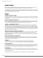
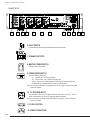
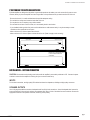
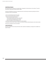
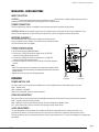
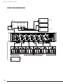
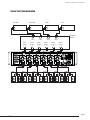
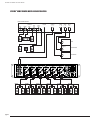
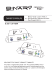
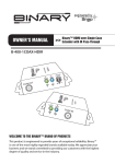
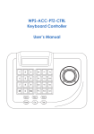
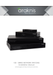
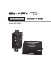
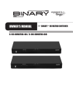
®
OWNER’S MANUAL
EA-AMP-12D-70A
12 CHANNEL
Multi-Channel, Class D,
>> 70 Watt Amplifier
EA-AMP-8D-70A
8 CHANNEL
EA-AMP-70 Installation and Users Manual
IMPORTANT SAFETY INSTRUCTIONS
WARNING: To reduce the risk of fire or electric shock, do not expose this apparatus in or near rain or moisture.
1. Read the following instructions carefully.
2. Keep manual for future reference.
3. Heed all warnings.
4. Follow all instructions in this manual.
5. Do not use this apparatus near water.
6. Clean only with a dry cloth.
7. Do not block any ventilation openings. Install according to manufacturer’s instructions.
8. Do not install near any heat sources such as radiators, heat registers, stoves or other apparatus
(including amplifiers) that produce heat.
9. Do not override the safety purpose of the polarized or grounding-type plug. A polarized plug has two blades one wider than the other. A grounding type plug has two blades and a third grounding prong. The wide blade
or the third prong is provided for your safety. If the provided plug does not fit into your outlet, consult an
electrician for replacement of the obsolete outlet.
10. Protect the power cord from being walked on or pinched particularly at plug, convenience receptacles, and
the point where it exits from the apparatus.
11. Only use attachments/accessories specified by the manufacturer.
12. Use only with a cart, stand, tripod, bracket or table specified by the manufacturer,
or sold with the apparatus. When a cart is used, use caution when moving the
cart/apparatus combination to avoid injury from tip-over.
13. Unplug this apparatus during lightning storms or when unused for long periods of time.
14. Refer all servicing to qualified service personnel. Servicing is required when the apparatus has been damaged
in any way, such as when the power-supply cord or plug is damaged, liquid has been spilled or objects have fallen into the apparatus, the apparatus has been exposed to rain or moisture, does not operate normally, or has
been dropped.
15. To completely disconnect this equipment from the AC mains, disconnect the power supply cord plug from
the AC receptacle.
CAUTION
CAUTION: TO REDUCE THE RISK
OF ELECTRICAL SHOCK, DO
NOT REMOVE COVER. NO USER
SERVICEABLE PARTS INSIDE.
REFER SERVICING TO QUALIFIED
SERVICE PERSONNEL.
The lightning flash with arrowhead symbol, within an equilateral
triangle, is intended to alert the user to the presence of
uninsulated dangerous voltage within the product’s enclosure
that may be of sufficient magnitude to constitute a risk of electric
shock to persons.
The exclamation point within an equilateral triangle is intended
to alert the user to the presence of important operating
and maintenance (servicing) instructions in the literature
accompanying the appliance.
pg.3
© 2012 Episode
EA-AMP-70 Installation and Users Manual
WELCOME TO EPISODE®
Episode® is one of the most highly-regarded brands of audio products available today. We appreciate your business, and we
stand committed to providing our customers with the highest degree of quality and service in the industry
These Episode® Amplifiers are built on the latest digital technology and deliver efficient, clean power to every room. Each model
is designed to produce the subtle details of music, while having the flexibility to meet a variety of installations. For the best sound
quality, use Episode® Speakers to complete the system.
FEATURES
DURABLE AUDIOPHILE DESIGN
These Episode Amplifiers use the latest digital technology to deliver cool-running performance from a compact, reliable package.
Plus, they feature superior quality components for outstanding sound quality and are up to 90% more efficient than conventional
analog designs.
MULTIPLE STAGES OF PROTECTION
Each pair of channels (or Zone) is individually protected with an operation mode indicated by bi-color LEDs on the front of the
amplifier. These enable simple troubleshooting. If the circuitry determines that a channel must be shut down for protection due
to a short, only the channels that are affected will be turned off. The other zones will continue to play.
GLOBAL A & B AND DIRECT INPUTS
A dedicated input can be assigned to a pair of channels via the channel Line In connection. Each pair of channels can also
be configured to play common signals from the global input. When using the global connections, odd-numbered channels will
receive the right channel, and the even-numbered channels will receive the left channel. This is further indicated by the color of
the channel Line In jacks (odd numbers have white jacks and even numbers have red jacks). A 3 position switch is available for
each channel pair to choose between the line-in and the 2 Global-Inputs. This provides unparalleled flexibility that is needed for
today’s demanding custom audio installations.
INDIVIDUAL CHANNEL AND GAIN ADJUSTMENTS
Each pair of channels has its own level adjustment which adjusts the maximum output. This allows the output of to be perfectly
matched to its area. It can also serve to provide a limit on how loud each speaker may be allowed to play. Be sure set the
volume at a level that does not clip or cause distortion when the volume is at the maximum level. This can cause damage to the
speakers and the amplifier.
INSTALLATION-FRIENDLY CONNECTIONS
Each pair of speakers feature a removable speaker wire connector that accommodates up to 14 gauge stranded speaker wire.
The power cord is removable as well, facilitating fast and simple installations. The Global Inputs, Loop Output, and individual
Channel Inputs are all high-quality RCA connectors.
BRIDGING
The power output of adjacent channels can be combined to provide extra power when needed in certain areas.
This is easily accomplished by flipping a single switch. Maintain an 8 ohm minimum when using bridge mode.
RACK-MOUNTABLE
Each Episode amplifier includes an accessory package of rack ‘ears’ that may be attached to the amplifier. The amplifier feet
can be easily removed for clean rack mounting. The amplifier chassis and rack ears are NOT designed to support anything other
than the amplifier. DO NOT stack components on top of the amplifier, as it could damage the amplifier’s chassis.
POWER MODE
Power state can be toggled using the front Power Button, 12V input, or Audio Sensing. The method for power toggle is set by
using the Power Mode Switch on the rear of the amplifier. See Power Mode Switch under Rear Channel Features for information
on the operation of each mode.
Note: The front panel power button is inoperative when the 12V Trigger or Audio Sense power modes are selected.
pg.4
EA-AMP-70 Installation and Users Manual
EA-AMP-12D-70
1
2
3
4
5
6
7
8
9
10
11
12
REAR PANEL FEATURES (12D and 8D)
1. GLOBAL INPUT
Easily amplify outputs from any stereo source across any/all channels
2. LOOP OUT
Allows global inputs to be sent to other amplifiers
3. GAIN CONTROL
Allows independent gain for each pair of inputs
4. BRIDGED SWITCH
Easily couple two channels together for increased power
NOTE: 8-ohm minimum when using bridge mode
5. LINE INPUTS
Individual channel inputs for use with multi-channel preamps/ or dedicated sources
pg.5
© 2012 Episode
EA-AMP-70 Installation and Users Manual
EA-AMP-8D-70
1
2
3
4
5
6
7
8
9
10
6. INPUT SWITCH
Choose between global inputs and individual inputs for each channel
7. SPEAKER OUTPUTS
8. MASTER POWER SWITCH
Disables power to the amplifier
9. POWER MODE SWITCH
Sets the amplifiers power mode:
On – Turns ON / OFF via front power button
12V – Turns on when +12V is received at Trigger input
AUDIO - Turns on when a minimal amount of audio signal is received at the audio
inputs and will go into standby after 18 minutes of no audio signal.
Note: The front panel power button is inoperative when the 12V Trigger or Audio Sense power
modes are selected.
10. 12V TRIGGER IN/OUT
Turns amplifier on when 12v dc is applied and power mode switch is set to 12v. This 12v
signal is regenerated to the 12v out for triggering additional amplifiers.
Note: the front panel power button is inoperative when the 12v trigger or audio sense power
modes are selected.
11. FUSE LOCATION
12. POWER CONNECTOR
pg.6
11
12
EA-AMP-70 Installation and Users Manual
POSITIONING YOUR EPISODE AMPLIFIER
Episode amplifiers are designed to help deliver a great audio experience that makes your music come alive for years to come.
However, where you place the amplifier can have a large effect on the performance that you receive and the life of the unit.
· Be sure that the unit is in a well-ventilated area that provides adequate cooling.
· Do not block the cooling vents located on both sides of the unit.
· Do not place the unit on carpeting or any similar material.
· Do not install the unit near a source of heat, or in an extremely humid or wet location.
· If your installation lacks good air flow (such as solid cabinet doors or wall-mounted racks), it may be necessary to create
ventilation to allow outside air into the space.
· Allow a minimum of 5” of free air space above the unit.
· Allow a minimum of 3” of free air space on either side of the unit. (Does not apply to rack mounting).
Minimum of 5" of free air
space above.
Minimum of 3" free air
space on each side.
5"
3"
3"
Minimum of 2” of depth behind unit
to accommodate cables and
connectors.
2"
INSTALLATION – GETTING CONNECTED
CAUTION: All connections and switching must be done with the amplifier’s power switch positioned to ‘Off’. Connect the power
cord last to ensure that the amplifier is off during all of your connections and set up.
INPUTS
For line level connections, use high-quality RCA cables that feature low impedance, shielding and high-quality connectors.
SPEAKER OUTPUTS
Use 14-18 gauge stranded two-conductor loudspeaker wire for all high level connections. At each loudspeaker-level connection,
ensure that at least 2 inches of each conductor are separated. Strip away 1/4 inch of insulation from each conductor. Connect the
appropriate conductor to the speaker connection, observing correct polarity.
pg.7
© 2012 Episode
EA-AMP-70 Installation and Users Manual
VERIFYING PHASE
When proper polarity is not maintained, the speakers play at the opposite ‘time’ from each other, or out of phase. The result is
audio with lack of bass and vocals that sound thin or distant.
If during or after calibrating your receiver you suspect the sound is not right and you cannot see any markings on the wire to
verify polarity is correct, try this simple test:
1. Sit in the normal listening position for the system.
2. Play some music with your receiver set to Mono.
Listen to the music and observe the audio.
- Does the bass sound full and even with the other audio?
- Do the vocals sound centered and even in volume?
If any of the answers are YES, follow steps 3 and 4.
3. Turn off your receiver and reverse the connections for one of the speakers.
4. Repeat your test at the same volume level. When the sound has the loudest and best sounding bass, and vocals are centered
and clear, your connections are correct and in-phase.
LOOP OUTPUTS
Any source connected to the Line In Input can be sent to other components or amplifiers by connecting them to the Global Loop
output connectors.
pg.8
EA-AMP-70 Installation and Users Manual
INSTALLATION – SETUP AND OPTIONS
INPUT SELECTION
CAUTION: Only change switch positions when the amplifier is turned off.Each channel is capable of delivering the sources from
a dedicated Line-In or the Global-Inputs by changing the Line-In/ Global In switch.
POWER CONNECTION
Plug the supplied power cord into the amplifier and to a polarized wall outlet or appropriate surge protector.
CAUTION: DO NOT plug the amplifier’s power cord into a switched outlet, as is featured on some Surround Receivers. If you
wish to have the amplifier turn on when the Receiver is powered up, use the 12V trigger jack or Audio Sense mode.
BRIDGING CHANNELS
There are situations when you may wish to combine two channels into one
through a process known as bridging. The output of the two combined channels
can then be used to power one speaker.
Switch in bridged mode
To Bridge Two Adjacent Channels:
1. Remove Power from the amplifier.
2. Set the channel switch to BRIDGED/MONO.
3. Connect the (+) POSITIVE lead of the speaker to the (+)POSITIVE
connection of the EVEN numbered channel.
4. Connect the (-) NEGATIVE lead of the speaker to the (+) POSITIVE
connection of the ODD numbered channel.
5. Connect the output from the source to the LINE IN of the EVEN numbered
channel.
Note:
· DO NOT connect more than one speaker to the outputs of the bridged channel.
· All input selection and volume settings for bridged channels will be controlled by
the RED channel.
· Maintain an 8 ohm minimum when using bridge mode.
OPERATION
Source Output
Speaker
(-) Negative
Speaker
(+) Positive
POWER SWITCH/ LED
The Power switch on the front panel of the amplifier will turn off the amplifier when the Power Mode Switch is set to ON.
BLUE – Amplifier is ON
RED – Amplifier is in STANDBY
Refer to the “Power Mode” section for further information.
ZONE LED INDICATORS
When lit, the LEDs on the front panel indicate the amplifiers operating state. Each channel has one bi-color LED, for each zone.
BLUE – Amplifier is ON and functioning properly
RED – Amplifier is ON and is not functioning properly, check for possible short at Speaker Output
OFF – (When Power LED is BLUE) A channel is not functioning and may require service.
LEVEL ADJUSTMENT
The level adjustments on the back panel of the amplifier can be used to easily adjust the level of each channel pair. One
great use for this feature is to limit the volume level in an area, such as a child’s room or guest area. Be sure set the volume
at a level that does not clip or cause distortion when the volume is at the maximum level. This can cause damage to the speakers and
the amplifier.
pg.9
© 2012 Episode
EA-AMP-70 Installation and Users Manual
EPISODE® MULTI-ROOM INSTALLATION
RECEIVER
OUTPUT
L
R
ROOM 1
DVD
INPUT
L
R
AUX
INPUT
L
R
CD
INPUT
ROOM 2
GLOBAL A
OUTPUT
L
R
pg.10
SONOS
L
R
ROOM 3
ROOM 4
OUTPUT
L
R
CD PLAYER
OUTPUT
L
R
IPOD
OUTPUT
L
R
DVD PLAYER
ROOM 5
GLOBAL B
ROOM 6
EA-AMP-70 Installation and Users Manual
EPISODE® MULTI-ZONE INSTALLATION
CD PLAYER
DVD PLAYER
OUTPUT
L
R
OUTPUT
L
R
ZONE 1
OUTPUT
L
R
ZONE 2
ZONE 2
OUTPUT
L
R
ZONE 3
IPOD
OUTPUT
L
R
CD
INPUT
ZONE 1
TUNER
DVD
INPUT
ZONE 3
OUTPUT
L
R
OUTPUT
L
R
TUNER
INPUT
ZONE 4
OUTPUT
L
ZONE 4
R
AUDIO MATRIX
SWITCHER
AUX
INPUT
ZONE 5
OUTPUT
L
R
ZONE 5
ZONE 6
OUTPUT
L
R
ZONE 6
pg.11
© 2012 Episode
EA-AMP-70 Installation and Users Manual
EPISODE® HOME THEATER/MULTI-ROOM INSTALLATION
HOME THEATER RECEIVER
SPEAKER
OUTPUTS
LEFT
ROOM 1
pg.12
CENTER
RIGHT
ROOM 2
REAR
LEFT
REAR
RIGHT
ROOM 3
SUBWOOFER
OUTPUT
MULTIROOM
OUTPUT
L R
ROOM 4
VCR
INPUT
L R
ROOM 5
DVD
INPUT
L R
CD
INPUT
L R
OUTPUT
L
R
VCR
OUTPUT
L
R
DVD PLAYER
OUTPUT
L
R
CD PLAYER
ROOM 6
EA-AMP-70 Installation and Users Manual
TROUBLESHOOTING
No audio from
any channel.
•Power cable to the amplifier is incorrectly connected or plugged into an outlet that does not have power.
Check connections and verify power on the outlet.
•Audio cable to the source component is not connected properly, connected to incorrect BUS input or
the cable is defective. Check connections or replace cable with one that has been verified as good.
•The Input Selection switches are set incorrectly. Refer to instructions for correct settings.
No audio from
one or more
channels.
•Audio cable to the source component is not connected properly or the cable is defective.
Check connections or replace cable with one that has been verified as good.
•The Input Selection switch is positioned incorrectly. Refer to installation instructions for proper settings.
•The Bridging switch is positioned incorrectly. Refer to installation instructions for proper settings.
•Check the connections of the speaker wire at both the speaker and amplifier.
•Check the front panel LED for the zone that is not working. If it is red, you may have a short on either one
of the speaker wires for that zone. Check wires and speaker connections for shorts.
•The level adjustment on the channel is turned down. Turn it slowly to the right to raise the volume.
No audio from
one channel or
one zone only.
•Test the bad channel by connecting it to a speaker that you know works.
•Audio cable to the source component is not connected properly or the cable is defective.
Check connections or replace cable with one that has been verified as good.
•The Input Selection switch is positioned incorrectly. Refer to installation instructions for proper settings.
•The Bridging switch is positioned incorrectly. Refer to installation instructions for proper settings.
•Check the connections of the speaker wire at both the speaker and amplifier.
Hum or buzzing
sound is heard.
Amplifier will
not turn on.
Front Power
Button
Inoperative
•Check RCA input cables by removing them one at time (powering down the amplifier before disconnecting)
and checking to see if a connection or cable is to blame.
•The amplifier must be plugged into a live outlet.
•The power switch on the back panel must be on.
•Ensure 12V is present if using the trigger input.
•Set the Power Mode Switch to ON.
For Technical Support, call 1.866.838.5052
pg.13
© 2012 Episode
EA-AMP-70 Installation and Users Manual
SPECIFICATIONS
Continuous Power Output
All channels driven
50 watts RMS at 8 ohms
70 watts RMS at 4 ohms
Bridged Power Output
All channels driven
140 Watts per channel RMS at 8 ohms
Note: Maintain 8 ohm minimum when using bridge mode
Input Sensitivity
500mV
Input Impedance
20,000 ohms
S/N ratio
95 dB
Frequency Response
20 Hz to 20 kHz
Distortion (Unbridged)
0.1% THD 20 Hz-20 kHz
Distortion (Bridged)
0.1% THD 20 Hz-20 kHz
Dimensions
17”w x 4”h (including feet) x 13” deep
Weight
8 ch: 25.3lbs / 12 ch: 32lbs
Certification
Meets FCC Part 15, ETL Listed and tested under UL/EN60065
*All specifications are subject to change without notice
WARRANTY
2-Year Limited Warranty
Episode® Amplifier Products have a 2-Year Limited Warranty. This warranty includes parts and labor repairs on all
components found to be defective in material or workmanship under normal conditions of use. This warranty shall
not apply to products which have been abused, modified or disassembled. Products to be repaired under this warranty
must be returned to SnapAV or a designated service center with prior notification and an assigned return
authorization number (RA).
pg.14
®
130213-1420
© 2013 Episode