1
OWNER’S MANUAL
>> BINARY™ HD MATRIX SWITCHER
B-100-HDMATRIX-4X4 / B-100-HDMATRIX-8X8
IMPORTANT SAFETY INSTRUCTIONS
WARNING: To reduce the risk of fire or electric shock, do not expose this apparatus in or near
rain or moisture.
1. Read and keep these instructions for future reference.
2. Do not use this apparatus near water.
3. Clean only with a dry cloth.
4. Do not block any ventilation openings. Install according to manufacturer’s instructions.
5. Do not install near any heat sources such as radiators, heat registers, stoves or other
apparatus (Including amplifiers) that produce heat.
6. Do not override the safety purpose of the polarized or grounding-type plug. A polarized
plug has two blades - one wider than the other. A grounding type plug has two blades
and a third grounding prong. The wide blade or the third prong is provided for your safety.
If the provided plug does not fit into your outlet, consult an electrician for replacement
of the obsolete outlet.
7. Protect the power cord from being walked on or pinched particularly
at plug, convenience receptacles, and the point where it exits from the apparatus.
8. Only use attachments/accessories specified by the manufacturer.
9. To completely disconnect this equipment from the AC mains, disconnect the power
supply cord plug from the AC receptacle.
10. This is CLASS II apparatus with double insulation, and no protective earth provided.
CAUTION
CAUTION: TO REDUCE THE RISK OF
ELECTRICAL SHOCK.
DO NOT REMOVE COVER. NO USER
SERVICEABLE PARTS INSIDE.
REFER SERVICING TO QUALIFIED
SERVICE PERSONNEL.
The lightning flash with arrowhead symbol, within an
equilateral triangle, is intended to alert the user to the
presence of un-insulated dangerous voltage within the
product’s enclosure that may be of sufficient magnitude
to constitute a risk of electric shock to persons.
The exclamation point within an equilateral triangle is
intended to alert the user to the presence of important
operating and maintenance (servicing) instructions in the
literature accompanying the appliance.
TABLE OF CONTENTS
1 OVERVIEW............................................................................................................ 4
1.1 Features...........................................................................................................................................4
1.2 PACKAGE CONTENTS...................................................................................................................4
2 FRONT AND REAR PANEL.................................................................................... 5
2.1 Front Panel B-100-HDMatrix-4x4............................................................................................5
2.2 Front Panel B-100-HDMatrix-8x8............................................................................................5
2.3 Rear Panel B-100-HDMATRIX-4x4...........................................................................................6
2.4 Rear Panel B-100-HDMATRIX-8x8...........................................................................................6
3 INSTALLATION...................................................................................................... 7
3.1 Installation Considerations.......................................................................................................7
3.1.1 Rack Installation........................................................................................................................7
3.2 Connections...................................................................................................................................8
3.2.1 Basic Connections....................................................................................................................8
3.3 Control Ports..................................................................................................................................9
3.3.2 IR Receiver Connection...........................................................................................................9
3.3.2.1 Stereo to Mono IR Adaptor................................................................................................9
3.3.2.2 Custom Cable Construction..............................................................................................9
3.3.3 RS-232 DB9 Serial Connection........................................................................................... 10
4 EDID CONFIGURATION....................................................................................... 11
4.1 Basic EDID Configuration........................................................................................................ 11
4.2 Advanced EDID Configuration.............................................................................................. 12
4.2.1 Embedded EDIDs Defaults.................................................................................................. 12
4.2.1.1 Setting EDID for Single Input.......................................................................................... 13
4.2.1.2 Setting EDID for All Inputs............................................................................................... 13
4.2.2 Learning EDID..........................................................................................................................14
4.2.2.1 Learning EDID to All Inputs............................................................................................. 14
4.3 EDID Status................................................................................................................................... 15
5 ADVANCED CONFIGURATION............................................................................ 15
5.1 PC Configuration Other Settings.......................................................................................... 15
5.1.1 IR Receiver Active.................................................................................................................... 15
5.1.2 Front Panel Power Button Active...................................................................................... 15
5.1.3 HDMI Input EQ Setting......................................................................................................... 15
6 OPERATION AND CONTROL............................................................................... 16
6.1 IR Remote...................................................................................................................................... 16
6.1.1 Route Inputs to Outputs...................................................................................................... 16
6.1.2 Turn Off (Mute) Outputs.......................................................................................................17
6.1.4 Resetting to Factory Defaults.............................................................................................17
7. SPECIFICATIONS................................................................................................ 18
8. WARRANTY......................................................................................................... 19
B-100 HDMATRIX Installation and Users Manual 4X4 & 8X8
1. OVERVIEW
Welcome to Binary™ - This product is engineered to provide years of exceptional
reliability. Binary™ is one of the most highly regarded brands available today and
stands committed to providing customers with the highest degree of quality and
service in the industry.
The B-100-HDMATRIX-4x4 and B-100-HDMATRIX-8x8 are state-of-the-art HDMI switchers
providing true Matrix Routing for HDMI signals. With features such as HDMI 1.4a 3D
support, sophisticated EDID handling, IR, RS232 and Ethernet (8x8 only) control, they
are ideal for residential and commercial media distribution systems.
1.1 FEATURES
· (4) HDMI Sources by (4) HDMI Outputs {B-100-HDMATRIX-4x4}
· (8) HDMI Sources by (8) HDMI Outputs {B-100-HDMATRIX-8x8}
· Outputs can show the same or different sources simultaneously
· Video resolutions up to 1080p/60 with 36bit color
· Digital Audio up to 7.1 Channels
─ Dolby TrueHD
─ Dolby Digital Plus
─ DTS-HD Master
─ DTS-HD
─ Dolby Digital EX
─ DTS-ES
─ Dolby Digital
─ DTS
─ LPCM
· Support for HDMI 1.4a 3D formats
· Sophisticated EDID handling including Embedded, Learned and Auto modes
· HDMI or DVI with adapter (not included)
· IR Control from integrated receiver or 3.5mm input
· Home Automation Control via IR, RS-232 and Ethernet (8x8 only)
· PC Setup and Configuration
· HDCP 2.0 Compliant
· CEC Compliant
1.2 PACKAGE CONTENTS
(1) B-100-HDMATRIX-4x4 or B-100-HDMATRIX-8x8
(2) Rack ears for mounting
(1) IR Remote
(1) Power supply
• B-100-HDMATRIX-4x4, 5V 4A
• B-100-HDMATRIX-8x8, 12V 5A
(1) IR Adapter for Automation Systems
(1) User Manual
(1) CD Rom containing documentation and software
pg.4
B-100 HDMATRIX Installation and Users Manual 4X4 & 8X8
2. FRONT AND REAR PANEL
5
2.1 Front Panel B-100-HDMatrix-4x4
1
2
3
4
1. Power: Power ON/OFF switch
2. Source Status (LED on = Source is ON and sending a signal)
3. Output: Displays the last selected Output
4. Input: Displays the last selected Input
5. IR Receiver Window
5
2.2 Front Panel B-100-HDMatrix-8x8
1
2
3
4
1. Power: Power ON/OFF switch
2. Source Status (LED on = Source is ON and sending a signal)
3. Output: Displays the last selected Output
4. Input: Displays the last selected Input
5. IR Receiver Window
© 2011 Binary
pg.5
B-100 HDMATRIX Installation and Users Manual 4X4 & 8X8
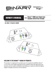
2.3 Rear Panel B-100-HDMATRIX-4X4
1
2
3
4
5
1. +5V DC interlocked power jack
2. RS-232 control port (DB9)
3. HDMI Inputs 1 through 4
4. HDMI Outputs 1 through 4
5. External IR Receiver (3.5mm Stereo)
2.4 Rear Panel B-100-HDMATRIX-8x8
2
1
5
6
3
1. +12V DC interlocked power jack
2. RS-232 control port (DB9)
3. HDMI Inputs 1 through 8
4. HDMI Outputs 1 through 8
5. External IR Receiver (3.5mm Stereo)
6. Ethernet Port
pg.6
4
B-100 HDMATRIX Installation and Users Manual 4X4 & 8X8
3. INSTALLATION
3.1 Installation Considerations
Binary HDMatrix switchers are designed with unsurpassed technology to provide superior
performance. However, where you install the switcher can have a large effect on the
performance that you receive, and the life of the unit. Here are some guidelines to follow
when installing a B-100- HDMatrix Switcher.
• Be sure that the unit is in a well-ventilated area that provides adequate cooling.
• Do not block the cooling vents located on both sides of the unit.
• Do not place the unit on carpeting or any similar material.
• Do not install the unit near a source of heat, or in an extremely humid or wet location.
• If your installation lacks good air flow (such as solid cabinet doors or wall-mounted
racks), it may be necessary to create ventilation to allow outside air into the space.
• Allow a minimum of 3” of free air space on either side of the unit. (Does not apply to
rack mounting)
• Allow a minimum of 2” of depth behind unit to accommodate cables and connectors.
• When placing on a cabinet shelf, position the unit with all feet resting on a
solid level surface.
3.1.1 Rack Installation
The B-100-HDMATRIX can be mounted in a rack with the front or rear panel facing outward.
This allows for easy access to the connections for installations that do not require the
front panel of the unit to be accessed. When mounting the rear panel facing out, it is
recommended that an IR receiver or Automation system is used.
© 2011 Binary
pg.7
B-100 HDMATRIX Installation and Users Manual 4X4 & 8X8
3.2 CONNECTIONS
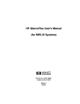
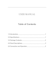
3.2.1 Basic Connections
Blu-ray/DVD
Player
IR Receiver
Cable/Sat
HD DVR
Game
Console
PC
HDMI Extender
Transmier
HDMI Extender
Receiver
Home Automaon
HDTV
HDTV
HD Projector
Examples
HDMI Sources
• Blu-ray /DVD Player
• Game Console
• Cable/Sat HD DVR
• PC
pg.8
Video Displays
• HD Flat-Panel
• HD Projector
• HD Flat Panel
• HDMI Extender
Control Devices
• IR Receiver
• Home Automation System
HDTV
B-100 HDMATRIX Installation and Users Manual 4X4 & 8X8
3.3 Control Ports
3.3.1 IR Receiver Connection
Pin out configurations for IR receivers and Automation Systems vary. Before connecting to
this input, review this section carefully in order to match the pin outs for the HDMatrix. Before
connecting an IR Receiver or to an IR Automation System, verify that the HDMatrix is OFF to
ensure proper operation when connected.
IR Signal
(Tip)
GND
(Ring)
12v DC
(Sleeve)
IR Signal
Tip
GND
Ring
12v DC
Sleeve
3.3.2 Connecting to an IR Automation System/Connecting block
When connecting to an IR Automation System or connecting block, the 12V DC (Sleeve)
must not be connected. Connections of this type require the use of the included Stereo
to Mono dongle or a custom cable made. A mono 3.5mm cable should not be used as it
will short out the 12 VDC to GND, and will make the connection inoperable.
3.3.2.1 Stereo to Mono IR Adaptor
To IR Control System/
Connecting Block
To B-100-HDMATRIX
12V DC (Sleeve)
GND (Ring)
IR Signal (Tip)
GND (Sleeve)
IR Signal (Tip)
3.3.2.2 Custom Cable Construction
To B-100-HDMATRIX
IR Signal (Tip)
GND (Ring)
12V DC (Sleeve)
GND (Ring)
IR Signal (Tip)
© 2011 Binary
12V DC (Sleeve)
(Tip)
To IR Control System/
Connecting Block
(Sleeve)
GND (Sleeve)
IR Signal (Tip)
pg.9
B-100 HDMATRIX Installation and Users Manual 4X4 & 8X8
3.3.3 RS-232 DB9 Serial Connection
The Binary™ HDMatrix receives control data on pin 2 (Rxd - Data Receive) and transmits
control data on pin 3 (TxD - Data Transmit). The connection cable between the HD MATRIX
and the Automation System will need to be configured so that pin2 (RxD) on the HD
MATRIX is connected to the Automation Systems Txd pin, and pin3 (TxD) on the HD MATRIX
is connected to the Automation Systems Rxd (Receive Data) pin. See below for details.
Configuration for the Automation System control ports can vary. Refer to the documentation
for the Automation System you are using to ensure proper connection and configuration.
This port is also used to communicate with a PC when using the PC Configuration Utility.
Refer to the Configuration Utility manual for details.
DB9 Female Connection
5
3 2
RxD (Data Receive)
TxD (Data Transmit)
GND
PIN
FUNCTION
2
RxD (Data Receive)
3
TxD (Data Transmit)
5
GND
In addition to the RS-232 DB9, the B-100-HDMATRIX-8x8 adds an Ethernet port that can be
used to control the device using Telnet Protocol. This port follows TIA 568 A/B standards;
refer to these when creating wiring.
pg.10
B-100 HDMATRIX Installation and Users Manual 4X4 & 8X8
4 EDID Configuration
While most HDMI sources can provide full HD, the displays used within an installation may not support
the features available from the source. In these cases, the display may not play the content being
provided by the source. It is necessary to make sure each source will provide a Video and Audio format
compatible with all displays that will view that source. This can be accomplished by managing the
EDIDs stored in the HDMatrix for each source. The stored EDID is per source, so all display locations will
see the same resolution and have the same audio format when that source is selected.
The following section explains configuring EDIDs via the IR Remote. Before configuring the EDID be
sure to refer to the source(s) and display(s) manuals for available features and resolutions for each
device.
While all EDID, configurations are available via the remote, a PC utility is also available on the HDMatrix
product pages, which can be found on the manufacturer’s website
(www.snapav.com).
When configuring EDIDs via IR, the ENTER key must be pressed within 10 seconds of the last command
in order to be processed.
Source Setup
Most sources have selections for Audio format and Video resolution that can fix the output so that it
will not change based on the EDID supplied by the connected display or switch. Check each source and
confirm that the audio format and video resolution are set so that they will change based on the EDID
negotiation. Normally this is a setting called “Auto” or similar.
Display Setup
It is recommended that the Consumer Electronics Control (CEC) is turned OFF in all displays when using
the HDMatrix. This will provide for proper communications of video/audio signals and allow EDIDs to
function at their optimum performance. Refer to the display’s manual for information on how to turn
this function OFF.
Verify that all displays are connected to the HDMatrix before continuing with EDID Configuration.
4.1 Basic EDID Configuration
The quickest and easiest method for configuration is to use Auto EDID. When used, the HDMatrix looks
at the EDID from each of the connected displays. It uses the lowest common denominator for video
resolution and audio format to create a new EDID , which is saved to all Inputs.
Note: Auto EDID sets audio to 2ch for all inputs regardless of the capability of the connected displays.
If multi-channel audio is desired, embedded EDIDs or Learned EDIDs will need to be used.
When to Use Auto EDID
• When all sources will be available on all displays.
• Every display in the system accepts the same video and audio resolution from the sources.
• As a first step to configuration following up with advanced methods for particular displays and
dedicated sources.
For advanced EDID configuration when using legacy display and/or dedicated sources, use embedded
EDIDs or learning as described in the following sections:
© 2011 Binary
pg.11
B-100 HDMATRIX Installation and Users Manual 4X4 & 8X8
Setting Auto EDID via IR Remote
Sets EDID Based on All Connected Displays
Display Readout (Example)
1. Press DEFAULT
2. Press Number Key 9
4. Press ENTER
EAA
A0
4.2 Advanced EDID Configuration
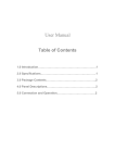
4.2.1 Embedded EDIDs Defaults
The B-100-HDMATRIX switchers contain 8 representative ‘embedded’ EDIDs that may be
assigned to Inputs. These EDIDs define groups of video and audio capabilities that are
useful for configuring sources in most systems.
When to Use Embedded EDIDs
• When audio and video characteristics of displays are known and compatible with the an Embedded EDID
Explanation of Embedded EDIDs
Video Resolution in the Embedded EDIDs is the highest resolution a connected source
will output; for example, if the source is capable of 1080P@60, it will be required by EDIDs
1-6 to provide that resolution. However, if the source is only capable of 1080i, it will output
1080i, etc. It is assumed that any display that can accept the specified Video Resolution can
also accept all standard video resolutions less than that specified.
Color Depth is the maximum number of bits used to encode color. 24bit color depth is
8bits per color (Red, Blue, Green) and 36bit color depth is 12 bits per color. When 36bit
color is used, the bandwidth increases substantially. This will dramatically reduce the
distance between the switch and the display when using an extender.
3D indicates that the source can output 3D if it is available in the content.
Audio Format indicates the maximum number of audio channels, as well as the audio
format that the source is allowed to output. For an Embedded EDID with 7.1ch Audio
Format, the source device will output the highest audio possible based on the content.
For example, if 7.1ch is not available and 5.1ch is, the output will be 5.1ch. The same holds
true if 2ch is the only audio available from the source.
Embedded EDIDs with 2Ch will limit output of the source to 2ch regardless of the formats
available in the content.
Embedded EDIDs 7 and 8 are provided for legacy displays that can only accept resolutions
up to a maximum of 1080i / 720p. The 1080i is listed first since almost all older HD displays
can accept 1080i, but not all can accept 720p. For these two Embedded EDIDs, (7&8) the
source will output 1080i. Should 1080i not be available, the source will output 720p. There
is a possibility that 720p may not work for a very small number of displays currently in use.
If you have such a display, you will need to use a Learned EDID (see below) from the display
to store in the Input EDID of any sources that will be routed to that display.
pg.12
B-100 HDMATRIX Installation and Users Manual 4X4 & 8X8
Embedded EDID Resolution
1
2
3
4
5
6
7
8
1080p@60Hz
1080p@60Hz
1080p@60Hz
1080p @60Hz
1080p@60Hz
1080p@60Hz
1080i@60Hz / 720p@60Hz
1080i@60Hz/ 720p@60Hz
Color Depth Audio
24-Bit
24-Bit
24-Bit 3D
24-Bit 3D
36-Bit 3D
36-Bit 3D
24-Bit
24-Bit
7.1ch
2ch
7.1ch
2ch
7.1ch
2ch
7.1ch
2ch
4.2.1.1 Setting EDID for Single Input
Example: Input =1 Embedded EDID=4
1. Press DEFAULT
2. Press Number Key (1-8) to select one Embedded
EDID
Display Readout (Example)
E4A
3. Press INPUT
4A
4. Press Number Key (1-8) to select the Input to
which the EDID is applied
41
5. Press ENTER
-FF
(success)
(fail)
4.2.1.2 Setting EDID for All Inputs
Example: Input=All Embedded EDID=4
1. Press DEFAULT
2. Press ALL to select all Inputs
3. Press Number Key (1-8) to select Embedded EDID
4. Press ENTER
© 2011 Binary
Display Readout (Example)
EE4A
-FF
(success)
(fail)
pg.13
B-100 HDMATRIX Installation and Users Manual 4X4 & 8X8
4.2.2 Learning EDID
For more advanced EDID configuration, learning can be used to assign EDIDs. When used
,the EDID from a particular display is assigned to a particular source or all sources. This
is useful when the system contains a display that may not output the highest resolution
available from the sources.
When to Use Learned EDIDs
• An older display does not work properly with any of the embedded EDIDS.
• When the source is a PC, it may be necessary to use a learned EDID.
• Learning EDID to a Single Input.
Example: Input =1 EDID Learned from Output 4
1. Press LEARN
2. Press OUTPUT
3. Press Number key (1-8) to select the Output the
EDID is learned from
4. Press INPUT
5. Press Number Key (1-8) to select the Input to
which the EDID is applied
6. Press ENTER
Display Readout (Example)
L.-.
1A
14
L1A
-FF
(success)
(fail)
4.2.2.1 Learning EDID to All Inputs
Note that learning the EDID for a display to all sources is the same as using Auto EDID.
Example: Input=All EDID Learned from Output 4
1. Press LEARN
Display Readout (Example)
L.-.
2. Press OUTPUT
3. Press Number Key (1-8) to select the Output the
EDID is learned from
4. Press ENTER
pg.14
4
-FF
(success)
(fail)
B-100 HDMATRIX Installation and Users Manual 4X4 & 8X8
4.3 EDID Status
Once EDIDs are configured, the assigned EDID for sources can be reviewed to ensure that
the desired output is configured or for troubleshooting.
Example: Input=3
Display Readout (Example)
EDID 5 Assigned
from Embedded
EDID Table
EDID Learned
from Output 4
3. Press Number Key (1-8)to select the desired Input
---3
---3
4. Press ENTER
5.3.
4.3
1. Press STATUS
2. Press INPUT
• If the second digit (the Input being queried) has a dot after it, then the first digit is
the EDID number from the Embedded EDID table.
• If the second digit (the Input being queried) does not have a dot after it, then the
first digit is the Output the EDID was learned from.
5 Advanced Configuration
During the installation of an HDMatrix, there are settings that provide Advanced Configuration above
the use of the remote. These allow for fine tuning the HDMatrix when used under certain conditions
and the settings listed below are not available from the remote.
For more information refer to the Configuration Utility manual available on the SnapAV website
5.1
PC Configuration Other Settings
The following settings can be found in the PC Configuration Utility Other Settings menu.
5.1.1 IR Receiver Active
Use this setting to disable the front panel IR receiver to avoid IR command conflicts and prevent IR
flooding of the HDMatrix. When IR is disabled, RS232 or IP must be used to control the HDMatrix.
5.1.2 Front Panel Power Button Active
Use this feature to disable/Enable the front panel power button of the HDMatrix when using an
Automation System. This will prevent the HDMatrix from being powered OFF and preventing control
of the device from an automation system UI.
5.1.3 HDMI Input EQ Setting
Use these settings when an HDMI image contains video noise and artifacts that can occur during
switching or viewing some HDMI sources or displays. Each input can be set to High when video noise
is present. We recommend that this be set to LOW as a starting point, and only changed should video
noise be present on a particular input.
© 2011 Binary
pg.15
B-100 HDMATRIX Installation and Users Manual 4X4 & 8X8
6 OPERATION AND CONTROL
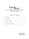
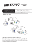
6.1 IR Remote
Key
Function
1
ON
Power on the matrix switcher
2
OFF
Enter standby mode
3
Number Keys 1-9
Select a number
4
10+
Not Used
5
All
Select all Inputs or Outputs
6
Enter*
Enter to trigger the previous setting
7
OUTPUT
Begin output selection
8
INPUT
Begin input selection
9
OUTPUT OFF
Turn off/Mute the selected Output
10
STATUS
Present EDID or Output status
11
LEARN
Learn EDID from one output
12
DEFAULT
Begin Embedded EDID Selection
13
CLEAR
Clear the former IR operation procedure which user just
pressed but has not yet applied by pressing ENTER
POWER
ON
2
1
3
2
4
5
7
8
ALL
5
STATUS
10
10+
4
5. Press ENTER
34
Input to All Outputs
Example: Output=All Input=4
1. Press OUTPUT
2. Press ALL to select all Outputs
3. Press INPUT
4. Press Number Key (1-8) to select Input
6. Press ENTER
pg.16
INPUT
9
OUTPUT
LEARN
11
Display Readout (Example)
-AAA4
44
ENTER
OFF
6
Display Readout (Example)
4.Press Number Key (1-8) to select Input
3. Press INPUT
6
9
-3334
2. Press Number Key (1-8) to select Output
OUTPUT
8
6.1.1 Route Inputs to Outputs
1. Press OUTPUT
3
7
*The ENTER key must be pressed within 10 seconds of the last command in order to be processed.
Input to Single Output
Example: Output=3 Input=4
OFF
1
DEFAULT
CLEAR
12
13
B-100 HDMATRIX Installation and Users Manual 4X4 & 8X8
6.1.2 Turn Off (Mute) Outputs
Mute one Output Example: Output=1
Display Readout (Example)
-110
10
1. Press OUTPUT
2. Press Number Key (1-8) to select Output
3. Press OUTPUT OFF
4. Press ENTER
Mute All Outputs
Display Readout (Example)
1. Press OUTPUT
-AA0
40
2. Press ALL to select All Outputs
3. Press OUTPUT OFF
4. Press ENTER
6.1.3 Display Status
Example: Input=3
Display Readout (Example)
Example Output=3, Input=4
Example Output=3 Muted
3. Press Number Key (1-8) to select one Output
--3-
--3-
4. Press ENTER
34
30
1. Press STATUS
2. Press OUTPUT
6.1.4 Resetting to Factory Defaults
This procedure resets the B-100-HDMATRIX to factory defaults:
EDIDs - 1080i Stereo (embedded 8), I/O - All Outputs set to Input 1, DHCP (8x8 only) - Enabled.
Display Readout
(Example)
1. Press DEFAULT
2. Press DEFAULT
3. Press DEFAULT
4. Press DEFAULT
5. Press ENTER
E--DD
D-
Note that resetting factory defaults can take up to 2 minutes to complete.
© 2011 Binary
pg.17
B -1 0 0 H D MAT R I X I ns ta lla tion a nd U s e r s Ma nua l 4 X 4 & 8 X 8
7. SPECIFICATIONS
B-100-HDMATRIX-4x4
B-100-HDMATRIX-8x8
Technical
Product Type
True 4x4 HDMI matrix
True 8x8 HDMI matrix
HDMI compliance
Full HD 1080P60, Deep Color (36bit),
3D (1.4a 3D)
Full HD 1080P60, Deep Color
(36bit), 3D (1.4a 3D)
HDCP compliance
Version 2.0
Version 2.0
Video bandwidth
Single-link 225MHz [6.75Gbps total
bandwidth]
Single-link 225MHz [6.75Gbps total
bandwidth]
Video support
1080p / 1080i / 720p /480p / 480i
up to 36-bit color
1080p / 1080i / 720p /480p / 480i
up to 36-bit color
Dolby TrueHD
Dolby Digital Plus
DTS-HD Master
DTS-HD
LPCM
Dolby Digital EX
DTS-ES
Dolby Digital
DTS
Dolby TrueHD
Dolby Digital Plus
DTS-HD Master
DTS-HD
LPCM
Dolby Digital EX
DTS-ES
Dolby Digital
DTS
2ch:
PCM
2ch:
PCM
ESD: IEC 61000-4-2 Level 4 (15KV)
Surge: IEC 61000-4-5
ESD: IEC 61000-4-2 Level 4 (15KV)
Surge: IEC 61000-4-5
Input
4x HDMI
1x RS-232
1x System IR (3.5mm jack)
8x HDMI
1x RS-232
1x System IR (3.5mm jack)
1x Ethernet Port
Output
4x HDMI
8x HDMI
IR remote or RS-232
IR remote, RS-232 or Ethernet
HDMI connector
Type A [19-pin female]
Type A [19-pin female]
RS-232 connector
9-pin DB9 female
9-pin DB9 female
Ethernet Connector
N/A
RJ45
Audio support
IR remote control
Mechanical
HousingV
Dimensions
(W x H x D)
Weight
Power supply
Storage temperature
pg.18
Metal enclosure
Metal enclosure
Switcher
17.31” x 1.75” x 5.25”
17.31” x 1.75” x 6.5”
Package
21” x 3.1” x 10.4”
21” x 3.1” x 10.4”
4.4 lbs
5.4 lbs
1RU rack-mount. Ears included
1RU rack-mount. Ears included
5V 4A DC
12V 5A DC
32~104°F]
32~104°F]
-20~60°C -4~140°F
-20~60°C -4~140°F
B-100 HDMATRIX Installation and Users Manual 4X4 & 8X8
8. WARRANTY
Two-Year Limited Warranty
This Binary™ product has a 2-year limited Warranty. This warranty includes parts and labor
repairs on all components found to be defective in material or workmanship under normal
conditions of use. This warranty shall not apply to products which have been abused,
modified or disassembled. Products to be repaired under this warranty must be returned
to SnapAV® or a designated service center with prior notification and an assigned return
authorization number (RA).
© 2011 Binary
pg.19
© 2011 Binary
140407-1100