Download SPEKOL 2000 UV VIS Spectrophotometer
Transcript
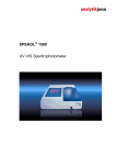
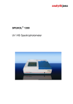
SPEKOL® 2000
UV VIS Spectrophotometer
Analytik Jena AG
Kundendienst
Konrad-Zuse-Str. 1
07745 Jena
Phone:
e-mail:
Hotline:
+ 49 (3641) 77-7407
Fax:
+ 49 (3641) 77-7449
[email protected]
General information about Analytik Jena AG
on the internet: http://www.analytik-jena.de
Copyrights and Trademarks
Microsoft, Windows are registered trademarks of Microsoft Corp.
Publication No.: 210:021.23
Edition – January 2008
Technical documentation made by:
Analytik Jena AG
This documentation describes the state of this product at the time of publishing. It
need not necessarily agree with future versions of the product.
Subject to change!
© Copyright 2008 Analytik Jena AG
Contents
Contents
®
Manual SPEKOL 2000
Analytik Jena AG
1
Introduction .....................................................................3
1.1
Intended use of SPEKOL 2000 .............................................................3
1.2
SPEKOL 2000 warning labels...............................................................3
1.3
Practical notes for working with this Manual .........................................4
2
Safety notes .....................................................................5
3
Technical data .................................................................7
4
Connectors and display elements .................................9
5
Installation and start-up................................................11
5.1
Installation conditions..........................................................................11
5.2
Connecting the SPEKOL 2000............................................................12
6
Care, maintenance & replacement of lamps ...............13
6.1
Care and maintenance........................................................................13
6.2
Cleaning ..............................................................................................13
6.3
Replacement of fuses .........................................................................13
6.4
Replacement of lamps ........................................................................14
7
Measurement parameters for spectrophotometers of
SPEKOL series ..............................................................17
7.1
Measurement parameters window for scanning spectrophotometers 17
7.2
SPEKOL: Settings tab.........................................................................19
7.3
SPEKOL: Device tab...........................................................................21
7.4
SPEKOL: Mode tab.............................................................................21
7.4.1
Measuring mode: Scan Mode .............................................................22
7.4.2
Measuring mode: Time Scan ..............................................................22
7.4.3
Measuring mode: Wavelengths...........................................................24
8
First measurement with SPEKOL ................................25
9
Disposal .........................................................................27
10
Table of figures..............................................................29
Issue 01/2008
1
Contents
2
Issue 01/2008
®
Manual SPEKOL 2000
Analytik Jena AG
Introduction
Intended use of SPEKOL 2000
1
Introduction
1.1
Intended use of SPEKOL 2000
The SPEKOL® 2000 is a compact, computer-controlled two-beam spectral photometer to
measure the transmission, extinction, concentration and energy level of liquid samples. It
is designed to perform measurement within the spectral range of 190 nm to 1100 nm. Its
optical system ensures genuine real-time operation, so even variations in the absorption
of a reference sample can be compensated while measurement is going on. Combined
with powerful WinASPECT® software, the SPEKOL® 2000 is particularly suited for
applications in clinical, biochemical, chemical or environmental laboratories, as well as
other sectors of routine analytics, research, development and quality control.
This User Manual contains a detailed description of the SPEKOL® 2000, its
specifications, available accessory items and useful advice on maintenance.
Once the photometer has been carefully unpacked, you should visually check for
completeness of delivery against the packing list. Likewise, one should perform an
inspection for proper condition. On noticing any kind of non-conformity, you are advised
to immediately contact our Representative Office or our Service.
1.2
SPEKOL 2000 warning labels
Warning notes at the SPEKOL® 2000 must be followed!
The following warning labels are provided at the SPEKOL® 2000:
Disconnect power cable!
Always remember to disconnect the power plug before you open the product casing or
replace a fuse!
Danger! UV radiation!
Do not look into the radiation that is emitted by the UV lamp, whether directly or
indirectly using a mirror. Exposure to lamp radiation may cause conjunctivitis!
Danger! Hot surface!
Once a lamp is turned on, its shield will heat up strongly. To replace a lamp or remove
its shield, turn the lamp off and allow for sufficient time to cool down.
®
Manual SPEKOL 2000
Analytik Jena AG
Issue 01/2008
3
Introduction
Practical notes for working with this Manual
1.3
Practical notes for working with this Manual
Throughout this Manual, special warning and information symbols are used:
Warning!
Warning messages alert you to a specific procedure or practice, which, if not followed
correctly, may cause personal injury.
Caution!
Caution messages refer you to procedures which, if not observed, may result in
damage to the equipment.
Dangerous electric voltage!
Emission of UV radiation!
Disconnect power cable!
Note
This note must be followed to obtain correct measurement results.
For easier navigation, this Manual is organized as follows:
4
•
Chapters and illustrations are numbered consecutively.
•
Every illustration has its own caption.
•
Working steps are numbered.
•
Cross-references to other sections are marked by an arrow (e.g. → Practical
Notes for Working with this Manual p. 4)
Issue 01/2008
®
Manual SPEKOL 2000
Analytik Jena AG
Safety notes
2
Safety notes
For your personal safety and for a trouble-free operation, carefully read this chapter
before starting up the SPEKOL® 2000.
Observe all safety notes given in this Manual and all messages and control software
notes displayed on the screen.
In addition, observe the safety notes for system components of other manufacturers (e.g.
PC, printer) supplied together with the device.
In particular, you should also observe the safety notes given on the labels and the
information on the use, storage and disposal of reagents, reaction cells and the notes on
the package inserts of test kits.
Intended use!
The SPEKOL® 2000, including any original accessory, may only be used for the
applications described in this Manual. The manufacturer cannot assume liability for any
other application, including that of individual modules or single parts. This also applies to
all service or repair work that is not carried out by authorized service personnel. All
warranty claims shall be forfeited.
Local safety regulations!
Observe local safety regulations that are relevant to SPEKOL® 2000 operation (e.g.
labor-safety regulations, regulations for prevention of and protection against accidents).
References to potential risks given in this manual do not replace the relevant laborsafety regulations that are to be followed.
Personnel!
The SPEKOL® 2000 may only be operated by appropriately qualified and trained
personnel.
For this reason, knowledge of the information provided by this Manual is indispensable.
and assumed to have been obtained.
Emergency stop!
In the case of an emergency, disconnect the SPEKOL® 2000 and its components from
line power supply by removing the power plug from the power outlet.
Electric shock!
The SPEKOL® 2000 is electrically powered. At several parts inside the system,
extremely hazardous electrical voltages are accessible!
To ensure Protection Class I (protective earth connection) of the device, connect the
power plug of the device only to a power outlet with protective earth conductor. The
protective effect must not be undone by the use of an extension cable without protective
earth conductor.
Before opening the device or removing any device covers, disconnect the power cable!
Before connecting the SPEKOL® 2000 to the power outlet, make sure the line voltage
supplied agrees with the operating voltage specified on the rating plate at the rear panel
of the device. Operation of the device with any other operating voltage than that
specified may result in the destruction of the device.
Only use fuses of the specified type.
®
Manual SPEKOL 2000
Analytik Jena AG
Issue 01/2008
5
Safety notes
Do not operate the SPEKOL® 2000 in rooms with an explosive
atmosphere!
UV radiation!
Never look into a lamp beam, whether directly or indirectly, e.g. via a mirror. Failure to
comply may cause conjunctivitis!
Turn power off for lamp replacement!
Hot surface!
The lamphouse will heat up strongly while the lamps are on. Physical contact with the
hot lamp house surface may cause skin burns.
Turn the SPEKOL®2000 off before you proceed to lamp replacement, detach the power
plug and wait until the lamps have cooled down sufficiently.
Lamp damage!
Do not hold a halogen or deuterium lamp in normal working state by its glass bulb.
Contamination on the bulb affects the radiation properties of the lamps.
Especially protect the beam-exit window of the deuterium lamp.
Make sure to remove the protective cap from the halogen bulb after having inserted it to
avoid any risk of fire!
Non-observance will result in damage of the lamp.
Heat build-up
Heat accumulation might result in overheating and operating faults.
®
Make sure not to cover up the ventilation slots of the SPEKOL 2000!
®
Before you switch on the SPEKOL 2000, remove its dust cover!
Handling of liquids
Take care to ensure that no liquids can enter the SPEKOL® 2000 to avoid any damage
to the device.
Risk of corrosion
Do not set up the device in the vicinity of aggressive vapors, e.g. strongly corrosive acid
or caustic vapors! The vapors might corrode the connections, mechanical and optical
components of the device.
Avoid exposing the sample compartment to strongly corrosive substances! For the
analysis of such samples, use vapor-tight stoppered cells.
After the measurement, do not leave the samples unnecessarily long in the sample
compartment of the device!
6
Issue 01/2008
®
Manual SPEKOL 2000
Analytik Jena AG
Technical data
3
Technical data
SPEKOL® 2000
Technical data
®
Manual SPEKOL 2000
Analytik Jena AG
Optical system
Double-beam spectrophotometer, PC controlled
Optical slit width
0.5, 1, 2, and 4 nm
Wavelength range
190-1100nm
Wavelength accuracy
≤ ± 1 nm
Photometric range
-0.1A to 3A,
Photometric accuracy
≤ ± 0.01 A at 1 A
Long-term stability at 500 nm
≤ ± 0.004 A/h
Toluene / hexan resolution
> 1.6
Line voltage
230 VAC or 115 VAC (switchable)
Line frequency
50 ... 60 Hz
Fuses:
Line fuses
2x T 4 AH
Temperature range
+15°C … +35°C
Humidity
< 85%
Weight
22 kg
Dimensions (W x H x D)
410 x 275 x 656 mm3
Power consumption
200 VA
Issue 01/2008
7
Technical data
8
Issue 01/2008
®
Manual SPEKOL 2000
Analytik Jena AG
Connectors and display elements
4
Connectors and display elements
1
Lid of sample compartment
2
Lid for extended sample compartment
3
Status indicator LEDs
Fig. 1
SPEKOL® 2000 overall view
1
Fig. 2
®
Manual SPEKOL 2000
Analytik Jena AG
RS 232 port (PC)
SPEKOL® 2000 PC terminals on left-hand side panel
Issue 01/2008
9
Connectors and display elements
1
Ventilation slots
Nameplate
3
Line power inlet jack
Fan
Fig. 3
SPEKOL® 2000 rear-side terminals
1
Selector switch to convert to 110
V or 220 V supply level
Fig. 4
2
Fuse holder
3
Line power switch
®
SPEKOL 2000 right-hand panel terminals
Sample compartment
Fig. 5
1
Cell holder (reference)
2
Cell holder (sample)
SPEKOL® 2000 sample compartment
Both the measuring beam and the reference beam enter the sample compartment from
the back. Two windows are provided to protect the photometer space from dust and
exposure to reagents.
The holder pocket for the measuring cell (2) is located in front-left position and that for
the reference cell in back-right position (1).
10
Issue 01/2008
®
Manual SPEKOL 2000
Analytik Jena AG
Installation and start-up
Installation conditions
5
Installation and start-up
5.1
Installation conditions
Caution!
Do not cover any of the ventilation slots!
Do not place any objects on the SPEKOL® 2000!
Do not operate the SPEKOL® 2000 in rooms where there is risk of an explosion!
Keep aggressive vapors, e.g. strongly corrosive acid or caustic vapors away.
The installation site of the SPEKOL® 2000 must meet the following requirements:
•
The place should be free of draft, dust, corrosive vapors as well as vibrations.
•
Do not set up the SPEKOL® 2000 near electromagnetic fields (e.g. of motors).
•
Avoid dripping or splashing water near the instrument.
•
Do not expose the device to direct sunlight or the radiation of heaters.
•
Temperature range:
+ 15 ... + 35 °C
•
Humidity:
up to 85% (at + 30 °C)
Footprint requirements
Based on its specified overall dimensions plus an extra 100 mm stripe of clearance on
all sides, the SPEKOL® 2000 requires a minimum footprint area of 610 x 765 mm2.
®
Manual SPEKOL 2000
Analytik Jena AG
Issue 01/2008
11
Installation and start-up
Connecting the SPEKOL 2000
5.2
Connecting the SPEKOL 2000
Observe correct position of device!
Move the SPECORD® only in upright position (observe label on transport case).
Do not turn the device upside down.
Electric shock
Check that the nameplate specification for operating voltage is in agreement with the
actual level of line voltage supply before you connect the SPEKOL® 2000 to a mains
supply point. Operation at any other than the specified voltage level may result in
®
destruction of the SPEKOL 2000.
Make absolutely certain that the voltage selector switch (Fig. 4 p.10) is set to the right
mains voltage level.
1.
Carefully unpack shipping case contents and visually check product delivery.
2.
Remove all air stream obstacles below and around the product.
3.
Set the selector switch to the right voltage level (1 in Fig. 4 p.10).
4.
Connect line power cable to power inlet (Fig. 4 p.10), then plug power connector
into power socket.
5.
Use RS232 cable to connect the SPEKOL® 2000 (Fig. 2 p.9) and the PC to a free
COM port.
6.
Remove cells or other obstacles (as may be necessary) from the light beam path in
the sample compartment.
7.
Use main power switch to turn power on (3 in Fig. 4 p.10).
8.
Start your PC and install WinASPECT software if necessary, using the special
SPEKOL® 2000 driver (refer to WinASPECT manual).
9.
Launch WinASPECT software and select SPEKOL® 2000 via Measurement /
Configuration Measurement.
10. Select Set parameters in Measurement. Then check “Device“ tab for correct COM
interface setting.
11. Trigger initialization routine via Measurement / Full Initialization. This function test
may take some minutes to run through. Keep the sample compartment closed until
initialization is complete.
Allow for run-in time of 20 minutes!
Wait for the SPEKOL® 2000 to reach a thermally stable condition (approximately 20
minutes) before you trigger the first measurement job.
Caution!
During measurement, the sample compartment cover must be closed!
The SPEKOL® 2000 is ready for operation.
12
Issue 01/2008
®
Manual SPEKOL 2000
Analytik Jena AG
Care, maintenance & replacement of lamps
Care and maintenance
6
Care, maintenance & replacement of lamps
6.1
Care and maintenance
The SPEKOL® 2000 is largely free of maintenance.
To ensure your laboratory certification with device validation, Analytik Jena AG offers
you a service/maintenance agreement.
User care and maintenance is limited to the following operations:
•
Cleaning of sample compartment and product casing
•
Lamp replacement
•
Replacement of line fuses
You should only use spares from Analytik Jena AG.
You can order consumables and wear parts by phone from our Service Department.
In the case of malfunction of the device, please contact our Service Department. For the
address, refer to the → inside cover page.
6.2
Cleaning
Avoid keeping filled cells unnecessarily long in the sample compartment to prevent the
spectrometer from being affected by any solvent vapors.
Wipe off spilt samples in the sample compartment or on accessory units instantly with
cleaning tissue.
Wipe off contamination on the instrument with a soft, clean cloth slightly moistened with
a commercially available, neutral detergent.
6.3
Replacement of fuses
A defective line fuse can be replaced.
Danger! Electric shock!
Use main power switch to turn electric supply to the SPEKOL® 2000 off and detach line
power cable from power inlet of the SPEKOL 2000 before you replace a fuse.
1.
Disconnect line power cable from SPEKOL® 2000.
2.
Open fuse holder (→ Fig. 4 p.10) by turning the bayonett connector to the left. Use
a screwdriver for this purpose.
The fuse holder will slightly come up, once it is disengaged.
3.
Take fuse holder with fuse out and replace fuse.
For replacement, use only fuses of this type:
•
4.
®
Manual SPEKOL 2000
Analytik Jena AG
T 4 AH
Put fuse holder back into place and lock bayonet connector.
Issue 01/2008
13
Care, maintenance & replacement of lamps
Replacement of lamps
5.
6.4
Reconnect line power cable to the SPEKOL® 2000 on one end and to the line
power socket on the other end.
Replacement of lamps
Danger! Electric shock!
Use main power switch to turn electric supply to the SPEKOL® 2000 off before you
replace a halogen lamp!
Danger! Hot lamps!
The lamps heat up strongly during operation. Allow for sufficient cooling down before
you replace a lamp.
Danger! Eye injury from exposure to optical radiation!
Do not look into a burning lamp! Its radiation may damage your eyes.
Soiling of lamps!
Do not touch the glass body of a new lamp. Use particular care to protect the beam
outlet window (of quartz glass) of the deuterium lamp!
If there was finger contact with a glass body, use a piece of clean non-shedding cloth
and pure alcohol to wipe any finger marks off. Contamination will deteriorate the lamp’s
performance features.
Open lamphouse
1.
Turn the SPEKOL® 2000 off and detach its power plug.
2.
Remove all samples, cells and unfixed parts from the sample compartment.
3.
Place the SPEKOL® 2000 onto a soft support base, turning it upside down in order
to provide access to the bottom side.
Fig. 6
4.
14
1
Screws
2
Lamp cover
Lamphouse cover at the bottom of the SPEKOL® 2000
Turn out both screws (1) and remove lamphouse cover (2) on the bottom side.
Issue 01/2008
®
Manual SPEKOL 2000
Analytik Jena AG
Care, maintenance & replacement of lamps
Replacement of lamps
1
Fixing screws of deuterium lamp
2
Deuterium lamp with lamp base
3
Fixing screw for halogen lamp holder
4
Connector for deuterium lamp
5
Knurled thumb screws to fix feed wires of halogen lamp
Fig. 7
SPEKOL® 2000 lamphouse with cover removed
Replacement of halogen lamp
®
Manual SPEKOL 2000
Analytik Jena AG
1.
Open lamphouse (as described above).
2.
Loosen knurled thumb screws for fixing of halogen lamp feed wires (5 in Fig. 7) and
remove cables from their clamping points.
3.
Unscrew fixing screw (3 in Fig. 7) of halogen lamp holder, then cautiously retrieve
the holder from the inner space.
Issue 01/2008
15
Care, maintenance & replacement of lamps
Replacement of lamps
Fig. 8
1
Halogen lamp
2
Bracket with springs
3
Holder
Holder base of halogen lamp
4.
Pull bracket (3 in Fig. 8) from halogen lamp. Remove halogen lamp from its holder
base (1 in Fig. 8).
5.
Cautiously insert the new halogen lamp into the holder base. Prevent hand contact
with the lamp’s surface. Use a non-shedding cloth and alcohol to wipe off
contamination or dirt. Install spring back onto the halogen lamp.
6.
Put holder base with the new halogen lamp back into place. Fix it with the screw (3
in Fig. 7).
7.
Clamp cable ends again with the help of knurled thumb screws (5 in Fig. 7).
8.
Close lamphouse cover (2 in Fig. 6) and fix cover with the two screws (1 in Fig. 6).
9.
Cautiously turn the SPEKOL® 2000 around again.
Replacement of deuterium lamp
1.
Open lamphouse (as described above).
2.
Unfix connector of deuterium lamp (4 in Fig. 7).
3.
Unscrew fixing screw for deuterium lamp holder base (1 in Fig. 7) and cautiously
remove lamp from the inner space.
Caution!
Do not touch the deuterium lamp with bare fingers. Use a piece of paper or nonshedding cloth for replacement to prevent soiling of lamp surfaces.
16
4.
Install the new deuterium lamp and fix it with the two screws (1 in Fig. 7).
5.
Fix connector (4 in Fig. 7).
6.
Close lamphouse cover (2 in Fig. 6) and fix cover with both screws (1 in Fig. 6).
7.
Turn the SPEKOL® 2000 cautiously around into working position.
Issue 01/2008
®
Manual SPEKOL 2000
Analytik Jena AG
Measurement parameters for spectrophotometers of SPEKOL series
Measurement parameters window for scanning spectrophotometers
7
Measurement parameters for spectrophotometers of SPEKOL
series
This Manual only contains measurement and performance settings that are valid for
SPEKOL series products. For a description of any other WinASPECT® software function
that facilitates data evaluation and data handling, you should refer to the "WinASPECT®
- Software for Spectrophotometers" manual.
7.1
Measurement parameters window for scanning
spectrophotometers
In the measurement parameters window, choose the settings required for the
measurement. You can save the settings to a parameter file. This allows you to create
parameter files for different analytical tasks and recall them at any time for a
measurement.
Open the measurement parameters dialog box by activating menu command
Measurement / Set Parameters.
Fig.7-1
Device driver dialog box
The dialog box contains a toolbar with labeled buttons as well as four tabs (Settings,
Device, Mode) for the selection of measurement parameters.
®
Manual SPEKOL 2000
Analytik Jena AG
Issue 01/2008
17
Measurement parameters for spectrophotometers of SPEKOL series
Measurement parameters window for scanning spectrophotometers
Toolbar functions
Function
Description
Confirms the selected parameters for the following measurement(s) and
closes the device driver dialog box.
The measurement parameters thus become the "current" measurement
parameters.
Rejects any previous changes of measurement parameters and closes the
device driver dialog box. The changes will not be activated for the
following measurement(s).
Opens a saved measurement parameter file.
The Open standard dialog box appears.
The default path for measurement parameter files is *\WinASPECT\para\
Saves the current settings of measurement parameters to the currently
active file.
Saves the current settings of measurements parameters to a new file.
This will bring up the Windows standard dialog box for saving files, where
you can choose a new name.
Opens the Online Help on measurement parameter settings.
18
Page
Layout
Opens the dialog box for setting the page layout(→ Section "Printing files"
®
in WinASPECT manual).
Printer
Setup
Opens the dialog box for selecting printer-specific options.
Preview
Opens a dialog box with a preview of the printout.
Print
Starts the printout of measurement parameters.
Issue 01/2008
®
Manual SPEKOL 2000
Analytik Jena AG
Measurement parameters for spectrophotometers of SPEKOL series
SPEKOL: Settings tab
7.2
SPEKOL: Settings tab
®
Fig.7-2 Measurement parameters – Scanning SPEKOL Settings tab
Title
Entries in this textbox are optional.
In this textbox, enter e.g. a designation for the type of measurement to be taken with this
parameter file.
Cycle Mode
Here, choose single or cyclic repeat measurements.
The results of cyclic repeat measurements are stored together in cycle files.
Option
Description
None
Runs a single measurement (normal measuring mode).
Manual
Runs repeat measurements of a sample.
The individual sample measurements are started "manually". After
every measurement, a dialog box appears allowing you to start
another sample measurement or terminate the measurement
series.
In this mode, you need not define in advance the number of
measurements to be taken in the cycle.
Automatic
Runs automatic repeat measurements of a sample.
In the Number textbox, type the number of repeat measurements
to be run.
Time controlled
Time controlled repeat measurements for reaction kinetics.
In the Number textbox, type the number of repeat measurements
to be run.
In the Interval time textbox, enter the desired time interval
between successive measurement starts within a measurement
series in seconds.
®
Manual SPEKOL 2000
Analytik Jena AG
Issue 01/2008
19
Measurement parameters for spectrophotometers of SPEKOL series
SPEKOL: Settings tab
Consider that for the actual measurement a certain time is needed.
If the interval time turns out to be too short during the
measurement, the program switches over to the Automatic mode
and the measurement will then be executed as fast as possible.
Note
The time controlled cycle mode is suitable for kinetic measurements over a spectral
range or at several discrete wavelengths. For time-dependent measurements at a single
wavelength only, the Time Scan mode selectable on the Mode tab is more comfortable
and better suitable (→Section "Measuring mode: Time Scan" p. 22).
Display
In this field, select the desired ordinate unit and the ordinate range in which the results
shall be displayed while the measurement is running.
Choose the desired option:
•
Transmission
•
Absorbance
•
Energy
In the Min and Max textboxes, enter the desired lower and upper limits of the display
range.
Correction
In this field, you can choose the type of baseline correction (reference measurement):
Option
Description
No
No baseline correction is carried out.
Reference
A reference is measured before the sample.
This registration of reference data is performed using the same
measurement parameters as in the following sample measurement.
In most cases, distilled water or the solvent of the sample is used
as reference.
20
Issue 01/2008
®
Manual SPEKOL 2000
Analytik Jena AG
Measurement parameters for spectrophotometers of SPEKOL series
SPEKOL: Device tab
7.3
SPEKOL: Device tab
On this tab, choose slit width (spectral resolution), the interface for PC connection and
the lamp-change wavelength.
®
Fig.7-3
Measurement parameters – Scanning SPEKOL - Device tab
COM Port
From this list box, choose the COM port of the PC to which the SPEKOL® has been
connected.
Slit (adjustable only for SPEKOL® 2000)
Choose the spectral slit width (optical resolution) to be used for the measurement:
®
SPEKOL 2000
SPEKOL® 1500
SPEKOL® 1300
0,5, 1; 2; 4 nm
4 nm
4 nm
Lamp change (not available for SPEKOL® 1300)
From this list box, select the lamp to be used for sample measurement or the
wavelength, at which the lamp shall be changed.
7.4
SPEKOL: Mode tab
On this tab, choose the desired measuring mode. The Meas. mode list box provides the
following options:
•
Scan Mode
•
Time Scan
•
Wavelengths
Depending on the selected measurement mode the appearance of the bottom part of the
Mode tab changes and shows only those options (textboxes, list boxes and buttons) that
are necessary for this mode.
®
Manual SPEKOL 2000
Analytik Jena AG
Issue 01/2008
21
Measurement parameters for spectrophotometers of SPEKOL series
SPEKOL: Mode tab
7.4.1
Measuring mode: Scan Mode
In Scan Mode, the grating drive is continuously moving on during the measurement.
Fig.7-4
Mode tab - Activated Scan Mode
Parameter
Description
Range [nm]
Wavelength range of the scan.
Setting range:
190 nm ... 1100 nm
Delta lambda [nm] Data point interval (step size) in the selected spectral range.
Setting range:
7.4.2
0.1 ... 10 nm
Measuring mode: Time Scan
In this mode, you may measure a sample repeatedly at a fixed, preselected wavelength.
Fig.7-5
22
Mode tab – Activated Time Scan
Parameter
Description
Wavelength [nm]
Wavelength to be used.
Issue 01/2008
®
Manual SPEKOL 2000
Analytik Jena AG
Measurement parameters for spectrophotometers of SPEKOL series
SPEKOL: Mode tab
Setting range
190 nm ... 1100 nm
Wait time [s]
The wait time is the delay between the release of the measurement
and the first actual measurement.
This time can be used as reaction time after the addition of the
starting reagent for a kinetic measurement.
Measuring time
The total measuring time can be subdivided into maximally four
partial periods. For every partial period, you can define the
measuring times and the integration times individually.
The measuring time is the time used for one partial period. It can
be specified in seconds or minutes (to be selected from the
corresponding list box).
Data points [s]
List boxes for selection of temporal "data point interval". This
parameter indicates the time after which the next measurement is
started.
Setting range: 1 ...50,0 s
You can also left-click on the boxes and enter any desired time via
the keyboard.
In kinetic measurements, after activation of menu command Measurement /
Measurement or a click on
, first the system will make the necessary device
settings (driving to measurement wavelength, checking the reference, etc.). The actual
measurement or wait time (see above) begins only after you confirmed the program
query "Start time cycle? [OK]". Thus, there is sufficient time left for preparing the
sample, such as the addition of a starting reagent.
Note
When you select the Time Scan mode, a cycle mode (automatic, time controlled)
previously selected on the Settings tab will be deactivated.
®
Manual SPEKOL 2000
Analytik Jena AG
Issue 01/2008
23
Measurement parameters for spectrophotometers of SPEKOL series
SPEKOL: Mode tab
7.4.3
Measuring mode: Wavelengths
This measuring mode allows the measurement at up to ten preselected wavelengths.
Fig.7-6
Mode tab – Activated Wavelengths mode
Buttons / textbox
Description
[Add]
Adding a wavelength to the list.
By a click on the [Add] button, a textbox appears for the entry of
another wavelength. When you confirm the entry with the ENTER
key, the wavelength is added to the list.
[Edit]
Editing a wavelength selected on the list.
By a click on the [Edit] button, a textbox appears allowing you to
edit the selected wavelength.
When you confirm the action with the ENTER key, the wavelength
on the list will be corrected accordingly.
[Remove]
Deleting a selected wavelength from the list.
On activation of the [Remove] button, the wavelength will be
instantly deleted from the list.
Note
The system accepts wavelengths with one decimal. If you enter wavelengths with more
than one decimal, the software will round the wavelength up or down to one decimal.
24
Issue 01/2008
®
Manual SPEKOL 2000
Analytik Jena AG
First measurement with SPEKOL
8
First measurement with SPEKOL
In this section, a survey spectrum of a sample is measured as an example for a first
"acquaintance" with the operation of the SPEKOL®. Beginning with the switch on of the
device (preparation for measurement) through the entry of measurement parameters to
the reference and sample measurement, all steps are explained in succession.
Which preparations are necessary for a measurement?
If you installed the system, you have already done the following actions:
•
SPEKOL® and PC have been interconnected by the serial interface cable.
•
Both units have been connected to a power outlet and switched on.
•
On the PC, WinASPECT® has been loaded.
•
You have initialized the SPEKOL®.
If you have not done these steps yet, make these steps up now. To initialize the device,
activate the menu command Measurement / Initialize Device.
How to set the measurement parameters?
The possibilities of measurement parameter selection are very extensive with the
SPEKOL® because of the various operating modes, accessories and correction modes
available. For a more detailed description of the individual options, refer to the Section
"Measurement parameters for spectrophotometers of SPEKOL series" p. 17.
Activate menu command Measurement / Set Parameters and, in the appearing
SPEKOLxxx -.... dialog box choose the following settings and options:
Option
Setting / Entry
Settings tab
Title
Enter a title of the measurement (optional), e.g.
survey measurement
Cycle Mode
None
Display
Absorbance
Min.
0
Max.
3
Correction
Reference
Device tab
®
Manual SPEKOL 2000
Analytik Jena AG
Lamp change at
325*
COM Port
COM port of your PC to which the SPEKOL® has
been connected.
Issue 01/2008
25
First measurement with SPEKOL
Mode tab
Meas. mode
Scan Mode
Range [nm]
190.0 – 1100.0
Delta lambda [nm]
2.0
Then, save the selected measurement parameters:
Click on the [Save as...] button to open the Save standard dialog box.
The default path for parameter files is \\WinASPECT\ para.
Enter "Survey“ as file name and confirm the entry with [Save].
Exit the SPEKOLxxx device driver dialog box with [OK].
On doing so, the parameter file just created will be automatically activated and is
available for the measurements to follow.
How to run a reference measurement?
Place the reference cell in the sample beam path of the spectrophotometer. On
double-beam spectrophotometers, this is the front beam.
Activate the menu command Measurement / Reference or click on
toolbar.
on the
The reference measurement is immediately being started.
How to start the sample measurement?
Place the sample cell in the sample beam path.
Activate the menu command Measurement / Measurement or click on
toolbar.
on the
The sample measurement is immediately being started. The results of the measurement
appear in a separate document window. You can learn more about the properties of
document windows in Section "Properties and functions of document windows" in
WinASPECT® manual.
26
Issue 01/2008
®
Manual SPEKOL 2000
Analytik Jena AG
Disposal
9
Disposal
SPEKOL® 2000 owners/operators will be responsible for disposal of waste (sample)
material accruing from analytical procedures. Disposal must be as required under valid
legislation and local regulations.
On expiry of its service life, the SPEKOL® 2000, including related electronic components,
must be disposed as electronic waste under relevant legal provisions.
®
Manual SPEKOL 2000
Analytik Jena AG
Issue 01/2008
27
Disposal
28
Issue 01/2008
®
Manual SPEKOL 2000
Analytik Jena AG
Table of figures
10
Table of figures
®
Manual SPEKOL 2000
Analytik Jena AG
Fig. 1
SPEKOL® 2000 overall view ................................................................ 9
Fig. 2
SPEKOL® 2000 PC terminals on left-hand side panel......................... 9
Fig. 3
SPEKOL® 2000 rear-side terminals ................................................... 10
Fig. 4
SPEKOL® 2000 right-hand panel terminals ....................................... 10
Fig. 5
SPEKOL® 2000 sample compartment ............................................... 10
Fig. 6
Lamphouse cover at the bottom of the SPEKOL® 2000 .................... 14
Fig. 7
SPEKOL® 2000 lamphouse with cover removed ............................... 15
Fig. 8
Holder base of halogen lamp ............................................................. 16
Fig.7-1
Device driver dialog box..................................................................... 17
Fig.7-2
Measurement parameters – Scanning SPEKOL® Settings tab ......... 19
Fig.7-3
Measurement parameters – Scanning SPEKOL® - Device tab.......... 21
Fig.7-4
Mode tab - Activated Scan Mode ....................................................... 22
Fig.7-5
Mode tab – Activated Time Scan ....................................................... 22
Fig.7-6
Mode tab – Activated Wavelengths mode ......................................... 24
Issue 01/2008
29


