1
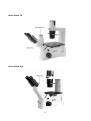
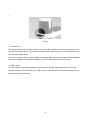
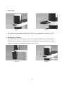
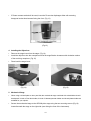
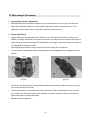
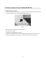
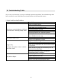
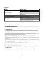
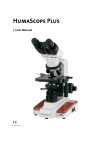
We are constantly endeavouring to improve our instruments and to adapt them to the requirements of
modern research techniques and testing methods. This involves modification to the mechanical
structure and optical design of our instruments.
Therefore, all descriptions and illustrations in this instruction manual, including all specifications are
subject to change without notice.
1
Content
I.
Nomenclature
4
1. Application
4
2. Nomenclature
4
3. Technical data
7
II. Setting-up the Instrument
8
1. Working Environment
8
2. Input voltage and power
8
III. Assembling the Microscope Input Voltage
10
1. Installing the bulb
10
1.1 Halogen bulb
12
1.2 LED module
12
2. Filter Holder
13
3. Mounting the Condenser
13
4. Installing the Objectives
14
5. Mechanical Stage
14
6. Mounting the Eyepieces
15
IV. Microscopic Procedure
16
1. Interpupillary Distance Adjustment
16
2. Diopter Adjustment
16
3. Coarse and fine focusing
17
4. Coarse focus torque adjustment
17
5. Change the illumination between Halogen and LED
18
6. Brightfield Microscopy
19
7. Phase-Contrast Microscopy
19
8. Filter selection
21
9. Auto power off function
21
V. Photomicrographic Procedure (Model AE2000 trinocular)
1. Brightfield photomicrography
23
23
2
VI. Troubleshooting Table
24
1. Optical and Operating Problems
24
2. Electrical
25
VII. Care and Maintenance
25
1. Lenses and Filters
25
2. Cleaning of Painted or Plastic Components
25
3. When Not in Use
26
4. Warning lable
26
3
I. Nomenclature
1. Application
AE2000 incorporates the Color Corrected Infinity Optical System (CCIS) that offers superior image
quality for the transmitted and reflected illumination in the application of Living organism and tissue
observation, Petri dish observation, Live cell in culture observation.
2. Nomenclature
Model AE2000
4
Model AE2000
5
Model AE2000 TRI
Model AE2000 Ergo
6
3. Technical data
Technical data
AE2000
AE2000 TRI
Optical system
AE2000 Ergo
Color-corrected infinity optics
Total Magnification
40X - 400X
360° rotatable Siedentopf with upper and lower position: upper position
Eyepiece tubes
offers approx. 40 mm extra viewing height
Interpupillary distance: 48 mm to 75 mm
Binocular 45° incline
Eyepiece
Trinocular 45°incline
N-WF 10X(ø20), wide field, high eye point
Nosepiece
Stage
Ergo incline: 45°± 15°
4x, inclined backwards
Fixed, Dimensions (width x depth): 200 x 239mm
Stage height 192mm
Verniers with numerical and alphabetic scale
Object guide
X direction: numerical scale, readable from right to left
Y direction: alphabetic scale
Plan-Achromat 4x, N.A. 0.1, W.D. 12.6mm
Plan-Achromat 10x, N.A. 0.25, W.D. 16.8mm
LWD Plan-Achromat 20x, N.A. 0.3, W.D. 4.7mm
Objectives
LWD Plan-Achromat 40x, N.A. 0.5, W.D. 3mm
Plan-Achromat PH 4x Ph0, N.A. 0.1, W.D. 12.6mm
Plan-Achromat PH 10x Ph1, N.A. 0.25, W.D. 4.1mm
LWD Plan-Achromat PH 20x Ph2, N.A. 0.3, W.D. 4.7mm
LWD Plan-Achromat PH 40x Ph2, N.A. 0.5, W.D. 3mm
N.A. 0.3, W.D. 72mm
Condenser
N.A. 0.4, W.D. 53mm
N.A. 0.5, W.D. 28mm
Coarse drive
42mm/rev.
Fine drive
0.2mm/rev.
Transmitted
6V/30W Halogen
illumination
3W LED
Dimension: W x D x H
217.5 x 556 x 497mm
7
II. Setting-up the Instrument
1. Working Environment
The location should be free from dust, moisture, chemical vapours and from mechanical vibrations.
Don't locate the instrument in bright or direct ambient light, in front of a lamp, or a will-lit bright wall. Best
image will be achieved without significant ambient light.
Environmental specification:
y
Indoor use
y
Altitude: Max 2000m
y
Ambient temperature: 15°C~ 40°C;
y
Maximum relative humidity: 75% for temperature up to 31°C decreasing linearly to 50% relative
humidity at 40°C
y
Supply voltage fluctuations: Not to exceed ±10% of the normal voltage
y
Pollution degree: 2 ( in according with IEC60664)
y
Installation/Overvoltage category: 2 (in according with IEC60664)
y
Air Pressure of 75kPa to 106 kPa
2. Input voltage and power
Automatic voltage selection works with electrical outlets worldwide. It is advised to always use a power
cord that is rated for the voltage used in your area and that has been approved to meet local safety
standards. Using the wrong power cord could cause fire or equipment damage.
In order to prevent electric fluctuation to the instrument electrics, always turn the power switch on the
instrument off before connecting the power cord.
This equipment must be used with UL60950-1 Listed power supply (E246759), MFR: LI TONG
ELECTRONICS CO., LTD. Model: LTE50E.S2.3.
y
Input Voltage: 12VDC
y
Input Power: 48W
y
Power adaptor input rating: 100-240Vac, 47-63Hz, 1A
8
Attention: The plug of power adaptor is the "disconnect device" for whole unit. To save energy and
environmental priciple, we recommend you to pull out the plug if you will not use the device in long time.
This device complies with Part 15 of the FCC Rules.
Operation is subject to the following two conditions:
(1) this device may not cause harmful interference, and (2) this device must accept any interference
received, including interference that may cause undesired operation.
9
III. Assembling the Microscope
1. Installing the bulb
y
In order to prevent electric shock always turn the power switch off (Fig.1) and unplug the power
cord (Fig.2) before replacing the bulb.
y
To remove lamphouse cover, press down lightly (1) and rotate counter clockwise (2). (Fig.3)
Power Switch (Fig.1)
Power Cord (Fig.2)
Lamp house Cover (Fig.3)
10
Firmly insert the bulb into the socket pinholes (Fig.4) until it reaches the limit, be careful not to tilt the
lamp when mounting. (Fig.5)
(Fig.4)
(Fig.5)
(Halogen Bulb)
y
When installing the halogen bulb, be care not to touch the glass surface of the bulb with bare
fingers to avoid fingerprints, grease, etc. Surface pollution can burn the bulb and reduce the
illumination provided by bulb. If surface is contaminated, wipe it clean using lens tissue or soft cotton.
(Fig.6)
(Fig.7)
(LED module)
y
Firmly insert the LED module into the socket pinholes until it reaches the limit. This is Motic patent
design to exchange LED module and halogen bulb on the same socket directly.
y
After the LED module installation (Fig.6), secure it with the clamp screw by 1.5mm hexagonal
screwdriver supplied with the microscope. (Fig.7)
y
Return lamphouse cover to original position and rotate clockwise to lock into place. The white paint
marked on the cover should face the user. (Fig.8)
11
y
(Fig.8)
1.1 Halogen bulb
The quartz halogen bulb, used as a light source, has higher luminance and colour temperature than
conventional tungsten lamps. The luminance of halogen bulb is approximately four times brighter than the
conventional tungsten lamps.
As long as the lamp voltage is kept constant, the halogen lamp maintains the same level of brightness
and colour temperature regardless of whether it is new or nearing the end of its life span.
1.2 LED module
The LED module is specially designed to be inserted into halogen bulb socket directly converting
halogen illumination to LED illumination. LED is more economical and environmental friendly and no
heat issue with a long life span.
12
2. Filter Holder
(Fig.9)
y
(Fig.10)
Filter holder is located under the lamphouse (Fig.9) for easy replacement of the filter. (Fig.10)
3. Mounting the Condenser
y
Mount the condenser on the dovetail mount of the condenser holder (Fig.11) with the aperture
diaphragm lever and index marks facing the front and secure it with the clamp screw by 2.5mm
hexagonal screwdriver supplied with the microscope. (Fig.12)
(Fig.11)
(Fig.12)
13
y
If Phase contrast method will be used, insert the Ph annular diaphragm slider with centering
hexagonal socket head screws facing the front. (Fig.13)
(Fig.13)
4. Installing the Objectives
y
Remove the stage insert from the stage. (Fig.14)
y
Install the objectives into the nosepiece so that the magnification increases with clockwise rotation
of the revolving nosepiece. (Fig.15)
y
Place back the stage insert.
(Fig.14)
(Fig.15)
5. Mechanical Stage
y
When using a 96-well plate or other petri dish,the mechanical stage combined with suited holder should
be adopted. 3 kinds of Petri dish holder, 2 kinds of Heamacytometer holder and 96 well plates holder are
available for your opinion.
y
Secure the mechanical stage to the AE2000 plain stage using the two mounting screws (Fig.16)
located beneath the stage on the right side (user facing the front of the instrument).
14
(Fig.16)
y
The specimen can be moved to the desired position by turning the X-axis knob and Y-axis knob.
6. Mounting the Eyepieces
y
Remove the dust caps from the eyepiece tubes.
y
Use the same magnification eyepieces for both
the eyes.
y
Insert each eyepiece into the eyepiece sleeve,
and tighten the clamp screws. (Fig.17)
y
Should the rubber eye guards are to be used,
fit them in the groove around the eyepiece.
1. Clamp screws (Fig.17)
15
IV. Microscopic Procedure
1. Interpupillary Distance Adjustment
y
Before adjusting the interpupillary distance, bring a specimen into focus using the 10x objective.
y
Adjust the interpupillary distance so that both the right and left field of view become one. This
adjustment will enable the user to observe the specimen with both eyes.
2. Diopter Adjustment
y
Diopter adjustment compensates for the differences in vision between the left and right eyes. In
addition to making observation through both eyes easier, this adjustment also reduces the extent to
which focusing is lost when the objective magnification is changed. In particular, this occurs when a
low magnification objective is used.
y
Before adjusting the diopter, bring a specimen into focus using the 10x objective.
y
Turn the diopter compensation ring on each eyepiece until the adjustment ring is adjusted to the“0”
position.
y
(Fig.18)
y
(Fig.19)
Position the 40x objective into the optical path and bring the specimen image into focus by turning
the coarse and fine focus knobs.
y
Position either the 4x or 10x objective into the optical path. Without adjusting the fine and coarse
focus knobs, turn the diopter rings on the eyepieces so that the specimen images in the left and
right eyepieces are focused individually.
y
Repeat the above step twice.
16
3.Coarse and fine focusing
y
Focusing function is realized with the coarse and fine focus knobs at the left and right of the
microscope stand.
y
The direction of vertical movement of the stage corresponds to the turning direction of the focus
knobs.
y
One rotation of the fine focus knob moves the stage 0.2mm up or down movement. The graduation
on the fine focus knob is 2 microns.
Please avoid following action:
y Never attempt either of the following actions, since doing so will damage the focusing mechanism.
y Rotate the left or right knob while holding the other.
y Turning the coarse and fine focus knobs further than their limit.
4. Coarse focus torque adjustment
y
To increase the torque, turn the torque adjustment ring located behind the left-hand coarse focus in
the direction of the arrow. To reduce the torque, turn the ring in the direction opposite.
1. Coarse Focus Torque Adjustment Ring
2. Coarse Focus Knob
(Fig.20)
17
3. Fine Focus Knob
5. Change the illumination between Halogen and LED
y
Attention:
Unplug the plug-in power unit from the power outlet to protect user from electric shock and allow for
a sufficient cool-down time of the6V 30W halogen lamp before you replace it.
y
Press down lightly and rotate counter clockwise and remove lamphouse cover. (Fig.21)
(Fig.21)
y
Remove the bulb from the socket pinholes.
Halogen bulb (Fig.22)
y
LED (Fig.23)
Installing the new bulb into the socket pinholes, until it reaches the limited, be careful not to tilt it
when mounting.
y
If installing the halogen bulb, do not touch the glass surface of the lamp with bare fingers. Doing so
will cause fingerprints, grease, etc., to burn onto the lamp surface, reducing the illumination
provided by the bulb. If surface is contaminated, wipe it clean using lens or soft cotton.
y
Return lamphouse cover to original position and rotate clockwise to lock into place. The white paint
marked on the cover should face the user.
y
The same halogen bulb holder can be used for both LED illumination module.
18
6. Brightfield Microscopy
y
Set the Phase annular diaphragm slider in the centre position without phase annular diaphragm.
(Fig.24)
y
Bring the specimen image into focus.
y
The condenser aperture diaphragm is provided for adjusting the numerical aperture (N.A.) of the
illuminating system of the microscope. It is important
because it determines the resolution of the image,
contrast, depth of focus and brightness.
y
Stopping down the aperture diaphragm will lower the
resolution and brightness but increase the contrast
and depth of focus. By stopping down the N.A. of the
condenser to 2/3 of the N.A. of the objective, a good
image of suitable contrast will be obtained.
(Fig.24)
7. Phase-Contrast Microscopy
y
Phase contrast objectives are labelled “Ph”: Ph0; Ph1; Ph2.
y
For phase contrast microscopy, be sure to use the annular diaphragm that has the same phase
label as the objective, despite of the magnification of the objective.
y
Move the aperture diaphragm lever on the condenser to fully open position.
Always fully open the aperture diaphragm for phase contrast microscopy. If aperture diaphragm is
closed, it will obstruct the annular diaphragm and the phase contrast effect cannot be obtained.
y
Bring the 10x (Ph1) objective into optical path.
y
Position the Phase annular diaphragm slider to Ph1.
y
Position the Phase annular diaphragm slider to Ph0 when using 4x objective.
And position the Phase annular diaphragm slider to Ph2 when using 20x (Ph2) or 40x (Ph2)
objective.
y
Remove either eyepiece from the eyepiece tube and insert the phase centering telescope instead.
(Fig.25)
y
Rotate the eyepiece of the centering telescope to focus on both the phase plate image of the
objective and the annular diaphragm image of the phase slider.
19
(Fig.25)
y
If the objective phase plate and the annular of the slider do not coincide, use the two hexagonal
screwdrivers (1.5mm) supplied with the microscope (Fig.26) to bring the slider annular ring to the
centre of the phase plate (Fig.27), so that the image of the annular diaphragm is concentric with the
phase plate image.
If the slider annular ring image is diverged from the phase plate image in the objective, a low phase
contrast image will result.
(Fig.26)
y
(Fig.27)
For phase contrast microscopy at the maximum contrast, use GIF (Green interference filter) in the
optical path.
y
Change the annular diaphragm if necessary, noted that place it into phase slider in correct direction
(Fig.28) and use 2 hexagonal screwdrivers (1.5mm) supplied to bring the annular ring to the center
of the phase slider (Fig.29).
y
Put the phase slider back to condenser
20
(Fig.28)
(Fig.29)
8. Filter selection
Filter holder could hold two pieces of filters
Filter type
ND (Neutral Density) filter
GIF (Green Interference) filter 546nm
Blue filter
Procedure
For intensity adjustement in photomicrography
For phase contrast and contrast adjustment with
black and white film
For general microscopy and colour
photomicrography
9. Auto power off function
(Fig.30)
21
y
There is a auto power off switch locates above the left focusing knob.
y
When “auto” is selected, the blue pilot lamp will be turned on. It indicates auto power off status.
(Fig.30)
y
If “auto” is selected, the light will automatically turn off after 15 minutes when no user in front of the
unit. When the user return to the microscope, the light will resume immediately with the infra sensor
sense someone in front of the microscope.
*
Never attempt to switch directly between "on" and "auto".
The buffer "off" is necessary between auto power off mode and normal mode.
22
V. Photomicrographic Procedure (Model AE2000 TRI)
1. Brightfield photomicrography
y
The optical path selector knob (Fig.31) can be used to select the optical path to either the Binocular
tube 100:0 or Binocular tube / vertical tube 20:80 (observation: photo).
(Fig.31)
y
Before starting photomicrography, check the following:
The condenser is centered.
The condenser annular diaphragm is centred.
The field of view diaphragm is stopped down to slightly just outside the edge of the field of view.
y
For photomicrographic procedures, refer to the manual of the specific camera being used.
23
VI. Troubleshooting Table
As you use your microscope, you may occasionally experience a problem. The troubleshooting table
below contains the most frequently encountered problems and their possible causes.
1. Optical and Operating Problems
Problem
Possible Cause
Bulb not installed properly
Filter slider in intermediate position
Phase slider not in click-stop position
Vignetting or uneven brightness in the field
Incorrect condenser mounting
of view or field of view only partially visible
Aperture diaphragm closed too far
Revolving nosepiece not clicked into position
Optical path selector lever in intermediate position
(Mod. AE2000 trinocular only)
Dust or dirt in field of view
Aperture diaphragm closed too far
Dust or dirt on specimen’s surface
Brightfield objective being used
Phase annular diaphragm not in optical path
Image quality:
No image under phase contrast or details
cannot be viewed
Phase annular diaphragm and objective phase symbol
do not match
Slider annular ring image has moved away from the
objective phase plate image
Thickness of specimen holder is outside the
compensating range of objective
Interpupillary distance not adjusted
Eye strain or fatigue
Diopter adjustment not made
Inadequate illumination
Field of view of left and right eyepiece differ
24
2. Electrical
Problem
Possible Cause
Power supply not plugged in
Lamp does not light
Lamp not installed
User left more than 15 minutes under auto mode
Lamp burnt out
Inadequate brightness
Specified lamp not being used
Lamp blows out immediately
Specified lamp not being used
Connectors are not securely connected
Lamp flickers
Lamp near end of service life
Lamp not securely plugged into socket
VII. Care and Maintenance
1. Lenses and Filters
y
To clean lens surfaces or filters, first remove dust using an air blower. If dust still persists, use a soft /
clean brush or gauze.
y
A soft gauze or lens tissue lightly moistened with the mixture of alcohol and ether ( ratio: alcohol : 3 and
ether: 7) should only be used to remove grease or fingerprints.
y
Use the mixture of alcohol and ether ( ratio : alcohol : 3 and ether: 7) to clean immersion oil.
y
Use the mixture of alcohol and ether ( ratio : alcohol : 3 and ether: 7) only to remove immersion oil from
objective lenses.
y
Because the mixture of alcohol and ether ( ratio : alcohol : 3 and ether: 7) is highly flammable, be careful
handling around open flame.
y
Do not use same area of gauze or lens tissue to wipe more than once.
2. Cleaning of Painted or Plastic Components
y
Do not use organic solvents (thinners, alcohol, ether, etc.). Doing so could result in discolouration or in
the peeling of paint.
y
For stubborn dirt, moisten a piece of gauze with diluted detergent and wipe clean.
y
For plastic components, only moisten a piece of gauze with water and wipe clean.
25
3. When Not in Use
y
When not in use, cover the instrument with vinyl dust cover and store in a place low in humidity
where mould is not likely to form.
Store the objectives, eyepieces and filters in a container or desiccator with drying agent.
Note:
If equipment is used in a manner not specified by the manufacturer, the protection provided by the
equipment may be impaired.
4. Warning lable
The following warning labels (or symbols) are found on the microscope, Study the meaning of the
warning labels (or symbols) and always use the equipment in the safest possible manner.
Warning Label / Symbol
Explanation
Indicates that the surface becomes hot, and
should not be touched with bare hands.
CAUTION! Risk of danger. (See user manual)
Proper handling of the microscope will ensure years of trouble free service.
If repair become necessary, please contact your Motic agency or our Technical Service directly.
26