1
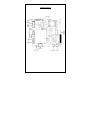
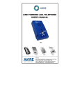
LINE POWERED ADA TELEPHONE
USER’S MANUAL
PNB-R
Avire Inc
415 Oser Avenue, Suite Q, Hauppauge, New York 11788
Phone: 631 864 3699 Toll Free: 800 527 9156
Janus is a brand of Avire
Fax: 631 864 2631 Email: [email protected]
TABLE OF CONTENTS
SECTION
PAGE
INSTALLATION……………………………………………………………….3
P.C. BOARD DIAGRAM……………………………………………………..4
PROGRAMMING SET-UP METHODS…………………………………….5
PROGRAMMING INSTRUCTIONS………………………………….……..6
OPTIONAL PROGRAMMING INSTRUCTIONS…………………………..6
LIST OF COMMANDS FOR PROGRAMMING MODE.…………………..7
LIST OF COMMANDS FOR CONVERSE MODE……..…………………..8
OPERATING INSTRUCTIONS……………………………………….……..9
AUXILIARY OUTPUTS INFORMATION..………………………………….11
BATTERY & POWER SUPPLY INFORMATION………………………….11
TROUBLESHOOTING GUIDE..…………………………………………….12
SPECIFICATIONS……………………………………………………………15
FCC NOTICE………………………………………………………….………16
WARRANTY POLICY………………………………………………….……..17
RETURN POLICY…………………………………………………………….17
2
Installation
1. Remove the old Rath-Smart Phone board from Plastic bracket.
2. Remove the old Battery from plastic Bracket.
3. Install the new PNB-R board into plastic Bracket keeping the board
orientation the same as the Rath-Smart Phone.
4. Plug in the External Call button to P2 SWITCH connector.
5. Plug in the External LED to P6 connector.
6. Plug in the External Speaker to P4 SPK connector.
7. Plug in the External Microphone to the P3 MIC connector.
8. Attach phone line to terminal block at P1 (TELCO) phone jack.
9. Optional Step: If you will be using the AUX2 phone line monitoring
option of the phone you must also connect 24V AC/DC power supply to
the P9 Power connector and install a jumper at the LM pins.
NOTE: The PNB-R Phone is phone line powered. If a battery is needed
attach an 8.4V NiMH or a Standard 9V-Alkaline battery to the Battery
Lead of the board. Do not use a 9V-Alkaline battery if you are
connecting a power supply to the P9 power connector. (See Battery &
Power supply section for more information)
CAUTION: To reduce or eliminate any possible interference, it is highly
recommended that the wiring used inside the traveling cable for
the incoming phone line be a 20-22 AWG twisted shielded pair
with the shield grounded at the elevator controller end only. Any
terminations or splices between the elevator controller and the
elevator phone should have the shield carried through the
termination of splice and not grounded at that point.
3
PC Board Diagram
4
Programming Set-Up Methods
There are two methods of SETTING UP the Hands-Free elevator phone
for programming. Select the one applicable to your situation as described
below.
NOTE: THE TELEPHONE LINE PROVIDED MUST BE A TOUCH-TONE
LINE.
The Hands-Free telephone can be programmed at any location and then
installed in the elevator cab. The phone will retain its programming
without the need for a battery.
Method A: Calling the Elevator Phone to Program it.
1.
2.
3.
4.
From any touch tone phone call the phone number to which the
elevator phone is connected.
After four rings the elevator phone will turn on automatically and you
will hear a diddle-diddle-diddle sound.
Go to the “PROGRAMMING INSTRUCTIONS” section.
After programming the ADA phone, you should test it by pressing the
“CALL” button. The test will assure the phone is functioning correctly
and as programmed.
Method B: Using the Keypad on the board to program it.
1.
2.
3.
4.
5.
6.
7.
8.
Disconnect the phone line from the P1 (TELCO) phone jack.
Connect a 9-volt battery to the battery lead of the board. (See diagram
of phone board)
Press the “PROGRAM” button next to the keypad.
Make sure that the red light of the phone turns on. If it does not, go
back to step 3 and start again.
The elevator phone will turn on and you will hear a diddle-diddle-diddle
sound.
Go to the “PROGRAMMING INSTRUCTIONS” section.
When you have completed the Programming of the phone you can
unplug the 9-volt battery.
After programming the ADA phone, you should test it by pressing the
“CALL” button. The test will assure the phone is functioning correctly
and as programmed.
5
Programming Instructions
1.
2.
3.
4.
5.
6.
7.
8.
9.
10.
11.
12.
13.
Choose programming setup method A or B.
Enter # 94851 to get into programming mode. Listen for three beeps.
NOTE ONE: Enter touch tone digits slowly and deliberately.
NOTE TWO: Once you are in programming mode, you can perform
any programming step in any sequence as long as you get three
beeps after your programming entry.
Enter # 0 (enter the first phone number to be programmed) * #. Listen
for three beeps. EXAMPLE: # 0 5551212 * #.
NOTE: If you are on a phone line that requires a "9" or another digit to
call the answering service, enter a # after the 9. This will insert a 4
second pause. EXAMPLE: # 09 # 5551212 * #.
Enter # 1 (enter the second telephone number to be programmed) * #.
(Optional)
Enter # 2 (enter the third telephone number to be programmed) * #.
(Optional)
Enter # 3 (enter the fourth telephone number to be programmed) * #.
(Optional)
Enter # 4 (ID Code) *# (Optional)
Enter # 7 and listen for the single beep. At the beep, record the
location message by speaking into the touch-tone phone handset or
into the microphone of the HFP phone when using the keypad to
program. Enter 0 to end. If you want to listen to the location message
without changing it, enter # 8.
Enter # * 1180183 * # and listen for three beeps. (Enables Voice
prompt messages)
Enter # # to exit programming and hang up the phone.
Optional Programming Instructions
PURPOSE: To Eliminate Autodialing:
To disable the dialer from dialing a phone number. (Used on a Ring Down
telephone line)
Enter # 94851 and listen for three beeps.
Enter # 0 * #, listen for three beeps, enter # 1 * #, listen for three beeps.
Enter # 2 * #, listen for three beeps, enter # 3 * #, listen for three beeps.
Enter # * 1180180 * #, listen for three beeps. (Optional)
Enter # # and hang up.
PURPOSE: To Disable the Voice Prompt Message:
To disable the voice prompt from saying: "Elevator call at the tone press
one to talk, press two for Location".
Enter # 94851 and listen for three beeps.
Enter # * 1180180 * #, listen for three beeps.
Enter # # and hang up.
CAUTION: This option cannot be used with two or more number dialing.
6
PURPOSE: To Disable Voice Prompt Message and Delay Voice
Location Message:
To disable the voice prompt and have the location message play
automatically every 19 seconds.
Enter: # 94851 and listen for three beeps.
Enter: # * 1180185 * # and listen for three beeps.
Enter: # # and hang up.
PURPOSE: To Enable Voice Prompt Message: (DEFAULT)
To enable the voice prompt message to say: "Elevator call at the tone press
one to talk, press two for Location".
Enter # 94851 and listen for three beeps
Enter # * 1180183 * # and listen for three beeps.
PROGRAM LOCATION MESSAGE (SEE STEP 7 IN PROGRAMMING
INSTRUCTIONS)
Enter # # and hang up.
List of Commands for *Programming Mode
*Note: The phone enters Programming mode after completing step 2
of the Programming instructions.
#0 1st Phone Number *#
#1 2nd Phone Number *#
#2 3rd Phone Number *#
#3 4th Phone Number *#
#4 Identification Code *#
#5 XXXX *# - Sets New Programming Access Code (Default XXXX=4851)
#6 XXXX *# - Confirms New Programming Access Code
#7
- Records Location Message
#8
- Plays back Location Message
#* 1 XXX Y W Z *# - setup code (Default is: #* 1 180 1 8 3 *#)
o
XXX – Call Timer [000,060-990], 000=Disable timer
o
Y – Push Button Control [0-2]
[0] – PUSH ON=TURN ON / PUSH AGAIN=PLAY MSG
[1] – PUSH ON=TURN ON / PUSH AGAIN=TURN OFF
[2] – PUSH&HOLD=TURN ON / RELEASE=TURN OFF
[3-8] – PUSH AND HOLD TO TURN ON FOR Y AMOUNT
OF SECONDS TO MAKE A CALL. IF PUSH FOR LESS
THEN Y AMOUNT OF SECONDS TURN OFF/ PUSH
AGAIN=TURN OFF
o
W – Unit ID [1-8]
o
Z - Voice Mode [0,3 or 5]
**43 XX *# -Ring Time (for outgoing calls) (18-60 range, 50 is default)
**44 X *# - AUX1 behavior, 0=disabled (Default), 1 = red led, 3 = VCC
mode.
**45X*#- Redial, 0=disabled (Default), 1=Dial the number 1 more time,
2=Dial the number 2 more times.
7
**8 XX *# - Set Language (1 = English: default, 2 = Spanish, X= [1-2] (must
have 2 digits)
Note: **8XX*# - It will play both messages according to the order specified.
(Ex// **812*# = English then Spanish or **821*# = Spanish then English)
Note: If second message is not used enter ‘0’ for that message. For
Example if you want to set to play English only you must program: **810*#.
**7 0 *# - Ring-Thru Converse Mode. (Default) With this setting, the HFP
will automatically enter two way communication after it has answered an
incoming call.
**7 1 XXXX *# - Hang Up Converse Mode – Set Access Code. With this
setting when the user calls in he/she will hear 3 beeps and has 5 seconds
to enter the 4 digit password set by *71. If he/she does not or he enters the
wrong code he will hear a long beep and the phone will turn OFF. If he/she
enters the correct code a diddle-diddle sound will be heard and 2 way
communication will be established. The speaker and microphone will both
be muted until the correct code is entered.
## - Exits programming mode
**90 *# - Sets the following Default Values:
o
#*1180183*# - Default Setup Code.
o
**43 50 *# - Ring Time (for outgoing calls)
o
**45 0*# - Disable Redial
o
**70*# - Ring Thru Converse Mode
List of Commands for *Converse Mode
*Note: The phone enters Converse mode when pressing the program
button above the keypad or when receiving an incoming call)
0 or #9 - ACK conversation (blink LEDs depending on LED mode)
1 - Enters Two Way Communication + ACK conversation
2 - Plays Location Message & Alert Message
3 - Renew Call Timer
# - Mutes the microphone if no other digit is pressed within 3 seconds.
Any other digit including “#” immediately turns it back on.
Note: The microphone is not muted while in Keypad mode.
#0 - Plays back 1st Phone Number in DTMF tones.
#1 - Plays back 2nd Phone Number in DTMF tones.
#2 - Plays back 3rd Phone Number in DTMF tones.
#3 - Plays back 4th Phone Number in DTMF tones.
#4 - Plays back Unit ID in DTMF tones
#6 - Plays Firmware Version in DTMF tones
##0 - Plays back 1st Phone Number in Voice.
##1 - Plays back 2nd Phone Number for in Voice.
##2 - Plays back 3rd Phone Number for in Voice.
##3 - Plays back 4th Phone Number for in Voice.
8
##4
##6
#*
*0
- Plays back Unit ID in Voice.
- Plays Firmware Version in Voice.
- Hangs Up with 2-3 seconds delay
- Hangs the phone up with no delay.
8-Decrease speaker level (3 levels available: Normal, Medium & High)
9-Increase speaker level (3 levels available: Normal, Medium & High)
**8-Decrease microphone level (3 levels available: Normal, Medium & High)
**9-Increase Microphone level (3 levels available: Normal, Medium & High)
Note: Three beeps indicate that the speaker or microphone has been
adjusted by one level. The Normal level is the default and it is saved even if
the power is removed from the unit.
Operating Instructions
A: Trapped Passenger Calling Out
1. Passenger presses "CALL" button. Red LED turns “ON”.
2. Passenger hears dial tone and dialing of first phone number.
3. Passenger hears intermittent ringing.
4. Passenger hears a tone two seconds after elevator phone dials and
every 7 seconds until the operator responds to the call.
5. If first phone number is not answered within approximately 50
seconds, the elevator phone will hang up and dial the second phone
number. The same sequence of events will occur for any additional
phone numbers the phone is programmed to call.
6. Once the receiving operator responds to the call with a touch-tone digit
the passenger and the operator will be able to communicate.
7. When the Red LED flashes, the operator can request the passenger to
press the "CALL" button again. This action will send an audible signal
to let operator know that someone is actually stuck in the elevator and
not just a prank call. This action is normally only important for
someone who cannot speak.
B: Responding Operator - with Prompt Message Enabled
1. Operator hears ringing of incoming call from elevator and answers call.
2. Operator hears a repeating message from the elevator phone stating
"ELEVATOR CALL, AT THE TONE PRESS ONE TO TALK, PRESS
TWO FOR LOCATION". The message will keep repeating until the
operator presses a "1" or "2" after the tone on their touch-tone phone.
3. The passenger does not hear any voice messages.
4. Normally the operator should press "1" after the touch-tone at the end
of the message to quickly establish two way voice communication with
the trapped passenger.
5. At any time the operator can press "2" to hear the location of the
elevator.
9
6.
In elevators with a lot of background noise, the operator can press # to
mute the microphone. Entry of any other digit will re-enable the
microphone.
7. At the end of the location message another message will be heard by
the operator that Says: "PRESS ZERO TO ALERT PASSENGER OF
RESCUE."
8. When the operator presses "0" on their touch-tone phone they will hear
three beeps. The Red light flashes. At this point the operator has
acknowledged the call. The passenger knows that the call has been
received because wording printed on the car operating panel or the
phone states “BLINKING INDICATES CALL IS ANSWERED”
9. The operator can request that the passenger press the "CALL" button
again. If the passenger presses the button, the operator will hear a
diddle-diddle-diddle sound. For the operator, this means that there is a
passenger in the elevator.
10. Prior to the phone turning off (normally 3 minutes), the operator will
hear this message twice, "TO AVOID DISCONNECT PRESS THREE
NOW"
11. If the operator presses "3" on their touch tone phone within ten
seconds after this message, the elevator phone will stay on for another
three minutes. The message will be repeated every three minutes for
the duration of the call so that the operator can keep the passenger on
the line until help arrives or as long as needed.
12. Operator presses *0 to hang up the elevator phone.
Alternate B - with Delayed Location Message - Voice Mode 5
ALL OPERATING STEPS ARE THE SAME EXCEPT
1. Operator answers incoming call and begins talking to passenger.
2. Within 17 seconds after the call is dialed, the operator will hear the
location message followed by this message: "PRESS ZERO TO
ALERT PASSENGER OF RESCUE."
3. Both messages will repeat every 20 seconds until the operator enters
"0".
Operator Calling Into Elevator Phone
1.
2.
3.
Operator dials the phone number of the elevator phone and hears
ringing.
After four rings the elevator phone turns on automatically and
operator will hear diddle-diddle-diddle sound.
At this time the operator and passenger can talk. All other operations
stay the same.
Passenger Receiving Call from Operator
1.
2.
Passenger hears elevator phone ringing. Phone turns on automatically
after 4 rings
When elevator phone turns on the passenger and operator can
communicate.
10
Auxiliary Outputs Information
AUX1: The AUX1 output by default will not be active (Open). If the user will
like to activate this output he or she must program code: **44 X *# - which
controls the AUX1 behavior. The letter X on this code could be substituted
by 0, 1, or 3.
0 = Disabled – The AUX1 will stay OPEN.
1 = Red LED mode – The AUX1 will Close when the Red LED turns ON
and Open when the
Red LED turns “OFF”.
3 = VCC mode – The AUX1 will Close when the Phone turns ON and Open
when the Phone turns “OFF”.
AUX2: The AUX2 output is used for phone line monitoring. When a good
Phone line is connected to the unit this output is normally open. If it detects
a failure on the telephone line or if the line is shorted or disconnected this
output will close within 5 minutes.
Note: AUX2 will only work if the optional 24V AC/DC power supply is
connected to the P9 connector and a jumper is installed at the LM
connector on the board.
Battery & Power Supply Information
The following information explains how to determine when a battery or
power supply is needed or when to use a specific type of battery:
You will need a 9V battery or a 24V AC/DC power supply with 8.4V
NiMH battery when:
1.
2.
The phone drops off the telephone line without completing the call.
There is more than one phone on the same telephone line and there is
a need to call back to a specific elevator phone, or if all elevator
phones need to be “ON” at the same time.
ALKALINE BATTERY: Can be used on all phone lines. The battery will
need to be checked every 6 months. An AC connection is not required and
the battery cannot be trickle charged.
LITHIUM BATTERY: Can be used on all phone lines. The battery will need
to be checked every 12 months. An AC connection is not required and the
battery cannot be trickle charged.
24VDC POWER SUPPLY: Can be used on all phone lines. The 8.4V NiMH
battery supplied with the power supply will need to be checked every 12
months. An AC connection is required and the battery will be charged by
the power supply connected to the P9 connector of the board. The P9
connector is not polarity sensitive.
CAUTION: DO NOT use an alkaline or lithium battery when the power
supply is connected to the P9 connector.
11
Troubleshooting Guide
Always visually check the phone for loose or shorted wires, physically
damaged or missing components. The phone will not work on a Digital
phone line. It will only work on an Analog phone line or an Analog port
from a digital phone system.
Problem: Phone would not turn ‘ON’
Possible Cause:
•
Check phone line connection
•
Check phone line voltage (Normal C.O. line 48-52VDC or 2035VDC – Internal systems)
•
Try connecting a fully charged 9-Volt battery.
•
Make sure phone line is connected to the TELCO P1 modular
phone jack. (See P.C. Board Diagram)
•
Check if unit is pulling down line voltage (You should read the
same as the phone line voltage)
•
Check voltage at controller
•
Check button connection
•
Disconnect Call Button wires and try shorting button connection
at P2.
Problem: Phone Dials Incorrect number
Possible Cause:
•
Check number programmed into phone
•
Plug a phone in the jack and call the same number you are trying
to program to see if you can call out.
•
Check to see if the phone is on a ring down line
•
Check to see if another auto dialer is on the line and remove it
•
Reprogram unit
Problem: Low or No sound thru speaker
Possible Cause:
•
Check speaker connection (See P.C. Board Diagram)
•
Try calling into unit and speaking to person in the car
•
Try adjusting the Speaker volume by calling into the phone and
when it answers press “9” twice to adjust the volume to the
maximum level.
•
Check mounting of the unit.
Problem: Noise on the line
Possible Cause:
•
Check if twisted shielded pair was used
•
Check to see if shield was connected to ground at the controller
end only
•
Measure AC voltage on line, should be zero
12
•
•
•
Check button connection
Try a spare pair of wires thru traveling cable
Check if wire is running thru hoist way by itself
Problem: Phone dials out but has broken communication
Possible Cause:
•
Check if voice prompt message is being stopped
•
Check if there is loud background noise in cab
•
Check location of microphone
•
Check mounting of unit
•
Try adjusting the Speaker and microphone volumes. (See Page
9)
•
Check mounting of the unit.
•
Check to see if person-answering call is using a handset.
Headsets that are not properly adjusted, could cause problems
Problem: Phone cannot be programmed
Possible Cause:
•
Try holding down keys slowly and deliberately
•
Try disconnecting the speaker. (See P.C. Board Diagram)
•
Make sure you are using a touchtone phone
•
If you are using a cell phone do not stand in the car
•
Check if phone is hearing tones (see if Red LED flickers when a
DTMF tone is received)
•
Check if twisted shielded pair was used
•
Check to see if shield was connected to ground at the controller
end only
•
Measure AC voltage on line, should be zero voltage
•
The phone will only work on an Analog phone system and not
digital.
Problem: Phone rings busy
Possible Cause:
•
Check if other devices are on the line
•
Check where phone line is properly connected to the unit
•
Check voltage on phone line
•
Check polarity on phone line
•
Make sure unit is off
•
Remove our unit from the line to see if line is still busy
Problem: Phone does not ring
Possible Cause:
•
Check phone line connection
•
Check ring voltage (min. 40VAC RMS)
13
•
Check phone line ringing with a touch-tone phone. (Disconnect
phone line from TELCO P1 phone jack and plug it to a standard
touch-tone phone
•
Problem: Phone Turns ‘ON’ by itself.
Possible Cause:
•
Check phone line on-hook DC voltage. The voltage should be
steady 24-52VDC
•
Check phone line on-hook AC voltage. The voltage should be
less then 1VAC.
•
Check push-button. The button should be a normally open dry
contact.
If you have questions or problems, please call Avire technical support
for assistance at 1-800-527-9156 or scan the QR code below using
your smart phone to be connected to our Automated Programming
System. (APS-Tel: 631-864-4759)
Notes:
____________________________________________________________
____________________________________________________________
____________________________________________________________
____________________________________________________________
____________________________________________________________
____________________________________________________________
____________________________________________________________
____________________________________________________________
____________________________________________________________
____________________________________________________________
____________________________________________________________
____________________________________________________________
____________________________________________________________
____________________________________________________________
____________________________________________________________
____________________________________________________________
____________________________________________________________
____________________________________________________________
____________________________________________________________
____________________________________________________________
____________________________________________________________
____________________________________________________________
14
Specifications
Input connections: One shielded twisted pair communication cable
(Shield should be grounded at the controller only)
Phone line requirements: Standard (analog) loop start voice grade touchtone telephone line, PBX or key system station analog telephone line.
Optional AC adapter:
24V AC/DC @ min. 250mA
Power required:
on-hook 0 ma
Power required:
off-hook 20 to 30 ma
Phone line voltage:
on-hook 24 to 70VDC (nominally 48VDC)
Phone line voltage:
off-hook 8 to 20VDC (nominally 12VDC)
Ring Sensitivity:
40 - 120VAC RMS
Dialing:
Frequency)
DTMF (Dual Tone Multi
Frequency Response:
550Hz - 3400Hz, +/- 3db.
Operational Loop impedance:
600 ohms
FCC Registration:
US: NLFTE03B25668
Ringer Equivalency Number:
0.3B
15
FCC Notice
The EMS phone complies with Part 68 of the FCC Rules and the requirements
adopted by the ACTA. On the bottom of the Printed Circuit Board of this
equipment is a label that contains, among other information, the FCC Registration
Number and Ringer Equivalence Number (REN) for this equipment. If requested,
this number must be provided to the telephone company.
The REN is used to determine the number of devices that may be connected to a
telephone line. Excessive RENs on a telephone line may result in the devices not
ringing in response to an incoming call. In most but not all areas, the sum of RENs
should not exceed five (5.0). To be certain of the number of devices that may be
connected to a line, as determined by the total RENs, contact the local telephone
company. For products approved after July 23, 2001, the REN for this product is
part of the product identifier that has the format US:AAAEQ##TXXXX. The digits
represented by ## are the REN without a decimal point (e.g., 03 is a REN of 0.3).
For earlier products, the REN is separately shown on the label.
If the terminal equipment, NLFTE03B25668 causes harm to the telephone network,
the telephone company will notify you in advance that temporary discontinuance of
service may be required. But if advance notice isn't practical, the telephone
company will notify the customer as soon as possible. Also, you will be advised of
your right to file a complaint with the FCC if you believe it is necessary.
The telephone company may make changes in its facilities, equipment, operations
or procedures that could affect the operation of the equipment. If this happens the
telephone company will provide advance notice in order for you to make necessary
modifications to maintain uninterrupted service.
If trouble is experienced with this equipment, NLFTE03B25668 for repair or
warranty information, please contact Avire at 1-800-527-9156 or visit us at
www.januselevator.com. If the equipment is causing harm to the telephone
network, the telephone company may request that you disconnect the equipment
until the problem is resolved.
Connection to party line service is subject to state tariffs. Contact the state public
utility commission, public service commission or corporation commission for
information.
WHEN PROGRAMMING EMERGENCY NUMBERS AND (OR) MAKING
TEST CALLS TO EMERGENCY NUMBERS:
1) Remain on the line and briefly explain to the dispatcher the reason for the call.
2) Perform such activities in the off-peak hours, such as early morning or late
evenings.
16
Warranty Policy
Avire Inc. warrants its products to be free from defect in materials and
workmanship under normal use and service for 24 months from date of
purchase. Seller’s obligation shall be limited to repairing or replacing, at its
option, free of charge for materials or labor any product which proves
defective in materials or workmanship under normal use and service. Avire
shall not be responsible for any damage to the unit incurred during
installation. Seller shall have no obligation under this Limited Warranty or
otherwise if the product is altered or improperly repaired or serviced by
anyone other than Avire factory service. For warranty service, contact Avire
at 631-864-3699 or 800-527-9156.
THERE ARE NO WARRANTIES, EXPRESS OR IMPLIED, OF
MERCHANTABILITY, OR FITNESS FOR A PARTICULAR PURPOSE OR
OTHERWISE, WHICH EXTEND BEYOND THE DESCRIPTION ON THE
FACE HEREOF. IN NO CASE SHALL SELLER BE LIABLE TO ANYONE
FOR ANY CONSEQUENTIAL OR INCIDENTAL DAMAGES FOR BREACH
OF THIS OR ANY OTHER WARRANTY, EXPRESS OR IMPLIED, OR
UPON ANY OTHER BASIS OF LIABILITY WHATSOEVER, EVEN IF THE
LOSS IS CAUSED BY THE SELLER’S OWN NEGLIGENCE OR FAULT.
Return Policy
During installation, if a product does not appear to function properly the
installer must call the Avire Technical Support Unit at (800) 527-9156,
Monday through Friday. If the technician determines that the product is not
functioning, an RA (Return Authorization) number will be issued, allowing
the installer to return the product directly to Avire for repair, replacement or
credit. Returns with no fault found, will result in a bench charge plus
shipping costs. Returns without an RA number will result in a restocking
charge of 25% or more plus shipping costs.
17