1
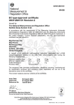
(UK/0126/0082) MI-006 United Kingdom of Great Britain and Northern Ireland Certificate of EC type-examination of a measuring instrument Number: UK/0126/0082 issued by the Secretary of State for Business, Innovation and Skills Notified Body Number 0126 In accordance with the requirements of the Measuring Instruments (Automatic Catchweighers) Regulations 2006 (SI 2006/1257) and the Measuring Instruments (NonPrescribed Instruments) Regulations 2006 which implement, in the United Kingdom, Council Directive 2004/22/EC, this certificate of EC type-examination has been issued to: Avery Weigh-Tronix Ltd Foundry Lane Smethwick West Midlands B66 2LP United Kingdom in respect of an automatic catchweigher comprising a controller designated the GSE 60Series, appropriate conveyors, pack detection and pack flow management devices, and a weighing unit comprising a load receptor and associated load cell(s) and having the following characteristics: Maximum capacity Minimum capacity Scale interval Number of scale intervals Accuracy class Dependant on application Min ≥ 20 e e ≥ 0.1 g n ≤ 6000 Y(a) The necessary data (principal characteristics, alterations, securing, functioning etc) for identification purposes and conditions (when applicable) are set out in the descriptive annex to this certificate. Signatory: for Issue Date: 08 October 2010 Valid Until: 07 October 2020 Reference No: T1108/0057 P R Dixon Chief Executive National Weights & Measures Laboratory (Part of National Measurement Office) Department for Business, Innovation & Skills Stanton Avenue Teddington Middlesex TW11 0JZ United Kingdom Descriptive Annex 1 INTRODUCTION This pattern of an automatic catchweighing instrument, comprising a controller designated the GSE 60-Series, appropriate conveyors, pack detection and pack flow management devices, and a weighing unit comprising a load receptor and associated load cell(s), is designed to operate as an automatic weight or weight/price labeller (Category Y). The instruments are designed to weigh packs statically. Sufficient time must be allowed for the static weight to be correctly taken for each application; a maximum conveyor speed must be determined, secured and checked at verification to ensure that the errors in automatic operation are less than the MPEs. Pricing, pack and labelling information is stored in files called PLUs selectable by the operator for the commodity or labels being processed. Labels are printed for the above transaction data and are applied to the packs automatically. Alternatively, the measurement data can be stored using the Data Storage Device. The data may be transmitted to a host computer for use in other applications, beyond the scope of this approval. 2 FUNCTIONAL DESCRIPTION 2.1 Mechanical 2.1.1 The instrument comprises a frame on which are mounted the modular conveyor sections (typically in-feed, weighing, out-feed). The conveyors’ type, number, size and shape are not restricted. 2.1.2 The instrument is designed to be permanently installed and fitted with a level indicator located on the weigh platform. 2.1.3 Weigh platform 2.1.3.1 The weighing device comprises a number of single strain gauge load cells fitted to the weigh platform. Any compatible load cell(s) may be used providing the following conditions are met: − There is a respective OIML Certificate of Conformity (R60) or a test certificate (EN45501) issued for the load cell by a Notified Body responsible for type examination under Directive 2009/23/EC. − The certificate contains the load cell types and the necessary load cell data required for the manufacturer’s declaration of compatibility of modules (WELMEC 2, Issue 5, May 2009), and any particular installation requirements. A load cell marked NH is allowed only if humidity testing to EN45501 has been conducted on this load cell. − The compatibility of the load cells and indicator is established by the manufacturer by means of the compatibility of modules calculation, contained in the above WELMEC 2 document, at the time of verification or declaration of EC conformity of type. 2/9 − The load cell transmission must conform to one of the examples shown in the WELMEC Guide 2.4, “Guide for Load cells”. 2.1.3.2 The instrument captures the weight when the stability of equilibrium has been reached. The “Auto Zero” mode (zero-tracking device) is active when there are no packs on the platform. 2.2 Electrical 2.2.1 GB-1375. The GSE 60-Series (Figure 1) controller is as described in Evaluation Certificate 2.2.2 The system uses pack detection devices (e.g. photocells) and pack flow management devices (e.g. PLC) to determine where and when the packs have to be stopped on the weigh platform. The instrument also comprises a number of motors, drivers and relays to ensure correct pack flow. 2.3 Devices 2.3.1 The controller is provided with the following operational features (firmware): − − − − − − − − − − − − − − Semi-automatic zero-setting (to be configured at verification to ≤ 4% Max) Zero tracking (to be configured at verification to ≤ 4% Max) Semi-automatic and pre-set tare devices (subtractive) Indication of stability of equilibrium Zero indicator Multi-range option, with a maximum of 3 weighing ranges Price computing Totalisation Static calibration, not accessible to the user High resolution mode (0.1e), displayed for at most 5 s, printing or data storing not allowed (P99 command) Data Storage Device, with a maximum of 999,999 data sets Digital and analogue outputs for controlling external devices Multi-scale option (additional internal A/D module card), with a maximum of 7 additional modules Multiple range configuration: when no load, tare cancelled and zero to +/- 0.25 e1 automatically The following features or interlocks must be added to the macro/setup level: 2.3.2 − − − − − − − − Unit price can be displayed during automatic operation (at least temporarily) Preset Tare value can be displayed during automatic operation (at least temporarily, P2 command) Semi-automatic zero setting not operable during automatic operation Tare and Preset Tare devices not operable during automatic operation Preset Tare values rounded to the nearest scale interval Printing below Min is not allowed Conveyor speed setting, not accessible to the user Totalised weight and price data are clearly identified and are algebraic sums of printed/stored values 3/9 − − − When no labeller is in use, the recorded data (DSD) must include: date, time, primary indications, Preset tare if Net is recorded, instrument ID, pack ID (or batch ID when it is impractical to store individual batch IDs) When no labeller is in use, the instrument must stop when the DSD is full, unless at verification it can be shown that due to the DSD capacity and machine throughput only records that are old enough will ever be deleted / overwritten – otherwise records cannot be overwritten unless they are older than x days, with x being a secured parameter to be determined at verification, manual deletion of data must be prevented unless records are older than x days. An approved external DSD may be connected to expand the storage capacity of the system, provided the above requirements are satisfied. 3 TECHNICAL DATA 3.1 The instrument has the following technical characteristics: 3.2 Power supply 10-32 VDC or 90-250 VAC Maximum tare Maximum number of scale intervals Scale interval size Speed range Accuracy class Load cell excitation voltage Minimum load cell impedance Maximum load cell impedance Minimum input voltage per scale interval Measuring range minimum voltage Measuring range maximum voltage Fraction of maximum permissible error Operating temperature range Climatic environment EM Classification Load cell cable - Max 6000 ≥ 0.1 g Dependent upon application Y(a) ± 5 VDC (10 VDC) 43 Ω 1100 Ω 0.83 µV 0 mV 200 mV Pind = 0.5 -10°C to +40°C Closed, non-condensing E1 and E2 4-wire or 6-wire shielded Documentation and drawings Drawing No. 36341 37880 36408 36343 36409 44070 44069 Description GSE 60-Series Technical Reference Manual 460 / 465 Main PCB assembly 560 / 562 Main PCB assembly 660 / 662 / 665 Main PCB assembly 460 Series main board schematic 560 / 660 Series main board schematic 460 / 465 Electrical Block Diagram 560 / 562 Electrical Block Diagram 4/9 44068 37703 37887 37716 42931 37779 37888 37166 37206 37309 38003 36347 37883 36410 660/662/665 Electrical Block Diagram 460 Outline (dimensional) drawing 460 Panel Mount Outline (dimensional) drawing 465 Outline (dimensional) drawing 465 Panel Mount Outline (dimensional) drawing 560 / 562 Outline (dimensional) drawing 560 / 562 Panel Mount Outline (dimensional) drawing 660 / 661 / 662 Outline (dimensional) drawing 665 Outline (dimensional) drawing 660 / 661 / 662 Panel Mount Outline (dimensional) drawing 665 Panel Mount Outline (dimensional) drawing 460 Series main board parts list 560 Series main board parts list 660 Series main board parts list The functions to implement an automatic catchweighing instrument using the GSE 60-Series will be configured on an application-specific basis using a combination of Macros, Setpoints and custom transmits, as defined in the GSE 60-Series Technical Reference Manual within the constraints of section 2.3.2 above and OIML R51-1:2006. A user manual specific to each application should be produced explaining the configuration and operation of the instrument to the end user. 4 SOFTWARE 4.1 The GSE 60-Series controller comprises two programs; firmware and user program (macro). All legally relevant weighing programs are included in the firmware and are not modified, whereas the user program, set up at configuration, comprises both legally and non-legally relevant data. The firmware program is a self-contained system that stores the static weighing concept, the macro allows automatic catchweighing application-specific configuration. 4.2 The firmware comprises the underlying NAWI operation. The version number for the underlying NAWI element is displayed by keying in 60101 and pressing the Select/Mode key; the last three digits show the current version of 594. All downloads are checked for validity and will increment the audit trail counter. The software of the pack flow management device (e.g. PLC) does not contain 4.3 any legally relevant software. The software sends commands to the indicator in response to inputs such as pack detection, speed, weighing operation from the indicator. The software is application specific, the operation of which must be described in the application user manual required in section 3.2. 5/9 5 PERIPHERAL DEVICES AND INTERFACES 5.1 Interfaces The instrument may be fitted with the following protected interfaces: − − − − 5.2 RS232/RS485 Profibus, DeviceNet and Ethernet (as modules connected to above port) Digital inputs and outputs for interfacing with external equipment and initiating macro commands; as follows: − 2 control inputs (all models) − 8 TTL inputs/outputs (66x models only) − Additional 4-channel I/O modules (46x up to 8 channels, 56x up to 32 channels, 66x/675 up to 128 channels) Analogue outputs (0/4-20mA or 0-10V), with a maximum of 8 outputs Peripheral devices 5.2.1 The instrument may be connected to any peripheral device that has been issued with a parts certificate by a Notified Body responsible for Annex B (MI-006) under Directive 2004/22/EC in any Member State and bears the CE marking of conformity to the relevant directives; or A peripheral device without a parts certificate may be connected under the following conditions: − − − − 6 it bears the CE marking for conformity to the EMC Directive; it is not capable of transmitting any data or instruction into the weighing instrument, other than to release a printout, checking for correct data transmission or validation; it prints weighing results and other data as received from the weighing instrument without any modification or further processing; and it complies with the applicable requirements of Directive 2004/22/EC Paragraph 8.1 of Annex I. APPROVAL CONDITIONS The certificate is issued subject to the following conditions: 6.1 Legends and inscriptions 6.1.1 The instrument bears the following legends (Figure 2): ‘CE’ marking Supplementary metrology marking Notified body identification number Accuracy class Serial number Manufacturers mark or name Certificate number Max Min 6/9 e= T= Temperature-range Power supply Pneumatic pressure (if applicable) Maximum speed / pack rate 7 LOCATION OF SEALS AND VERIFICATION MARKS 7.1 The ‘CE’ marking, supplementary metrology marking and certificate number are located on the instrument, and must be clearly visible. The CE mark shall be impossible to remove without damaging it. The data plate shall be impossible to remove without it being destroyed. The markings and inscriptions shall fulfil the requirements of Paragraph 9 of Annex I of the Directive 2004/22/EC. 7.2 Calibration and configuration of the controller is password protected to prevent unauthorised access to these facilities. An “audit trail” number is updated each time the instrument is calibrated or configured (whenever legally relevant data from firmware or macro code is changed), which can be accessed by keying in 60201 and pressing the Select/Mode key, this number is then written on a “tamper-evident” label located on the instrument at every change. Alternatively having the “password / audit trail counter” protection of the calibration and configuration may be replaced by a physical sealing of the housing. The “PROG” jumper should then be in the NO position. A wire and seal solution or a suitable mark placed over the securing screws of the housing may be used. The securing mark may be either: − − a mark of the manufacturer and/or manufacturer’s representative, or an official mark of a verification officer. N.B. only one of these methods will be present on an instrument. 7.3 Components that may not be dismantled or adjusted by the user (cabinet enclosure, load cell connection) will be secured by either a wire and seal or tamper evident label and securing mark. The securing mark may be either: − − 8 a mark of the manufacturer and/or manufacturer’s representative, or an official mark of a verification officer. ALTERNATIVES There are currently no authorised alternatives. 9 ILLUSTRATIONS Figure 1 Figure 2 Figure 3 60-Series controllers Example of panel mount option (Model 660 shown) Rating plate 7/9 CERTIFICATE HISTORY ISSUE NO. DATE DESCRIPTION UK/0126/0082 - 08 October 2010 - Type examination certificate first issued No revisions have been issued. Figure 1 60-Series controllers 8/9 Figure 2 Example of panel mount option (Model 660 shown) Figure 3 Rating plate Crown Copyright 2010 NATIONAL WEIGHTS AND MEASURES LABORATORY (Part of National Measurement Office) Department for Business, Innovation & Skills 9/9