1
J43 Interlock
J43 Interlock
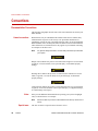
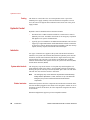
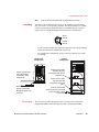
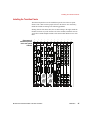
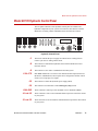
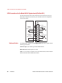
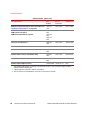
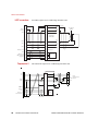
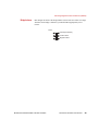
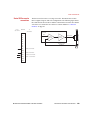
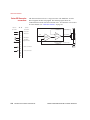
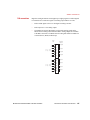
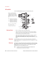
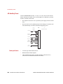
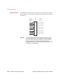
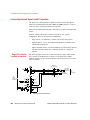
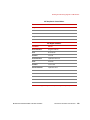
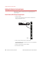
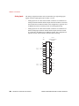
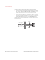
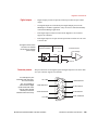
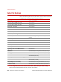
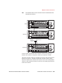
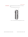
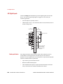
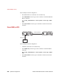
Connector J43 Interlock accommodates two general purpose inputs to be
connected to the interlock chain.
•
Input 1 is dedicated as a station interlock.
•
Input 2 is dedicated as a program interlock.
•
Both inputs are optically isolated.
•
If just one contact is used, the other must be jumped.
To
Chassis
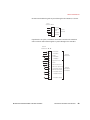
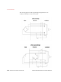
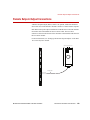
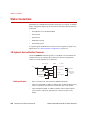
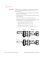
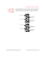
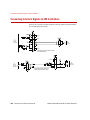
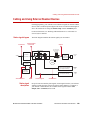
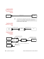
Both inputs can accept relay
contacts or a logic signal.
Both configurations are
shown.
J43
From
External Device
1
+24 V
2
1
Each input can be have Input
Station
Interlock
either configuration.
3
relay
contacts
4
5
+24 V
logic
driver
6
Input 2
Program
Interlock
7
0V
8
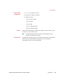
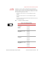
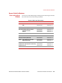
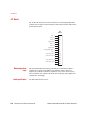
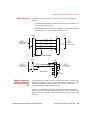
Cable specification
Power characteristics
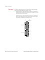
Jumper plug
•
9-contact type D male EMI connector.
•
Backshell–EMI metallized plastic.
•
Cable–shielded twisted pairs (24 AWG minimum) with drain wire(s)
connected to the metallized backshell at the chassis.
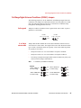
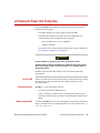
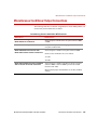
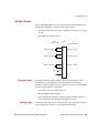
Channel inputs can be 3 volts (minimum) and 26 volts (maximum) from an
external voltage source.
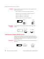
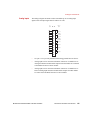
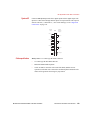
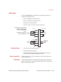
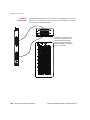
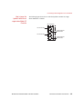
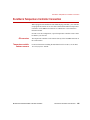
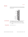
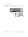
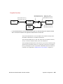
If connector J43 is not used, you must install a jumper plug to maintain the
integrity of the interlocks. Use jumper plug PN 100-007-948 or jumper pins 1
and 2; 3 and 4; 5 and 6; 7 and 8.
Models FlexTest® IIm/GT/SE Controller Hardware
FlexTest GT Controller Connections
137