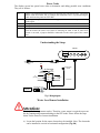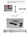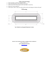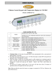
1
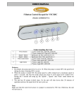
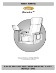
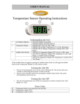
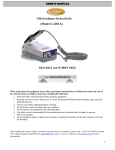
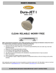
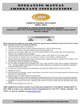
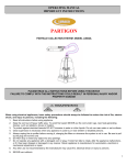
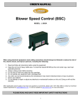
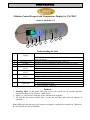
USER’S MANUAL
5-Button Control Keypad with Temperature Display for VSC/BSC
(Model: L1004B-KP-V2)
1
2
3
4
5
6
7
8
9
Understanding the Unit
SCREEN OFF: Unit is in ‘idle’ mode
1
Display
2
3
4
5
8
Temperature in ºF
Jet Mode
Time remaining
All Jets ON
Mode 1
Low Zone
Mode 2
High Zone
Mode 3
Pulse Mode button
9
Light button
6
7
SCREEN ON: Unit is displaying temperature, mode, time remaining or
error information.
When on, the screen displays temperature value in ºF
When on, the screen displays the current active mode 1-3 or pulse
When on, the screen displays the time remaining in minutes
1st press: All Jets ON, LED ON
2nd press: All Jets OFF, LED OFF
1st press: Low Zone and Back Massage Jets ON, LED ON
2nd press: All Jets OFF, LED OFF
1st press: High Zone and Back Massage Jets ON, LED ON
2nd press: All Jets OFF, LED OFF
1st press: Pulse Mode ON, LED ON
2nd press: All Jets OFF, LED OFF
1st press: Light ON, LED ON
2nd press: Light OFF, LED OFF
Features
1. Pulsating Mode: In this mode, each pair of jets will activate for 10 seconds and then
transition to the next set. There are 3 pairs of jets.
2. Mode 1 or “All Jets On” Each pair of jets will turn on in sequence.
3. The unit has 20 minute in-built timer. So the unit will shut down after 20 minutes of
operation.
Note: Make sure that the water level sensor or a jumper is connected to control box. Otherwise,
the unit will not turn on. (If Installed)
Error Codes
The display screen has special error codes to determine and debug possible error conditions.
They are as follows:
E-1
NC
LO
HI
No H20
There is a connection problem between controller box and the keypad. The power
button LED also blinks ‘fast’ to indicate the connection error. Try reconnecting the
cable and reset the power on VSC/BSC.
The temperature probe on the back of keypad is not connected. Try re-connecting
probe again.
Temperature value is Below 50 ºF
Temperature value is Above 140 ºF
The power button LED also blinks ‘slowly’ to indicate this error. The unit will not
turn on because the water level sensor is detecting no water in tub. If water level
sensor is not used, a jumper should be connected at water sensor port of the control
box.
Understanding the Setup
KEYPAD
1
2
3
F
TEMPERATURE SENSOR
(To measure tub water
temp.)
TEMPERATURE
SENSOR CONNECTOR
LIGHT
WATER SENSOR
PROBES
Jet Controller
LIGHT
TRANSFORMER
LIGHT
(1A MAX.)
Pair 3
Jet
(2A Max)
Jet
(2A Max)
Pair 2
Pair 1
RJ-25 CABLE
or
JUMPER
WATER SENSOR
WHITE/NEUTRAL
ELECTRICAL
FEEDER / OUTLET
120V, 20A
BUTTON PORT
BLACK/LINE
GREEN/GROUND
WALL OUTLET
Fig. 1: Wiring diagram
Water Level Sensor Installation
Attention:
The impeller bearing cannot run dry. Therefore, water sensor is required to prevent
the dry running and permanent damage to the JET heads. Please follow the steps
below for the water level sensor installation.
a) Locate the location for the sensor electrodes to be installed. Note: The electrodes
can be installed in vertical or horizontal configuration (Fig. 2b)
b) Drill two holes (3.5mm diameter) on the tub with approximate distance as shown
in Fig. 2b below. Insert the electrodes and tighten the nuts to secure the ring
connectors as shown in Fig. 2a below.
c) Connect the other end of sensor cable to the control box port named “Level
Sensor”
Electrode 1
23in (max)
23in (Max)
Electrode 1
Electrode 2
Electrode 2
Horizontal Configuration
Vertical Configuration
a)
b)
Fig. 2: a) Electrode mounting behind the tub
b) Electrode Configurations
1
2
Fig. 3: Keypad with temperature sensor and RJ25 cable connected
1
RJ25 Cable
2
Temperature Probe
Connect one end to the back of keypad and the other end to the ‘button’
port of control box.
Connect the square female end of the probe to the male end of the
keypad. Drop the probe on water.
Cable Connection Steps
1.
2.
3.
4.
5.
Connect keypad to control box using RJ25 cable.
Connect the temperature probe on the back of keypad.
Connect water level sensor/ jumper on the sensor port of control box.
Connect jets to the control box.
Connect power cable to the power outlet and turn on the unit using power button on keypad.
2D Drawing
Fig. 4: Backside view of keypad (All dimensions in inches)
THANK YOU FOR BUYING LURACO TECHNOLOGIES’ PRODUCTS
LURACO TECHNOLOGIES, INC.
1132 107TH STREET, ARLINGTON, TX 76011
TEL: +1-817-633-1080, FAX: +1-817-633-1085
WWW.LURACO.COM