1
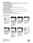
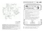
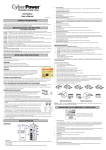
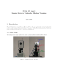
CONSIDERATION FOR THE INSTALATION From the thermal point of view it is useful to know that the device especially if used in high ambient temperatures at full load can exceed 80 ° C, for this reason it is strongly recommended to keep it away from any objects that are affected by high temperatures. To facilitate heat dissipation is strongly recommended to install the device with the fins upright. It is advised to leave at least 15cm of space above the device. Electrically it is important to remember that, due to the possibility of high current loads, the voltage drop on the cables are not negligible. It is important to install the device as close as possible to the devices powered from it. In this way it minimizes the distance to the load, (13.5V), and consequently minimize the voltage drop. B E VR60SW 3 GENERAL CHARACTERISTICS The design utilises a poly-phase switching voltage reducer topology , a feature that minimises both radiated and conducted noise. The energy balance and efficiency between input and output is greater than 96% The device is protected against: Reverse polarity Over voltage / current input Over voltage / current output Over temperature Specifications: InputVoltage Output Voltage Stand by current Quiescent crrent Maximum Input Current Maximum Output Current Maximum Output Power Ambient temperature 20V a 32V 13.4V ± 0.5V 25mA 400mA ( WARNING Leaving EN Input active may cause undesireable battery discharge) 40A 60A (CONTINUOS OPERATION) 810W –10°C to +55°C www.rmitaly.com [email protected] @ A B 2 USER MANUAL ] 2 Blade Fuses at 30A POWER INPUT The use of excessively rated fuses can cause irreversible damage to the device ^ Connector with screw terminal block _ ` a b [ VR60SW IN FUSE \ Green: OK Yellow: Allarm Red Malfunction 24V EN GND Three-pin plug supplied which can accept cables up to 16 mm ² Positive power cable (+) We suggest to use a cable 16 mm ² YELLOW Negative power cable (-) We suggest to use a cable 16 mm ² BLACK EN signal cable We suggest to use a cable 2mm ² WHITE This signal control the power-up of the device Usually connects to the ignition key circuit however it may alternatively be connected to a remote switch for manual EN signal. Leaving the device permanentaly on could cause an unwanted descharge of the battery d c Safety Fuse ] ] 30A 30A For increased safety it is strongly recommended that an 40A fuse is installed close to the batteryd d Battery or 24V Power source Make sure that the battery is charged, has the correct voltage and is capable of delivering at least 35A [ Input Connector From left to right : 24V input positive (+) power POWER OUTPUT EN input signal for dedicated ignition control device. It is recommended to connect it to the " ignition key output circuit" of the vehicle in which it is installed. In this way, when the vehicle is turned ON, the device and the devices connected to it will turn ON . GND negative input (-) of power ie the reference system ^ \ Status indicator LED _ b 40A FUSE 12/24V - VR60SW OFF the device has no voltage at EN GREEN device is turned on and working normally YELLOW indicates a generic state of alert, this does NOT + + OUT Bi-Color LED. Displays 4 different states: ` a c e affect the output voltage It may be caused by one of the following conditions : Excessive Temperature: In this case the fans will turn on automatically. If the device has been installed in a well ventilated area, this will solve the problem. Excessive Output Current:: Voltage on the output of the converter is less than 12.9V caused from excessive load Low voltage on Input: : voltage on the input of the converter is less than 19.5V. This condithon can reduce the performance of device RED indicates an ALARM for which it was necessary to disconnect the supply voltage to protect the device . This is typically caused by excessive temperature . If the problem is resolved the device automatically resumes operation. FUSE GND 13.5V f f f 30A 30A 30A e Input Connector From left to right: : GND negative input (-) of power ie the reference system 13.5V Pos itive Output Power maximum current 60A f 3 Blade Fuses at 30A g Use of excessively rated fuses can cause irreversible damage to the device g Connector with screw terminal block h i d j 24V 12V LOADS h i Bipolar plug supplied which can accept cables up to 32mm ² Negative power cable (-) We suggest to use a cable 32mm ² BLACK Positive power cable (+) We suggest to use a cable 32 mm ² RED j Devices connected at VR120SW Do not connect loads that absorb in excess of 810W or 60A