1
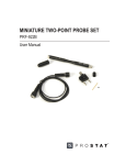
CONTENTS PRESENTATION ................................................................................................3 CONFIGURATION ..............................................................................................4 Overview ......................................................................................................4 Basic interactions...........................................................................................7 Description of the Menu ..................................................................................8 Measurements ............................................................................................8 Historical data ............................................................................................9 Configuration ........................................................................................... 12 Alarms and statuses .................................................................................. 24 Actions .................................................................................................... 25 Information .............................................................................................. 26 TECHNICAL DETAILS ....................................................................................... 28 Technical specifications .............................................................................. 28 Compatibility Protocols .............................................................................. 28 software version ....................................................................................... 28 1 2 PRESENTATION 1 1. Touch screen 2. USB port 3. Ethernet port 3 2 3 CONFIGURATION Overview Sirio Central inverters have a new man-machine interface (MMI) as standard, consisting of a colour LCD Touch panel. The characteristics and the quantity of information enrich the experience of user interaction with the solar inverter. Everything can be done with just a touch. When the inverter is started up for the first time after commissioning, a screen appears asking you choose the country where the inverter is installed: Press the arrows on the right to scroll between the countries currently managed. Once the choice has been made, simply touch the image of the Earth to proceed with the configuration: You can confirm or cancel your choice going back to the previous screen. 4 CAUTION: Choosing the country configures the inverter to the values prescribed by the regulations in force in the country of installation. Once you have made your choice, you cannot change this setting without contacting Technical Assistance Service staff. The interface language can still be changed at a later date using the ADVANCED SETTINGS menu. The next times the device is turned on, after the welcome AROS logo, the screen will appear as shown below (the background color may vary according to the inverter operating conditions): The screen consists of the following main areas: 1. At the top of the screen, the model, date, time and rated power of the inverter are displayed from left to right. 2. The daily graph showing the power delivered is shown in the middle of the screen. The horizontal scale represents the hours (from 5 to 22 i.e. 5 am to 10 pm) while the vertical scale represents the kW. In the top right of the graph is the value of the instantaneous power while on the left is the energy produced during the current day. 3. At the bottom of the screen is a line providing status information, with messages that alternate once per second. 4. On the right of the screen, there is a column with buttons that allow you to navigate within the interface. After 5 minutes of inactivity, the LCD screen enters screensaver mode. Just tap it to return to normal viewing. The following symbols may appear on the off screen during daytime: The first symbol indicates that inverter operation is regular, the second that solar radiation is low and the third indicates an alarm. 5 The buttons on the right-hand side of the column let the user access the main functions; they have the following symbols and meanings: Inverter measurements Page 8 Data log Page 9 System configuration Page 12 Inverter statuses and alarms Page 26 Inverter actions Page 25 Information Page 26 Note that, on the main screen, touching the graph area of the screen displays the energy produced monthly: Swiping the finger on the screen from left to right or from right to left it’s possible to see data of previous/next month. Touching it again will display the annual graph: 6 Swiping the finger on the screen from left to right or from right to left it’s possible to see data of previous/next year Touching it again returns you to the home page. Basic interactions All the features and customizations of the system can be queried using the following actions: Touch: touching the button or specific area of the screen; Swipe: moving your finger on the screen while holding it down, from right to left or from left to right. This may be required to navigate through the daily graphs or between different screens on some occasions. Whenever a touch or swipe is recognized, the MMI will confirm with a beep. For file transfer, a USB flash drive with a single FAT32 partition is required; otherwise it will be impossible to complete the data saving operation correctly. 7 Description of the Menu MEASUREMENTS From the main window, as seen, you can access the other areas of the interface. In particular, press the button to consult the inverter measurements: The synoptic panel shows all the main device measurements. The three buttons on the right-hand side allow you to view the temperatures measured inside the inverter and the measurements of the four analogue probes if connected, and to return to the main window (button also in the lower level masks). 8 HISTORICAL DATA The button allows you to access the screens for managing the historical inverter data: To view the logs, press the button with the symbol. Then select the measurements to be displayed (only two series can be displayed at the same time): To select a measurement, press the corresponding button. A white tick will appear on a green background to highlight the choice. If you want to deselect an item, simply press the button again. To proceed with reading of graphs, press 9 Now you can: Go ahead and back one day with a simple touch: scrolling across the screen from right to left and from left to right respectively Go ahead one year Go ahead one month Go back one month Go back one year Send the graph by e-mail (the button only appears if the service is configured). The units of measurement appear at the bottom. The horizontal axis is always temporal in the time range [5 - 22]. The vertical axis on the left has the left-hand unit of measurement and the one on the right has the right-hand unit of measurement. The curves always have different colours. To save the historical data on a USB flash drive, press the button with the following window appears: symbol. The As already mentioned, the USB flash drive must be FAT32 (VFAT) formatted and have a single partition. Many USB flash drives that have dedicated protection software with special partitioning schemes may not work. 10 After inserting the USB flash drive, wait a few seconds and press the button with the symbol to allow the system to recognize the memory (recognition is not automatic). If the operation succeeds, the following message will appear: Otherwise: Press again to copy. When finished, press the button with the drive. symbol in order to safely remove the USB flash Note that over time, the historical data takes up the device memory. The manage the archives, eliminating annual data no longer of interest: button allows you to To select the year, drag your finger from right to left or from left to right. When is pressed, the year will be highlighted in red. Touch the screen to confirm deletion. Please note that data deletion cannot be reversed. In order to download the system log from the control panel (useful if required by Technical Assistance in order to diagnose any problems), press the button with the 11 symbol. From the screen that follows follow the instructions to start downloading the system card logs. To cancel the operation, go back to the previous screen. At the end of the download, you can send the logs by e-mail or copy to a USB flash drive. The button allows the user to download the logs of the system board and of the display on USB key. Use the same procedure seen before. CONFIGURATION From the main screen, press to access parameter configuration: 12 Once again, on the right, there are additional buttons which, from the top downwards, can be used to set user parameters, system parameters (do not require a password but an in-depth knowledge of network issues) and to access terminal mode for low-level interaction with the inverter. The Service section is password-protected. The e-mail configuration section for this page allows you to set the frequency of e-mails for an alarm or event. USER SETTINGS These are activated by pressing : On this screen, you can manually set the €/kWh ratio and reset the partial hour meter for the energy produced. Press on the other hand to access screen brightness configuration and enable/disable the buzzer. If enabled, the buzzer will sound an alarm that disappears when the alarm stops. The alarm sound changes if an operator interacts with the interface. After 20 minutes of inactivity, if an alarm is still active, the sound will go back to the initial one. 13 Press to set the Date and Time on the inverter: CAUTION: Changing the date and time values during normal operation may cause changes to the graphical display of stored data. Press to set the inverter identifier, needed in order to use the protocols on the 485 serial line and to identify the machine when transferring historical inverter data onto a USB flash drive. If the system has multiple inverters, it is compulsory for the identifiers to be all different from each other. 14 In the same window, we see that for each serial port, it is possible to specify whether the addressing is dynamic or static1; this is a technical issue that regards the compatibility of communication protocols. In particular, this configuration data concerns the PVSER protocol (Proprietary Protocol). Also from here, by pressing you can specify the name of the system in which the inverter is installed or the section of the system: Going back to user settings, using the button, you can configure the four analogue probes (optional - e.g. radiation, temperature, anemometer etc, with electrical output 0-10 V): 1 For more information, consult the SunVision 2 software user manual 15 By pressing one of four buttons, you configure the individual probe: The single measurement, as seen, can be configured in detail: Description Unit of measurement Minimum value (corresponding to 0 VDC input) Maximum value (corresponding to 10 VDC input) The probe can be enabled or disabled as desired. Press the button with the symbol to save the probe configuration. Consult the technical documentation for the 0-10 V probes to enter the correct configuration data. 16 ADVANCED SETTINGS From the configuration screen, press language: Press for the network settings and to choose the interface on the other hand, to go to the network parameters configuration window: The IP address may be assigned statically, as in the previous figure, or can be obtained through a DHCP server. Touch the selection box to choose this setting: Press the button with the symbol once you have chosen the desired network configuration. When the IP addresses are entered, the software automatically performs a check, displaying the and symbols next to each edited address, showing whether the addresses have been entered correctly or not. Let’s look at the other options. 17 UDP: the port value set is that used for communication in UDP on the Ethernet network (e.g. SunVision 2 monitoring software). The value 33000 is the default value. By selecting it and pressing C, you can enter the desired value. SMTP: allows the configuration of the outgoing e-mail server. The following can be configured: 1. SMTP server address and relative port (first screen) 2. Message header fields (From: To: Cc:, second screen) 3. Any username and password for authentication on the SMTP server (optional) It is also possible to send a test e-mail to check that the settings are correct by pressing Then press . to confirm the e-mail configuration. DNS: on this page, enter any DNS server addresses that may be needed for the resolution of the names of the outgoing e-mail server: 18 VNC: with dedicated software (both freeware and paid software are available on the internet), it is possible to connect to the remote display from a personal computer: : You can configure the password (which must be confirmed) and the port used by the service. The default password is “secret”: Press to change the display language. 19 The button makes the user access the configuration page of the external measures that can be used for the auto-consumption function. If the function Extern Modbus Measure is selected, a set of default parameters are presented. These parameters are prepared for the external instrument given by Aros Solar. Anyway it’s possible to connect other brand instruments on the 485 bus; in this case an accurate reading of the manual is suggested to have the correct settings : Use the and buttons to change the set of parameters. Select the High checkbox to change the upper part of the register. If the set of parameters are correct, the measure will appear in the upper right side of the screen. Now the button can be used to accept the parameters. If the Power Reduction checkbox is selected and hitting the configured as a master of a set or group of other inverters. 20 button again, the inverter will be In this case we can scan the LAN to find the other inverters : In order to scan the LAN, press the Press the button button ; this will lead the user to the screen : to execute a scan of the LAN. All the inverters must have the same label plant name to be found. See the self-consumption documentation for details. 21 TERMINAL MODE From the Configuration screen, press to access Terminal Mode where you can set the inverter with the various operating modes and the various parameters requested for the standards in the place of installation. In order to configure the device correctly, refer to the manual accompanying the inverter. SERVICE In the configuration window, the button is reserved for AROS Solar Technology Technical Assistance personnel. These functions are password protected. It’s also possible to calibrate the touch panel. Hit the calibration: Pressing button to request a touch panel will start the calibration. Follow on-screen instructions. 22 E-MAIL CONFIGURATION From the settings window, it is also possible to configure the behaviour of automatic e-mail sending. Access the configuration by pressing . If the procedure described in the ADVANCED SETTINGS section, SMTP paragraph, has not been completed successfully, it will not be possible to configure its behaviour. In the event that the procedure is successful, the following will be displayed: Press or to enable or disable sending of a type of e-mail and press increase or decrease the delay time, in minutes, before sending an individual e-mail. to For example, if you want an e-mail to be sent 5 minutes after switching the device on, the configuration should be as follows: We recommend that you enter a waiting time of at least 10 minutes to prevent email from being sent during typical morning and evening switch-on attempts. 23 ALARMS AND STATUSES Press to enter the screen showing the inverter alarms and statuses: You can use your finger to scroll through the list of any alarms. Remember that in the event of an alarm, a sound will be emitted at 5-second intervals until the alarm disappears or the user touches the screen. If the user touches the screen, the sound will change intensity and timbre. If after 20 minutes the user has not deleted the alarm, the sound will go back to the original one. The alarm sound can be enabled or disabled in the CONFIGURATION section in the User settings paragraph. 24 ACTIONS Press to enter the section where you can perform actions on the inverter: The first button allows you to disable the inverter and re-enable it. The second button allows you to restart the graphical interface for any display software updates. This action does not affect inverter operation in any way. The button , if pressed, disables the UDP slave function in the self-consumption case. To enable the function again, hit the same button, that in the meanwhile has changed its appearance, 25 INFORMATION Press to enter the Information section. This contains all the information regarding the inverter: The total energy produced by the inverter The total hours of operation The operating mode The identifier The maximum temperatures reached by the system (internal machine temperature) and the inverter (probes on power module heat sinks) Presence of the built-in isolation transformer The installation date (Year-Month-Day) The Euros saved The energy hour meter used (can be reset by the user) The maximum power reached In addition to the above information, you can also display the current software version, the control panel firmware versions, the IP address of the network interface, the amount of free memory and the occupation of the flash drive: 26 By touching the screen, you can access more information about the status of communications: In this example, we see a PVSER/UDP connection on the Ethernet port and and an external measure on slot 1. The green/red blinking led means that on that slot is present receiving data. The grey led means no incoming data on the specific slot. 27 TECHNICAL DETAILS TECHNICAL SPECIFICATIONS LCD resistive touch screen, TFT, 480x272 One Ethernet port One slot for a USB memory, FAT32 COMPATIBILITY PROTOCOLS PVSER2; static and dynamic addressing PVSER/UDP2 (default port: 33000, configurable) MODBUS MODBUS/TCP RFB protocol (used by screen sharing programs, such as VNC), protected by (configurable) password. The default password is secret. Sunvision 2 (from 2.0.5 version upwards) could ask for a user/password to recover historical data. In this case the user is ftpuser and the password is arosftp. SOFTWARE VERSION 2 This manual refers to the 1.2.1 version of the touch screen software. Proprietary protocol 28 29 0MNPHV12K55ENUA‐01