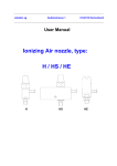
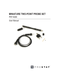
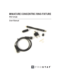
1
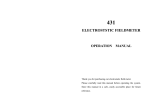
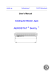
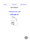
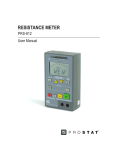
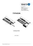
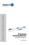
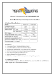
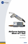
static decay timer
pdt-740b
User Manual
Table of Contents
PROSTAT® pdt-740b static decay timer
Section
Topic
Page
I.
Introduction
4
II.
Before using the PDT-740B
4
III.
Safety
4
IV.
Function
5
V
Measurement Response Time
5
VI.
Battery Installation & Maintenance
5
VII.
Connecting the PDT-740B to PFM-711A Fieldmeter
6
VIII.
Normal Operation for Ionization Static Decay Measurements
7
IX.
Suggestion “A” for Material Static Decay Measurements
9
General Specifications
13
© 2011 by Prostat® Corporation. All rights reserved. Printed in the United States of America. No part of this manual may
be used or reproduced in any manner whatsoever without written permission. For information contact
Prostat Corporation, 1072 Tower Lane, Bensenville, IL 60106 USA
Prostat is the registered trademark of Prostat® Corporation
PDT-740B Static Decay Timer
NOTE
Before using this, or any other electronic piece of equipment,
carefully read the instruction manual completely.
I. Introduction
The PDT-740B Static Decay Timer is typical of Prostat’s innovative technology and support of Professional
ESD Control Managers and Auditors. This unique accessory is designed to measure the decay time of
ionizers from ±1,000 volts to less than 100 volts in accordance with ESD Association’s Ionization Standard
ANSI/ESD STM3.1, and measure material decay time to less than 50 volts and less than 10 volts. Properly
used, the PDT-740B provides decay time measurements for evaluating ionizers, packaging materials, footwear, personnel grounding, production aids, some equipment and many other ESD control products.
The PDT-740B Static Decay Timer is used with Prostat’s precision portable Charge Plate Monitor kit components, including the PFM-711A Field Meter, CPM-720A Charge Plate Assembly and PCS-730 ±1kV Charging Source. For evaluating materials and other products, additional decay measurement accessories e.g.,
PGB-745 Decay Electrode, or PRF-911 Concentric Ring fixtures are recommended.
II. Before using the PDT-740B Static Decay Timer
A. Examine the instrument for damage, contamination (excessive dirt, grease, etc..) and defects. If
any abnormal conditions exist, do not attempt to make any measurements.
B. Basic contents of the PDT-740B package include:
1. PDT-740B Instrument
2. One 9 volt battery
3. 40 inch (tip to tip) analog cable equipped with two (2) mini-phono jacks.
4. Certificate of Calibration
5. Available options include:
a. Prostat PGB-745 Static Decay Electrodes
b. PRF-911 Concentric Ring Fixture and PTB-920 Dual Test Bed
c. PTB-915 3x5.5 inch insulated test bed and 3x6 inch stainless steel test bed
III. Safety
The following safety information must be observed to insure maximum personal safety during the operation of this meter.
A. DO NOT use the instrument if it appears damaged, or if you suspect it is not operating properly.
B. Measuring voltages which exceed the limits of this instrument, i.e., greater than 1,500 electrostatic
volts, may damage it and expose the operator to a shock hazard. Always observe instrument voltage limits as stated.
4
Rev. B / February 2005
PDT-740B Static Decay Timer
C. As with other electronic devices, do not use or operate in wet conditions or in hazardous combustible environments.
IV. Function
The PDT-740B is designed specifically to measure decay time of ionizers and materials in seconds and
tenths of a second from 1,000 to 100, 50 or 10 volts. It is used with the Prostat PFM-711A Field Meter
and CPM-720 Charge Plate Monitor Assembly, or an equivalent instrument having an analog output of 1
volt equaling 10,000 electrostatic volts. This easy to use instrument comes equipped with LCD display, an
analog input for connection to the field meter, ON/OFF Power Switch and a VOLTAGE CUT-OFF SELECTOR
(10, 50 or 100 volts) switch.
V. Measurement Response Time
The PDT-740B response is 0.2 seconds at 100 volt CUT-OFF and 0.3 seconds at 50 and 10 volt CUT-OFF.
VI. Battery Installation & Maintenance
A. Battery Replacement
1. Power is supplied by a 9 volt “transistor” battery that will provide greater than 40 hours of
operation without replacement.
2. Replace the battery periodically or when the GREEN RESET indicator will not reset in normal
operations.
NOTE: Dead battery voltage is approximately 7.2 to 7.5 volts.
3. Unit should be OFF when replacing battery.
4. To replace the battery:
a. Remove the cover from the back of the instrument.
b. Remove the battery from the case.
c. Connect a new battery to terminals and insert it into the battery compartment.
d. Replace the battery cover by sliding it carefully in the grooves provided. Do not over force
the cover on.
Rev. B / February 2005
5
PDT-740B Static Decay Timer
If the cover does not re-install easily, remove the battery and reinsert for a better fit. Be
sure wires do not hamper closing the battery cover.
e. The PDT-740B is now ready for use.
B. Storage & Cleaning
1. The unit should be stored in clean, dirt free conditions at normal room temperature and humidity. The ideal storage environment is within a Prostat designed case or kit.
2. Simply maintain the outer surface and display by wiping with a non-abrasive low linting cloth.
GREEN LED
READY LIGHT
RED LED TIMING
IN PROGRESS
ANALOG INPUT
JACK
ON/OFF SWITCH
CUT-OFF VOLTAGE
SELECTOR SWITCH
VII.Connecting the PDT-740B to PFM-711A Fieldmeter
A. Mount the CPM-720 Charge Plate Assembly onto the PFM-711A in accordance with their manual
instructions.
B. With both instruments’ power switch OFF, connect the analog cable between the PFM-711A Field
Meter and PDT-740B Static Decay Timer:
1. Insert one cable mini-phono plug into the PFM-711A Analog Output receptacle located on the
left front panel of the instrument.
2. Insert the opposite end of the cable into the PDT-740B Analog Input receptacle located on the
left front panel of the instrument.
6
Rev. B / February 2005
PDT-740B Static Decay Timer
C. Slide the PFM-711A power switch to kV/inch to energize the field meter
D. Slide the PDT-740B ON/OFF switch to ON.
E. The system is ready for use
VIII.
Normal Operation for Ionization Static Decay Measurements
Overview:
The dual phono plug cable assembly is connected to the analog output of the PFM-711A Field Meter and
the Analog Input of the PDT-740B Decay Timer. With the Charge Plate Assembly (CPM) installed on the
Field Meter, the Charging Source is used to apply greater than ±1,000 volts to the CPM. To measure an
ionizers decay time performance, proceed as follows:
A. While wearing a properly grounded wrist strap, grasp the PFM-711A/CPM-720 assembly in one
hand making sure your hand contacts the grounding snap on the back of the PFM-711A Field Meter.
1. Place the PFM-711A Field Meter power switch in the kV/inch position and ZERO the instrument.
2. Note: Your hand should not make contact with, nor obstruct the CPM-720 Charge Plate Assembly in any way.
Rev. B / February 2005
7
PDT-740B Static Decay Timer
B. Turn ON PDT-740B Timer and select 100 Cut Off Voltage
1. With Charging Source properly grounded and held in your other hand, charge the CPM-720
Plate using the PCS-730 ±1KV Charging Source to > ±1,000 volts. When voltage exceeds ±1,000
volts, the PDT-740B Static Decay Timer automatically:
2. Resets its display to ZERO (00.0)
3. Turns ON its Green LED, which provides Decay Cycle
Ready indication.
C. Assuming you are auditing a desk top blower, position
the CPM-720 Charge Plate in the ionizers air flow approximately 12 inches from air output grid
D. As the ionizer neutralizes CPM voltage, the field meter
voltage will drop below ±1,000 volts, at which time:
1. The Green LED Decay Cycle Ready automatically goes OFF
2. The PDT-740B LCD display begins timing function in seconds
3. The PDT-740B Red LED Timing in Progress automatically comes ON and stays ON until voltage
decays to 100 (±2) volts
4. When CPM plate voltage reaches 100 volts or less, the timer stops and the Red Timing in Progress LED goes OFF.
8
Rev. B / February 2005
PDT-740B Static Decay Timer
E. Repeat the above procedure for additional measurements.
IX. Suggestion “A” for Material Static Decay Measurements
Overview:
The dual phono plug (input) cable assembly is connected to the analog output of the PFM-711A Field Meter and the Analog Input of the PDT-740B Decay Timer. The Charge Plate Assembly (CPM-720) is installed
on the Field Meter. One end of a high resistance lead is connected to the CPM-720 Plate and the other
end connected to a Prostat PGB-745 Electrode. The PCS-730 Charging Source is used to apply greater
than ±1,000 volts to the CPM, which is shared with the PGB-745 Electrode. To measure material’s decay
time performance, refer to the figures below and proceed as described.
Rev. B / February 2005
9
PDT-740B Static Decay Timer
A. Setup PFM-711A Field Meter, PCS-720 Charge Plate and PDT-740B Static Decay Timer as described
and illustrated above.
B. Place the material to be tested on a grounded steel test bed.
C. Connect the PGB-745 Static Decay Electrode to the CPM-720 Charge Plate using a high resistance
lead, and suspend the electrode above the specimen to be tested.
D. While wearing a properly grounded wrist strap and the PFM-711A/CPM-720 is connected to
ground:
1. Place the PFM-711A Field Meter power switch in the kV/inch position and ZERO the instrument.
2. Note that the PFM-711A Field Meter and CPM-720 Charge Plate Assembly may lay on a
grounded conductive worksurface or be attached to ground through the PFM-711A ground
snap. Nothing should be in contact with the upper CPM-720 plate except the high resistance
lead.
E. Turn ON PDT-740B Timer and select Cut Off Voltage
F. With Charging Source properly grounded, charge the CPM-720 Plate using the PCS-730 ±1KV
Charging Source to > ±1,000 volts. This also charges the PGB-745 Electrode to the same voltage.
When voltage exceeds ±1,000 volts, the PDT-740B Static Decay Timer automatically:
1. Resets its display to ZERO (00.0)
2. Turns ON its Green LED, which provides Decay Cycle Ready indication.
10
Rev. B / February 2005
PDT-740B Static Decay Timer
G. Lower the PGB-745 Electrode onto the specimen under test
H. As the electrode dissipates its charge through or across the test specimen voltage will drop below
±1,000 volts, at which time:
1. The Green LED Decay Cycle Ready automatically goes OFF
2. The PDT-740B LCD display begins timing function in seconds
3. The PDT-740B Red LED Timing in Progress automatically comes ON and stays ON until voltage
decays to set cutoff (±2) volts
4. When CPM plate voltage reaches cutoff volts or less, the timer stops and the Red Timing in
Progress LED goes OFF.
I. Repeat the above procedure for additional measurements.
J. As an option, use two (2) PGB-745 Electrodes as shown below:
Rev. B / February 2005
11
PDT-740B Static Decay Timer
1. Place the specimen to be tested on an insulated test bed
2. Place the second electrode on the test specimen and attached to ground.
3. The first electrode is connected and used as described above.
4. In this case, the charge dissipates from the first electrode, moves across the material to the
second grounded electrode.
12
Rev. B / February 2005
PDT-740B Static Decay Timer
PDT-740B Static Decay Timer Specifications
Controls:
OFF-ON
Cut Off Voltage, 10, 50 and 100 Volts (Selects Voltage to stop timing)
Indicators:
Green LED: Decay Cycle Ready > ±1kV, CPM voltage > ±1,000 volts
Red LED: Timing in Progress, CPM voltage decay timing activated
LOBAT displayed when battery voltage <6.0 volts
Display:
Liquid Crystal Display (LCD) displays elapsed decay time from ±1,000 volts to
selected Cut Off voltage in seconds and tenths of a second (00.0)
Polarity:
Automatically senses Positive & Negative voltage references
Zero & Reset:
Automatically Resets Timer and Display to 00.0 when CPM voltage > ±1kV. Reset indicated when Green LED Decay Cycle Ready LED is ON.
Response:
Approximately 200 milliseconds in combination with CPM and PFM-711A
Timing Range:
From 0.2 to 159.9 seconds
Timing Setpoints:
Reset when voltage input 100mv ±2mv (1,000 Field Meter Volts ±20V)
Cut Off Voltage @ 100 V: 10mv ±0.2mv (100 Field Meter Volts ±2V)
Cut Off Voltage @ 50 V: 5mv ±.2mv (50 Field Meter Volts ±2V)
Cut Off Voltage @ 10 V: 1mv ±0.2mv (10 Field Meter Volts ±2V)
Accuracy:
Typically < ±5%
Power:
One (1) standard 9-volt battery, PROCELL, Eveready #216 (NEDA 1604, JIS 006P, IEC 6F22)Eveready #216
Battery Life:
>40 hours typical
Dimensions:
4.50 inches x 2.75 inches x 1.0 inches
Weight:
6.5 oz. (184 gm)
Rev. B / February 2005
13
PDT-740B Static Decay Timer
NOTES
14
Rev. B / February 2005
Specifications are subject to change without notice.
All Prostat trademarks and trade names are the property of Prostat Corporation.
All other trademarks and trade names are the property of their respective companies.
P R O F E S S I O N A L
S T A T I C
C O N T R O L
P R O D U C T S
Prostat Corporation
Corporate Headquarters • 1072 Tower Lane • Bensenville, IL 60106 • 630-238-8883 • Fax: 630-238-9717 • 1-855-STATIC1 • www.prostatcorp.com