1
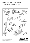
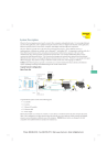
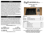
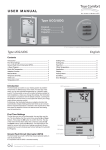
Road Alert Message Sign Controller
User Manual
Table of Contents
Introduction…. ........... …………………….2
Touch Pad Interface.................................2
Operating Instructions ............................3
Powering on the device ...................................3
Display factory default messages ......................4
Display user defined messages .........................4
Selecting a Message for Display ........................4
Clearing Message Display ................................5
Programming User Messages ................5
To Load/Edit Messages via Keyboard Interface ......5
To Load Messages via USB Thumb Drive .............6
Creating Message Effects .......................7
Contact Information.................................8
Part No: 212-0030-USB-D&R
1
Introduction
The ROAD ALERT Controller is a micro-processor controller designed to be used in
conjunction with the RA20 and RA40 Road Alert TM traffic direction devices. The
controller allows for the onboard storage of up to 80 user defined messages in
addition to having five (5) factory loaded messages. Message format allows for a wide variety of message styles to be implemented (i.e. fixed, rolling, scrolling, or flashing)
The controller supports maintenance of user messages using the Road Alert
Message Manager (RAMM) a Windows compatible software interface and loading the message via USB thumb drive (memory stick), or by directly connecting a USB keyboard.
In environments where Road Alert TM devices are single function the keyboard
interface is sufficient. Users wishing to manage a variety of message lists or where the
Road Alert TM devices are shared by departments the RAMM software interface and uploading via a USB memory stick is preferred.
The Touchpad Interface
The touchpad interface allows for complete control of the Road Alert TM device.
Messages may be viewed and selected for display. The touchpad also allows for the addition of user messages via a direct connection to a Windows compatible USB
keyboard or USB memory stick. A complete list of touchpad buttons and functions is shown
in Table 1.
The LED message display area is a two (2) line display, each with a specific
purpose as follows:
1. The top line of the display always displays the message currently displayed on the Road
Alert TM device.
2. The second display line will display messages from the internal or user message list as
appropriate. The message display is the current “active” message.
The ROAD ALERT controller is equipped with two (2) external interface ports (Figure 1.) as
follows:
Figure 1.
Part No: 212-0030-USB-D&R
2
Button
Function
ON/OFF
Turns on the Road Alert TM and touchpad
DIMMER
Reduces the intensity of the Road Alert TM LED display array
SCROLL
Causes the controller to scroll “up” through the user defined
message list
Note: “UP” is defined as from lowest to highest indexed message
SCROLL
Causes the controller to scroll “down” through the user defined message list
Note: “Down” is defined as from highest to lowest indexed message
USB LOAD Function– Activated by holding this key while using the ON/
OFF key.
DISPLAY
Causes the currently “active” message in the LED display area to be displayed on the Road Alert TM device
BACKLIGHT & CONTRAST - Activated by holding this key while using
the ON/OFF key.
ARROW
STORE
In “ARROW” mode allows the user to loop through the factory default message list. Each press of the button will cause the next message in the list to
be displayed as the “active” message in the LED display area
STORE - function is used to complete the loading of the text messages
via the USB thumb drive (stick).
Table 1.
1. USB - allows for direct connection to one of the following;
•
USB keyboard in order to update the user message list (see “Programming User
Messages” section)
•
USB memory stick, to load newly generated messages.
2. LED - This is the communication port to the Road Alert TM Message Sign
Operating Instructions
The ROAD ALERT controller provides all functionality necessary to select and display messages on the Road Alert TM Message Sign.
Note: Ensure the RA20 or RA40 Message Sign has been properly connected to both
power and negative (earth) ground, In addition ensure that the interface cable between the
RA20 or RA40 is connected to the controller before attempting to use.
Powering on the device - Press the ON/OFF button to supply power to both the ROAD
ALERT controller and the Road Alert TM Message Sign. When powered on, the LED message preview display area will display the last message that was displayed on the device
(Continued on page 4)
Part No: 212-0030-USB-D&R
3
Display factory default messages - The following factory default messages are available:
0. Blank (ALL CHARACTERS OFF)
1. Arrow RIGHT
2. Arrow LEFT
3. CENTRE OUT Arrow
4. Flash (alternate flash of two outboard characters)
The default message list is accessed by pressing the “ARROW” button on the touchpad
which will cause the Blank message to appear in the LED message preview display area.
Each subsequent push of the “ARROW” button will cause the next sequential factory default message to be displayed as the “active” message in the LED message preview area.
Display user defined messages - The user defined message list is accessed using the
“SCROLL ” or “SCROLL ” buttons to browse through the messages. Each subsequent
push of the button will cause the next message in that direction to be displayed as the
“active” message in the LED message preview area.
Selecting a Message for Display - At any point the message displayed in the LED message preview area may be displayed on the Road Alert TM Message Sign by pushing the
“DISPLAY” button. When pushed the “active” message in the LED message preview area
will be displayed on the Road Alert TM Message Sign. When a message is being displayed
on the sign the red LED indicator on the “DISPLAY” button will be lit.
Clearing Message Display - The message display may be cleared by displaying the
“Blank” factory default message.
Note: when the “Blank” message is displayed on the device the red LED light on the
“DISPLAY” button is not illuminated.
Programming User Messages
The ROAD ALERT controller has the capacity to store eighty (80) user defined messages.
Messages lists maybe downloaded to the ROAD ALERT controller either by using the
Road Alert TM Message Manager (RAMM) software and a USB thumb drive or directly via
the keyboard interface.
The ROAD ALERT controller (Touch Pad) will already have a set of standard messages
preloaded into the user memory section. If these need to be erased load a USB Thumb
Drive, with a blank message file and follow the loading procedure on page 6. Otherwise
erasing the messages by keyboard will require accessing them one at a time.
To clear messages using the keyboard, press the DEL key when the message is displayed
and confirm YES/NO to message line deletion. Do this for all messages displayed until they
are all gone or just delete what is desired.
To Load/Edit Messages via Keyboard Interface:
1. The controller must be connected to a message device and the device must be
(Continued on page 5)
Part No: 212-0030-USB-D&R
4
connected to power and ground prior to loading messages.
2. Ensure the power to the controller is off (press On/OFF button)
3. To initiate the interface
a. Press and hold the “SCROLL ↓” button (Figure 2).
b. Press and release the “ON/OFF” button. The controller will respond by displaying
the message “D&R Electronics”
c. Release the “SCROLL ↓” button. The controller will respond by displaying the
message “Connect Keyboard or thumb drive” (Figure 3).
d. Connecting the Keyboard will bring up the first line of the already existing message or a blank line (if the messages have been cleared).
4. To enter/edit a message
a. Key the message in using the keyboard. The message will display in the LED
message preview display area as it is typed. NOTE: The cursor will always go
to the beginning of the first message line.
b. If preexisting messages are in memory, the Keyboard “↑” and “↓” arrows
will allow you to scroll though them and the cursor will be at the beginning
of each line. To edit the message just type over the exisiting message.
c. Press ENTER key on the keyboard to initiate the saving if the message, the LED
message preview display area will display the question “Save (Y/N).
d. Enter “Y” on the keyboard to confirm and save message in the controllers onboard memory and advance to the next message line.
e. Enter “N” to return to edit mode, this will also advance the message to the next
one (if you were editing message 1, you will now be at message 2).
Note: The Road Alert TM Message Sign has the ability to display several message
formats (ex. scrolling, rolling, flashing). The format of each
individual message determines how it is displayed by the device. See the section
“Creating Message Effects” for information on how to obtain various effects.
5. Repeat step 4. until all messages have been downloaded or edited to the controller
memory
6. To exit keyboard mode; press the ON/OFF button
(Continued on page 6)
Figure 2.
Part No: 212-0030-USB-D&R
Figure 3.
5
Figure 5.
Figure 4.
To Load Messages via USB thumb drive
Refer to the Road Alert TM Message Manager Programming Manual, to create the
message this is necessary to create the correct message syntax. Not using the
RAMM program to create the text files will result in the files not loading properly into
the Road Alert controller.
1. The controller must be connected to a message device (the RA LED Sign) and
the device must be connected to power and ground prior to loading messages.
2. Ensure the power to the controller is off (press On/OFF button)
3. To initiate the interface;
a. Press and hold the “SCROLL ↓” button (Figure 2).
b. Press and release the “ON/OFF” button. The controller will respond by displaying
the message “D&R Electronics”
c. Release the “SCROLL ↓” button. The controller will respond by displaying the
message “Connect Keyboard or thumb drive” (Figure 3).
d. Connecting the Thumb drive will bring up the first text file on the drive, Using the
“SCROLL ↓” button on the controller will display the text files on the Thumb drive
(Figure 4.) the displayed file will be the one loaded when the store button is
pressed
e. Press the “STORE” button to load and save the message file into the controller
(Figure 5.)
f. Turn OFF the controller and remove the USB thumb drive.
NOTE:
loading a new text file will always overwrite the existing files in the RA Controller
memory location. To erase all messages in the RA controller memory simply create
a blank text file (using the RAMM program) and load it into the RA controller using
this procedure.
To modify a single line or add another message line, use the Keyboard procedure this will
write directly to the onboard memory of the RA controller. Follow the steps outlined in the
keyboard interface portion of this manual.
(Continued on page 7)
Part No: 212-0030-USB-D&R
6
Creating Message Effects
The RA20 (eight character) and RA40 (sixteen character ) devices provide a contiguous
array of LED’s capable of displaying each character in 35 pixel resolution. The microprocessor has built in effects that are triggered based on the configuration of the message.
The user is advised to experiment with different message configurations in order to create
the desired overall effect. The following common effects are detailed and are required
if the message programming is done by USB Keyboard only.
Note: Messages move from right to left on the sign only
1. Fixed Message - to have a message appear continuously on the sign, the message
must be equal to or shorter than the maximum display size (i.e. for the RA20 a message
eight (8) characters or less
2. Scrolling effect - is created by entering a single line message which is greater than the
maximum display size. The message will scroll across the device from right to left
3. Rolling effect - this effect is created by entering a series of message lines separated by
a “line break”. When entering a message via the keyboard interface a “line break” is created by ending each line by pressing the “Page Down” key on the keyboard. Each line
must be less than or equal to the maximum display size for the device.
A maximum of three (3) lines may be entered per message
4. Flashing - This effect is created by entering a rolling message with the same message
line repeated. To vary the flash speed leave a blank message line between repeat lines
Note: Each message line must contain at least one character. To
create a “blank” line press the “SPACE” bar on the keyboard,
followed by the “PAGE DOWN” key
5. Directional arrows - Directional allows may be created in messages by using character
combinations as follows:
a. Left arrow no tail type “<“ (Shift ,)
b. Right arrow no tail; type “>“ (Shirt .)
c. Left arrow short tail type “<-” (Shift , followed by -)
d. Right arrow short tail type “->“ (- followed by Shift .)
Extend the tail by adding additional “-” characters. As an alternate format use the “=“ character as a tail
Part No: 212-0030-USB-D&R
7
D&R ELECTRONICS CO.LTD
8820 GEORGE BOLTON PKWY.
BOLTON, ONTARIO L7E 2Y4
CANADA
TEL: 905-951-9997
FAX: 905-951-0019
Part No: 212-0030-USB-D&R
8