1
Draft (version 1.8)
Navigation Information Systems JSC
ERA GLONASS Terminal
Mandatory Requirements
Moscow, 2010
Table of Contents
1.
PREFACE ............................................................................................................................... 3
2.
ABBREVIATIONS .................................................................................................................... 4
3.
FUNCTIONAL REQUIREMENTS................................................................................................ 6
3.1 DATA TRANSFER MECHANISMS ........................................................................................................ 6
3.2 BASIC REQUIREMENTS .................................................................................................................... 6
3.3 TERMINAL ARCHITECTURE REQUIREMENTS......................................................................................... 6
3.4 TERMINAL MODES OF OPERATION .................................................................................................... 6
3.4.1 Passive mode ...................................................................................................................... 6
3.4.2 Emergency Response mode ................................................................................................ 6
3.4.3 eCall mode .......................................................................................................................... 7
3.4.4 Test mode ........................................................................................................................... 7
3.4.5 Garage mode ....................................................................................................................... 7
3.4.6 OTA firmware download mode........................................................................................... 7
3.5 CURRENT CONSUMPTION REQUIREMENTS ......................................................................................... 7
3.6 BACKUP BATTERY CAPACITY REQUIREMENTS ...................................................................................... 7
3.7 AIR PROTOCOL REQUIREMENTS (DATA TRANSFER BETWEEN THE TERMINAL AND THE BACK END). ................ 7
3.7.1 Content of telematics messages ......................................................................................... 8
3.7.2 List of terminal to back end message transmission reasons .............................................. 8
3.7.3 Content of downlink commands ......................................................................................... 8
3.7.4 Crash profile recording ....................................................................................................... 9
3.8 HARDWARE REQUIREMENTS.......................................................................................................... 10
3.9 FEATURES REQUIREMENTS ............................................................................................................ 10
3.9.1 eCall................................................................................................................................... 10
3.9.2 Handsfree audio ................................................................................................................ 11
3.9.3 Status indication ............................................................................................................... 12
3.9.4 Internal integrity monitoring ............................................................................................ 13
3.9.5 Test mode ......................................................................................................................... 13
3.9.6 Accident acceleration profile collection ........................................................................... 14
3.9.7 Automatic crash detection sensor and automatic crash detection sensor test
requirements ................................................................................................................................. 15
3.10 UIM REQUIREMENTS ................................................................................................................... 15
3.11 UNIT CONFIGURATION ................................................................................................................. 15
3.12 TERMINAL CONNECTION ............................................................................................................... 18
4.
STANDARDS COMPLIANCE REQUIREMENTS ......................................................................... 20
4.1
4.2
4.3
4.4
4.5
4.6
4.7
5.
RADIO ELECTRONIC SAFETY ........................................................................................................... 20
RESISTANCE TO EXTERNAL INFLUENCES ........................................................................................... 20
RELIABILITY REQUIREMENTS .......................................................................................................... 21
NAVIGATION PERFORMANCE REQUIREMENTS ................................................................................... 22
ERGONOMIC AND INDUSTRIAL ART REQUIREMENTS ........................................................................... 22
CONSTRUCTIONAL REQUIREMENTS ................................................................................................. 22
SAFETY AND ECOLOGICAL REQUIREMENTS ....................................................................................... 22
PRODUCT PACKAGE REQUIREMENTS ................................................................................... 24
5.1
5.2
5.3
PRODUCT PACKAGE ..................................................................................................................... 24
ADDITIONAL DOCUMENTATION REQUIREMENTS ............................................................................... 24
BRANDING REQUIREMENTS ........................................................................................................... 24
ERA GLONASS Terminal
Navigation Information Systems JSC
Mandatory Requirements
Version 1.8
Page. 2
1. PREFACE
The document defines mandatory requirements for ERA GLONASS terminal units. Functional
requirements defined in Section 3. Standards compliance requirements defined in Section 4. Product
package requirements defined in Section 5.
There are installation configurations discussed in the document:
Aftermarket (retrofit) configuration – terminal installed at service centers or at dealer centers after
vehicle assembled at OEM assembly line
OEM pre installed configuration – terminal installed at OEM assembly line.
The document defines terminal connection, delivery package and documentation requirements for
aftermarket configuration. Terminal connection, delivery package and documentation requirements for
OEM pre installed configuration to be defined by vehicle OEM.
The document status is working draft. The document can be changed without prior notice.
ERA GLONASS Terminal
Navigation Information Systems JSC
Mandatory Requirements
Version 1.8
Page. 3
2. ABBREVIATIONS
Abbreviation
Description
3D
Three Dimensions
ADC
Analogue to Digital Converter
AEC
Acoustic Echo Cancellation
AGC
Automatic Gain Control
ASR
Automatic Speech Recognition
CLI
Caller Line Indication
CLID
Caller ID
CPU
Central Processing Unit
DOP
Dilution of Precision
DTC
Diagnostics Trouble Code
eCall
Emergency Call
ERA
Emergency Road Assistance
ETSI
European Telecommunications Standards Institute
GPRS
General Packet Radio Service
GPS
Global Positioning System
GLONASS
GLObal NAvigation Satellite System
GSM
Global System for Mobile communications
HF
Hands Free
HMI
Human Machine Interface
HW
Hardware
IMEI
International Mobile Equipment Identity
IO
Input Output
IP
Internet Protocol
IVS
In Vehicle System
LED
Light Emission Diode
ERA GLONASS Terminal
Navigation Information Systems JSC
Mandatory Requirements
Version 1.8
Page. 4
MSD
Minimal Set of Data
NAD
Network Access Device
NIS
Navigation Information Systems
OEM
Original Equipment Manufacturer
OTA
Over The Air
PSAP
Public Safety Answering Point
RAM
Random Access Memory
RTC
Real Time Clock
SIM
Subscriber Identity Module
SMS
Short Message System
SOS
Save Our Spirits
SRS
Supplemental Restraint System
SUV
Sport Utility Vehicle
SW
Software
TBD
To Be Determined
TBH
Total Harmonic Distortion
TCU
Telematics Communications Unit
TS
Technical Specification
UI
User Interface
UIM
User Interface Module
VDA
Verband der Automobilindustrie (in German)
VIN
Vehicle Identification Number
ERA GLONASS Terminal
Navigation Information Systems JSC
Mandatory Requirements
Version 1.8
Page. 5
3. FUNCTIONAL REQUIREMENTS
3.1
Data transfer mechanisms
Data transfer between the terminal and the back end should utilize GSM cellular networks. Data transfer
mechanisms include in-band modem, SMS, and GPRS. In-band data transmission should be compliant with
European eCall standards.
3.2
Basic requirements
Terminal will provide the following basic functionality: automatic (triggered by crash sensors
provided with the terminal or external sensors which are part of OEM safety system) and manual
(triggered by pushing Emergency Call button) transmission of the minimum set of data with
consequent setup of a voice call to emergency response call center (PSAP).
Terminal should utilize GSM cellular networks for data and voice connection.
Data transfer mechanisms should include in-band modem (for emergency call data transfer). If in-band data
transmission failed, then SMS shall be supported as back-up communication channel to transmit MND.
When emergency call is placed, Service category” element should be set according to event type
(automatic/manual) as described in specification ETSI TS 124 008.
In-band modem should comply to the requirements of specifications ETSI TS 126 267, ETSI TS
126 268, ETSI TS 126 269, ETSI TS 126 969.
Minimum set of data, transmitted by the terminal, should be structured as described in the standard
CEN TS 15722.
Terminal should provide handsfree voice communication to the cabin of the vehicle, with provision
for muting external sound playback devices (such as in-dash radio) during emergency call.
Terminal should provide an indication of its status and mode of operation via light indicator or a
corresponding icon/text message on the in-dash display.
3.3
Terminal architecture requirements
Main terminal module should provide functionality required for emergency assistance services.
3.4
Terminal modes of operation
3.4.1
Passive mode
Passive mode is intended for transportation and repairing/installation works. Network registration is
done only in case the ignition is turned on and depends on network registration configuration
setting. No active data transmission is initiated by the terminal. On ignition off all interfaces, GSM
modem, and navigation receiver should be powered down.
3.4.2
Emergency Response mode
Emergency Response mode is intended for rendering emergency assistance services. On ignition on
navigation receiver and automatic crash detection sensor are on, and eCall scenario can be started
on crash detection or Emergency Call button press. Terminal registration scheme in GSM network
defined by configuration settings.
ERA GLONASS Terminal
Navigation Information Systems JSC
Mandatory Requirements
Version 1.8
Page. 6
3.4.3
eCall mode
This is an emergency call mode. Voice connection to the emergency response call-center (PSAP) is
established and MSD is transmitted. In case of unintentional call interruption the terminal will reestablish the call. Navigation receiver and all interfaces are powered on.
3.4.4
Test mode
Test mode is intended for testing the functionality of the IVS. The operation is identical to eCall
mode, but voice calls are forwarded to a dedicated call center, and the mode identifier field in
emergency data set is set to “test”.
Provision should be made for automatic termination of testing mode when the vehicle moves with
ignition on to the distance greater than predefined distance (configurable parameter) from the
position where the testing mode was turned on.
3.4.5
Garage mode
Garage mode is intended for disabling terminal functional temporarily for the period of car service at
a service station.
Provision should be made for automatic termination of garage mode when the vehicle moves with
ignition on to the distance greater than predefined distance (configurable parameter) from the
position where the garage mode was turned on.
3.4.6
OTA firmware download mode
OTA firmware download mode is intended for firmware upgrade over the air (via GPRS). In case the
external power is present, the terminal is registered in GSM network, GPRS session and IP
connection to the back end are established. Other aspects of operation are determined by the mode
which was active prior to firmware loading mode.
Once firmware loading is complete, the terminal should restart and return to the mode which was
active prior to firmware loading mode.
Firmware loading mode can be entered from any state, except for garage mode and Emergency Call
mode. If garage mode or Emergency Call mode entered, the firmware loading mode shall be
interrupted.
3.5
Current consumption requirements
Current consumption at 12 V (in absence of GSM transmission) should not exceed the following
values:
3.6
Standby mode (automatic crash detection sensor on, GLONASS/GPS receiver off, terminal
registered in GSM network, but GPRS session not established) – 10 мА
Deep sleep mode (automatic crash detection sensor, GLONASS/GPS receiver and GSM
modem are off) – 1 мА.
Backup battery capacity requirements
Backup battery shall provide 1h voice call plus 8h standby mode operation at 20:C after 24h
charging.
3.7
Air protocol requirements (data transfer between the terminal and the
ERA GLONASS Terminal
Navigation Information Systems JSC
Mandatory Requirements
Version 1.8
Page. 7
back end)
Data transfer should allow for the following groups of functions:
1. Telematics messages transfer from the terminal to the back end.
2. Commands transfer from the back end to the terminal (e.g. test mode on).
3. Transfer of configuration parameters from the back end to the terminal and from the
terminal to the back end
4. OTA firmware download.
3.7.1
Content of telematics messages
Telematics messages from the terminal to the back end should contain the following data:
Message serial number
Terminal ID number
Mode of operation
External power voltage
Backup battery voltage
Transmission reason
Date and time of the event
Last location date and time
Navigation module status
Real time or last known navigation data (coordinates, speed, heading, number of satellites
used in calculation, DOP parameters)
Accelerometer reading.
3.7.2
List of terminal to back end message transmission reasons
Periodic test message
Reply to request
Backup battery failure
Navigation receiver disconnection or fault
Accelerometer disconnection or fault
Other failures.
Activation of message sending is determined for each transmission reason separately by setting
corresponding configuration parameter.
3.7.3
Content of downlink commands
Commands sent from the back end to the terminal should contain the following data:
Message serial number
Terminal ID number
Authentication code
Command code and parameters
ERA GLONASS Terminal
Navigation Information Systems JSC
Mandatory Requirements
Version 1.8
Page. 8
3.7.4
Crash profile recording
In case that acceleration threshold is exceeded for a predefined time interval, the terminal shall
record acceleration profile before and during the crash. Data array should contain lateral and
transverse acceleration values stored in a cyclic buffer, covering the interval of at least 250 ms with
resolution of at maximum 5 ms (1ms desirable) for the crash, plus 10 s with 100 ms resolution for
the pre-crash history. Crash profile is transmitted as a separate block of data.
ERA GLONASS Terminal
Navigation Information Systems JSC
Mandatory Requirements
Version 1.8
Page. 9
3.8
Hardware requirements
GLONASS or GLONASS/GPS navigation receiver with external antenna
GSM/GPRS receiver
Embedded SIM card
In-band modem for eCall MSD transmission according to eCall standards listed in Section 3.2
Vehicle ignition input
Microphone input, stereo line audio output, stereo amplified audio out
Radio mute output
Optional backup battery to sustain voice operation without external power as required for
emergency service delivery
Automatic crash detection sensor
UIM interface including Emergency Call button (for aftermarket configuration)
Terminal status indicator
Internal RTC with periodical wake-up
Internal Flash and RAM memory
CPU
Power supply
Nominal voltage 12 V and 24 V
Operating temperature range -40 – +85:С.
3.9
3.9.1
Features requirements
eCall
3.9.1.1
eCall call functions shall be available only if eCall call service enabled with ECALL_ON
configuration option.
3.9.1.2
Terminal shall support ECALL_BLACK_LIST. Terminal registration in ECALL_BLACK_LIST networks
shall have the low priority comparing with networks not in ECALL_BLACK_LIST .
3.9.1.3
Emergency Call shall not be initiated if terminal is in network from ECALL_BLACK_LIST.
3.9.1.4
eCall automatic trigger source shall be configurable as one or two of the follows: internal
accelerometer, external crash detection OEM input.
3.9.1.5
eCall shall be triggered automatically when acceleration exceeded CRASH_TRESHOLD (X, Y, Z,
time) value when internal accelerometer used (configurable parameter).
3.9.1.6
eCall shall be triggered automatically per signal from an external crash detection OEM input
when external crash detection OEM input used.
3.9.1.7
eCall shall be triggered automatically when ignition is off and Emergency Call button pressed
within SOS_BUTTON_TIME time (configurable parameter) irrelevant of vehicle ignition line status.
3.9.1.8
ECALL_MODE_PIN should set active in eCall mode.
ERA GLONASS Terminal
Navigation Information Systems JSC
Mandatory Requirements
Version 1.8
Page. 10
3.9.1.9
eCall HF audio processing algorithm shall be compliant with section 3.9.2
3.9.1.10
mode.
eCall audio volume shall be set to maximum. Audio volume control shall be disabled in eCall
3.9.1.11
Microphone mute function shall be not available in eCall mode.
3.9.1.12
eCall functions shall be compliant with eCall standards listed in section 3.2.
3.9.1.13
Bit6 and Bit7 shall be properly set in Service Category information element per TS 24.008.
3.9.1.14
When a call is ‘ringing’ TCU shall maintain the connection for at least ECALL_DIAL_DURATION to
allow the PSAP system to answer the call.
3.9.1.15
The number of dial attempts in automatically triggered eCall shall be configurable as
ECALL_AUTO_DIAL_ATTEMPTS. ECALL_AUTO_DIAL_ATTEMPTS set to 0 means the system dials until
successfully connected.
3.9.1.16
The number of dial attempts in manually triggered eCall shall be configurable as
ECALL_MANUAL_DIAL_ATTEMPTS. ECALL_MANUAL_DIAL_ATTEMPTS set to 0 means the system dials until
successfully connected.
3.9.1.17
If eCall triggered automatically, PSAP connection not yet established and
ECALL_AUTO_CAN_CANCEL configuration parameter set to TRUE, then eCall shall be cancelled if Service
button pressed.
3.9.1.18
If eCall triggered manually, PSAP connection not yet established and
ECALL_MANUAL_CAN_CANCEL configuration parameter set to TRUE, then eCall shall be cancelled if Service
button pressed.
3.9.1.19
eCall shall be triggered with the defined activation flag if SMS in a special format arrived from
back end.
3.9.1.20
If eCall happened, then terminal shall send additional telematics message to back end with
eCall parameters if end user subscribed to Alarm, SVT or fleet management services.
3.9.1.21
If SMS with special format received from back end, then terminal shall send SMS with MND to
configurable phone number ECALL_SMS_FALLBACK_NUMBER.
3.9.2
Handsfree audio
3.9.2.1
With vehicle specific tuning HF algorithm shall be VDA compliant and shall achieve Type I fullduplex operation under normal operating conditions in SUV vehicle on concrete surface at all volume
levels.
3.9.2.2
HF algorithm shall provide programmable and fully automatic noise reduction up to 21 dB (1520 dB typical).
3.9.2.3
HF algorithm shall accept common configuration parameter set providing leading market
performance for full duplex communication pro install system.
3.9.2.4
The same parameter set should be used for 1 speaker configuration and for 2 speaker’s
configuration.
3.9.2.5
HF algorithm shall support vendor specific configuration parameter set for fine tuning for
ERA GLONASS Terminal
Navigation Information Systems JSC
Mandatory Requirements
Version 1.8
Page. 11
specific vehicle platforms.
3.9.2.6
HF algorithm shall have vendor specific tuning interface.
3.9.2.7
HF algorithm shall support 1 microphone configuration.
3.9.2.8
If 2 microphone configuration used, then delta of NR shall be >6 dB without speech quality
impact so acceptable for ASR.
3.9.2.9
AEC by the adaptive filter shall be >= 40 dB.
3.9.2.10
Overall echo cancellation (AEC + NLP) shall be >= 55 dB.
3.9.2.11
Echo tail length shall be >= 32ms.
3.9.2.12
HF algorithm convergence time shall be <= 1 second.
3.9.2.13
Attenuation in dB inserted by NLP during single talk shall be <15 dB on uplink and 0 dB on
downlink.
3.9.2.14
Switching time needed to remove attenuation by NLP shall be <50ms.
3.9.2.15
Attenuation in dB inserted by NLP during double talk shall be <= 3 dB on uplink and <= 3 dB on
downlink.
3.9.2.16
Overall echo loss provided during double talk shall be >36 dB.
3.9.2.17
The acceptance level of non-linear distortions (TBH) in the echo path shall be 10%.
3.9.2.18
HF algorithm shall have a configurable equalizer to tune AC frequency response.
3.9.2.19
HF algorithm shall provide Automatic Gain Control (AGC).
3.9.2.20
HF algorithm shall provide noise-dependent volume control.
3.9.2.21
Optionally - HF algorithm shall provide mixing of signals from several audio sources (e.g.to
remove navigation prompts from uplink audio).
3.9.2.22
HF algorithm shall provide a feedback eliminator (shall prevent howling).
3.9.2.23
HF algorithm shall provide a Shock eliminator in line with AS/ACIF S004:2004 standard and ACIF
G616:2004 recommendation
3.9.3
Status indication
3.9.3.1
Below ECU operating modes should be indicated with ECU status indicator:
system ready
system failure
eCall active
test mode
ERA GLONASS Terminal
Navigation Information Systems JSC
Mandatory Requirements
Version 1.8
Page. 12
3.9.4
garage mode.
Internal integrity monitoring
3.9.4.1
Terminal shall perform internal integrity monitoring and transmit status messages every
SELFTEST_INTERVAL and in case of failure detection.
3.9.4.2
This shall be possible to initiate internal integrity check from back end and from wired
diagnostics interface.
3.9.4.3
Terminal shall set Diagnostics Trouble Code (DTC) in the internal memory if a failure detected.
3.9.4.4
Terminal DTC codes shall be restored after ignition off / ignition in cycle.
3.9.4.5
Terminal DTC codes shall be readable from back end and trough wired diagnostics interface.
3.9.4.6
Terminal DTC codes shall be clearable from back end and trough wired diagnostics interface.
3.9.4.7
Below integrity checks shall be performed if technically possible. Corresponding DTC’s shall be
set if a failure detected
Main SW image integrity
Additional SW images integrity (if additional SW images present)
GSM modem HW interface
GLONASS/GPS receiver
Backup battery voltage level OK
Automatic crash detection sensor
Internal RTC
UIM works OK (aftermarket configuration)
Microphone works OK.
3.9.5
Test mode
3.9.5.1
This shall be possible to turn test mode on and off from back end, from wired diagnostics
interface or per user input.
3.9.5.2
User shall be able to turn test mode on and off using UIM w/o additional equipment.
3.9.5.3
One test session shall supported at given point of time so if a test session started from back
end, then subsequent request to start test session from a wired diagnostics shall be discarded and error
reported.
3.9.5.4
System in the test mode shall execute system test commands issued from back end or from
wired diagnostics interface.
3.9.5.5
Each test command shall run until completed. If a test command is running and a new test
command arrived, then the new test command shall be discarded and an interface error shall be reported.
ERA GLONASS Terminal
Navigation Information Systems JSC
Mandatory Requirements
Version 1.8
Page. 13
3.9.5.6
Watchdog timer shall be set in the test mode for TEST_MODE_WATCHDOG time.
3.9.5.7
System shall reset if the watchdog timer expired, but currently running test command not
ended. Test mode should be still on after the system reset, but hanging test command shall not be
restarted.
3.9.5.8
System reset event in the test mode shall be reported to back end or through wired diagnostics
interface.
3.9.5.9
mode.
Test mode shall be ended by special command. System shall reset and enter normal operating
3.9.5.10
Test mode shall end automatically if the vehicle moves for more than TEST_END_DISTANCE
from the location when the test mode was started.
3.9.5.11
This shall be possible to run tests listed in section 3.9.4.7 in the test mode.
3.9.5.12
Visual indication in the test mode shall include the following: no GSM coverage; GSM coverage
OK, but cannot setup GPRS connection; no GLONASS/GPS signals; accelerometer problem; other problems.
3.9.5.13
Test sequence in the test mode shall be defined by back end. Test results saved at back end.
3.9.5.14
Additional tests shall be implemented in the test mode:
eCall to test server using ECALL_TEST_NUMBER with “test call” flag set triggered by Emergency Call
button press
Microphone connection test. For example, ask the user to say predefined phrase and recognize the
speech with ASR.
Speaker (speakers) connection test. For example: play tone or voice prompt to Left / Right speakers
and ask the tester to confirm the tone or voice prompt sounded OK in Left / Right speakers
Ignition off / ignition on test
Extended UIM test. For example, play voice prompts asking the tester to press specific buttons
(button combinations) and check pressed OK. Also may ask the tester to confirm light indicator lit /
blank OK by button press
Backup battery test
Internal accelerometer test.
3.9.6
Accident acceleration profile collection
3.9.6.1
Accident acceleration profile data shall be stored in circular buffer and provide data for
PAYD_CRASH_RECORD_TIME period of time with PAYD_CRASH_RECORD_RESOLUTION resolution after
crash event detected and for PAYD_CRASH_PRE_RECORD_TIME period of time with
PAYD_CRASH_PRE_RECORD_RESOLUTION resolution before crash event detected.
3.9.6.2
Acceleration profile resolution (PAYD_CRASH_RECORD_RESOLUTION) shall be <= 5 ms
(recommended resolution is 1 ms).
3.9.6.3
Acceleration shall be reassured with accuracy 10% and resolution equal or better then:
Lateral acceleration: -5 G to +5 G (resolution 0.1 G)
ERA GLONASS Terminal
Navigation Information Systems JSC
Mandatory Requirements
Version 1.8
Page. 14
Longitudinal acceleration: -24 G to +24 G (resolution 0.1 G in -10 G to +10 G and 0.5 G outside of -10
G to +10 G)
Normal acceleration: -5 G to +5 G (resolution 0.1 G).
3.9.6.4
Accident acceleration profile data shall be automatically transmitted to back end if acceleration
exceeds PAYD_CRASH_ACCEL_TRESHOLD (X, Y, Z, time) configuration parameter.
3.9.6.5
3.9.7
Below data shall be transmitted along with the acceleration profile:
the number of ignition on / ignition off cycles since last crash event
the number of ignition on / ignition off cycles since last transmission of the acceleration profile data.
Automatic crash detection sensor and automatic crash detection sensor test requirements
3.9.7.1
If automatic crash detection sensor not embedded to the terminal unit, then automatic crash
detection sensor shall be supplied with accelerometer mount mechanism which guarantees correct data
collection with acceleration up to 50G and guarantees sensor mounting with acceleration up to 60G.
3.9.7.2
If automatic crash detection sensor embedded to the terminal unit, then terminal unit shall be
supplied with terminal unit mount mechanism which guarantees correct data collection with acceleration
up to 50G and guarantees terminal unit mounting with acceleration up to 60G.
3.9.7.3
Automatic crash detection sensor installation test procedure shall be developed by the terminal
vendor. If necessary, then terminal vendor shall provide mechanism (mechanisms) to be used to test
correct installation.
3.9.7.4
Terminal shall constantly monitor correct automatic crash detection sensor functioning and
report automatic crash detection sensor failure if detected.
3.10 UIM requirements
3.10.1 UIM shall include Emergency Call button.
3.10.2 UIM shall include system status indicator.
3.10.3 Protection mechanism shall be implemented for SOS button to minimize event of wrong
eCall activation.
3.11 Unit configuration
3.11.1.1
Below mandatory unit configuration parameters shall be supported.
Parameter name
Parameter type
Radio mute configuration (for aftermarket configuration only)
RADIO_MUTE_DELAY
INT
RADIO_UNMUTE_DELAY
INT
General configuration settings
ECALL_BLACK_LIST
TBD
AUTOMATIC_REGISTRATION
BOOLEAN
ERA GLONASS Terminal
Navigation Information Systems JSC
Mandatory Requirements
Description
Delay between assertion of the radio
mute signal and the start of audio
playback
Delay between release of the radio
mute signal and the end of audio
playback
The list of networks where eCall
service blocked
Flag which enables automatic SIM
registration in the limited active mode
Version 1.8
Page. 15
SELFTEST_INTERVAL
TEST_END_DISTANCE
INT
INT
ECALL_TEST_NUMBER
STRING
GARAGE_MODE_PIN
ENUM {NONE, PIN_1
.. PIN_8}
TEST_MODE_WATCHDOG
Service level configuration
eCall service configuration parameters
ECALL_SERVICE_ON
CRASH_SIGNAL_INTERNAL
INT
BOOLEAN
BOOLEAN
CRASH_SIGNAL_EXTERNAL
BOOLEAN
SOS_BUTTON_TIME
ECALL_MODE_PIN
INT
ENUM {NONE,
PIN_1 .. PIN_8}
CCFT
INT
INVITATION_SIGNAL_DURATION
INT
SEND_MSG_PERIOD
INT
AL_ACK_PERIOD
INT
MSD_MAX_TRANSMISSION_TIME
INT
NAD_MIN_REGISTRATION_PERIOD
INT
ECALL_DIAL_TIME
ECALL_DIAL_DURATION
NAD_DEREGISTRATION_TIMER
INT
INT
INT
ECALL_AUTO_DIAL_ATTEMPTS
INT
ECALL_MANUAL_DIAL_ATTEMPTS
INT
ECALL_AUTO_CAN_CANCEL
BOOLEAN
ECALL_SMS_FALLBACK_NUMBER
STRING
ECALL_MANUAL_CAN_CANCEL
BOOLEAN
Self-test interval
Distance when test mode and garage
mode should turn off automatically
Phone number to be used for eCall
test calls
Garage mode indication
NONE- no indication
PIN_X – PIN_X active when garage
mode turned on
Test mode watchdog timer
ECALL service enabled or disabled
Internal accelerometer used to detect
crash event
External signal used to detect crash
event
SOS button press detection time
eCall mode indication
NONE- no indication
PIN_X – PIN_X active when eCall
active
Call clear down timer per eCall spec
(should be set to 60 minutes)
INVITATION signal duration per eCall
spec (should be set to 2 seconds)
SEND MSG period per eCall spec
(should be set to 2 seconds)
AL-ACK period per eCall spec (should
be set to 2 seconds)
MSD max transmission time per eCall
spec (should be set to 20 seconds)
Following call clear-down by PSAP
NAD shall remain registered to receive
calls from PSAP (should be set to TBD
value)
Total dial time in eCall initiation phase
Dial duration in eCall initiation phase
De-register from the network after the
timer expired (should be set to 12
hours)
The number of dial attempts in
automatically generated eCall
The number of dial attempts in
manually generated eCall
TRUE – automatically triggered eCall
shall be cancelled if Service button
pressed
If SMS in cpecial format received from
back end, then send SMS with MND to
ECALL_SMS_FALLBACK_NUMBER
TRUE – manually triggered eCall shall
be cancelled if Service button pressed
Acceleration profile collection
ERA GLONASS Terminal
Navigation Information Systems JSC
Mandatory Requirements
Version 1.8
Page. 16
PAYD_CRASH_RECORD_TIME
INT
PAYD_CRASH_RECORD_RESOLUTION
INT
PAYD_CRASH_PRE_RECORD_TIME
INT
PAYD_CRASH_RECORD_RESOLUTION
INT
PAYD_ACCEL_TRESHOL D
ACCEL_CONFIG
Vehicle data
VIN
VEHICLE_TYPE
STRING
INT
VEHICLE_PROPULSION_STORAGE_TYPE
INT
Unit data
SERIAL_NUMBER
STRING
TCU unit serial number
HW_VERSION
SW_VERSION
VENDOR_ID
UNIT_ID
STRING
STRING
INT
INT
LANGUAGE_ID
INT
IMEI
STRING
TCU unit HW version
TCU unit SW version
TCU unit vendor ID
Unique unit ID assigned by NIS the
first time the unit activated
Proffered language for voice
communication per ISO 639
0x5F – Russian
SIM IMEI number
ERA GLONASS Terminal
Navigation Information Systems JSC
Mandatory Requirements
Accident acceleration profile record
time
Accident acceleration profile
resolution
Pre-accident acceleration profile
record time
Pre-accident acceleration profile
resolution
Accident detection acceleration
threshold value
VIN number according ISO 3779
Bit 4-0:
00001 – passenger vehicle (Class M1)
00010 = buses and coaches (Class M2)
00011 = buses and coaches (Class M3)
00100 = light commercial vehicles
(Class N1)
00101 = heavy duty vehicles (Class N2)
00110 = heavy duty vehicles (Class N3)
00111 = motorcycles (Class L1e)
01000 = motorcycles (Class L2e)
01001 = motorcycles (Class L3e)
01010 = motorcycles (Class L4e)
01011 = motorcycles (Class L5e)
01100 = motorcycles (Class L6e)
01101 = motorcycles (Class L7e)
This byte identifies the type of vehicle
energy storage(s) present.
All bits set to zero indicates an
unknown type of energy storage
Bit 7: unused
Bit 6: unused
Bit 5: 1 = hydrogen storage
Bit 4: 1 = electric energy storage (with
more than 42 v and 100 Ah)
Bit 3: 1 = liquid propane gas (LPG)
Bit 2: 1 = compressed natural gas
(CNG)
Bit 1: 1 = diesel tank present
Bit 0: 1 = gasoline tank present
Version 1.8
Page. 17
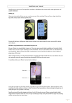
3.12 Terminal connection
3.12.1 Aftermarket configuration
OEM crash
sensor
UIM
Mic 2
Terminal connection in aftermarket configuration defined in Figure 1.
Mic 1
3.12.1.1
12V/24V power
Ignition
Radio audio out +/- 2
channels
Terminal ERA
Terminal audio out
+/- 2 channels
Radio mute
ISO 10487 connectors
Figure 1: Terminal connection
3.12.1.2
Terminal audio out (2 front speakers) shall be connected to vehicle audio system through ISO
10487 connectors.
3.12.1.3
If vehicle radio installed, then vehicle audio out (2 front speakers) shall be connected to
terminal through ISO 10487 connectors for audio commutation inside terminal.
3.12.1.4
Mute line shall be connected to vehicle radio through ISO 10487 connector.
3.12.1.5
Below interfaces are optional:
Mic 2 in
OEM crash sensor.
3.12.1.6
Below terminal connection schemes can be used in aftermarket configuration:
A: Vehicle with radio, stereo audio in, speakers and access to radio / speakers ISO connector: connect
radio front L/R out to terminal though ISO connector, terminal to speakers though ISO connector.
B: Vehicle with radio, stereo audio in, speakers and w/o access to radio / speakers ISO connector: the
main path to cut wires between radio and front L/R speakers and install as discussed in the case A. If
this is not possible to cut wires for specific vehicle, then install as discussed in the case D.
C: Vehicle with radio w/o stereo audio in with access to radio / speakers ISO connector: the same
connection as A.
ERA GLONASS Terminal
Navigation Information Systems JSC
Mandatory Requirements
Version 1.8
Page. 18
D: Vehicle with radio w/o stereo audio in and w/o access to radio / speakers ISO connector: connect
mute line to the radio, install additional speaker and connect the speaker to L or R channel of the
terminal amplified stereo audio out.
E: Vehicle w/o radio and with audio system with ISO connector: connect terminal to speakers though
ISO connector.
F: Vehicle w/o radio and w/o audio system with ISO connector: install additional speaker and connect
the speaker to L or R channel of terminal amplified stereo audio out.
3.12.2 OEM pre installed configuration
3.12.2.1
Terminal connection in OEM pre installed configuration to be defined by vehicle OEM.
ERA GLONASS Terminal
Navigation Information Systems JSC
Mandatory Requirements
Version 1.8
Page. 19
4. STANDARDS COMPLIANCE REQUIREMENTS
4.1
Radio electronic safety
4.1.1
Terminal shall satisfy below standards:
GOST 28751-90 – in the area of conduction noise in board systems;
GOST 28751-90 – ECU shall tolerate overvoltage in board system including reversed
connection of vehicle battery;
GOST 29157-91 – in the area of resistance to noise in control and signaling board circuits
from capacitor and inductive connections;
GOST R 50607-93 – in the area of resistance to noise from electrostatic pulse - per GOST R
50607-93;
GOST R 41.10-99 – in the area of radio noise from devices installed in vehicle;
GOST 28279-89 – in the area of electromagnetic compliance of vehicle pre installed devices
and vehicle customer radio electronic devices.
4.2
Resistance to external influences
4.2.1
Terminal shall satisfy below standards:
GOST R 52230 2004 – in the area of low atmospheric pressure for trucks working in
elevation up to 4650 meters above sea level, for atmospheric pressure as low as 57 kPA
(427,5 millimeters of mercury column);
GOST R 52230-2004 – moisture-proofness for devices of “XL” type, which corresponds to
the damp thermal environment during 4 days with temperature (40±2)оС and relative
moistness of (95±3)%;
GOST 14254-96 – degree of protection of electronic devices from penetration of foreign
matters, dust and water shall be in-line with IP52 code. IP52 code defines the following
protection characteristics:
The device is protected from dust (not full dust protection, but the duct shall not be in
quantity preventing device from regular work and scarifying safety);
Wire cannot access dangerous parts of the device (test probe with diameter 1,0 millimeter
cannot go inside the case);
Protected from vertically falling drops of water when case rotated up to 15° from vertical
position (vertically falling drops of water shall not alert device functions when case rotated
from version position to any side up to 15° inclusive);
ERA GLONASS Terminal
Navigation Information Systems JSC
Mandatory Requirements
Version 1.8
Page. 20
4.3
In addition, device shall be steady to washing liquids, gas, oil, salt and their steams.
Reliability requirements
4.3.1 Terminal shall satisfy GOST R 50905- 96 reliability requirements. Reliability shall be
characterized by:
Average time between failures;
Gamma percentage resource;
Average life cycle;
Period of storage.
Note: the above parameters will be defined in the next document version.
ERA GLONASS Terminal
Navigation Information Systems JSC
Mandatory Requirements
Version 1.8
Page. 21
4.4
Navigation performance requirements
4.4.1 Navigation module shall receive and process autonomously (jointly) GLONASS signal
(GLONASS and GPS signals) to calculate position and speed information.
4.4.2 Navigation data received from GLONASS system shall have higher priority comparing with
navigation data received from GPS system if this is impossible to receive trustable location and
speed information using GLONASS and GPS signals jointly.
4.4.3 In normal operating mode navigation module shall ensure location and speed accuracy not
worse than 30 meters and 0.1 meter per second per GOST R 52456-2005.
4.5
Ergonomic and industrial art requirements
4.5.1 Terminal and other units mechanical design and color scheme shall satisfy esthetical and
ergonomical requirements defined for vehicle cabin devices defined in GOST 12.2.049-80.
4.6
Constructional requirements
4.6.1 The same parts of terminal equipment shall be interchangeable. If a part changed, then
tuning and calibration shall not be required.
4.6.2
Mechanical design and size/installation factors shall be negotiated with OEM’s.
4.6.3
The case shall carry below information:
4.7
ECU name;
ECU serial number per ECU manufacturer guidelines;
Year of manufacturing;
Label of acceptance for equipment type;
Identification mark of connectors.
Safety and ecological requirements
4.7.1 Terminal shall be safe in storage, transportation and usage and follow sanitary andhygienic
regulations.
4.7.2 If user input sequence is out of order, then terminal shall not generate emergency
situation.
4.7.3 In terminal usage the driver shall be protected from electrical shock per defense class III in
line with GOST 12.2.007.0-75.
4.7.4 In terminal manufacturing inflammable and allocating harmful substances at burning
materials shall not be used per requirements of fire-prevention safety in line with GOST
ERA GLONASS Terminal
Navigation Information Systems JSC
Mandatory Requirements
Version 1.8
Page. 22
12.1.044-89.
ERA GLONASS Terminal
Navigation Information Systems JSC
Mandatory Requirements
Version 1.8
Page. 23
5. PRODUCT PACKAGE REQUIREMENTS
5.1
Product package
5.1.1
Product package in aftermarket configuration shall include the following:
TCU and TCU mounting materials
UIM and UIM mounting materials
Harness between TCU and UIM
Accelerometer with cable and accelerometer mounting materials (if accelerometer not embedded
to the main unit)
Microphone (microphone array) with cable and microphone (microphone array) mounting materials
Harness between TCU and vehicle electronics (vehicle adaptation kit)
Backup battery (preinstalled to TCU case)
Optional HF speaker with cable and HF speaker mounting materials
Owners user manual
Owner’s product brief brochure.
5.1.2
Product package in OEM pre installed configuration to be defined by OEM.
5.2
Additional documentation requirements
5.2.1
Installation manual shall be provided (only for aftermarket configuration).
5.2.2 Configuration and diagnostics / test manual shall be provided (only for aftermarket
configuration).
5.3
Branding requirements
5.3.1
UIM shall carry small ERA GLONASS logo. Small ERA GLONASS logo will be provided by NIS.
5.3.2 TCU shall carry extended ERA GLONASS logo. Extended ERA GLONASS logo will be provided
by NIS.
5.3.3
Owner’s user manual and product brief brochure shall carry small ERA GLONASS logo.
ERA GLONASS Terminal
Navigation Information Systems JSC
Mandatory Requirements
Version 1.8
Page. 24