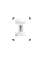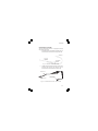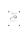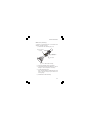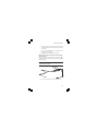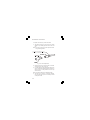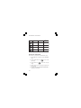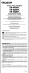
1
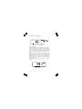
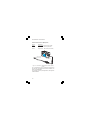
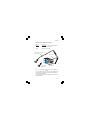
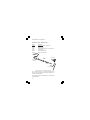
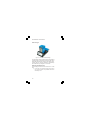
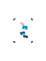
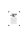
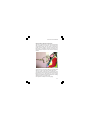
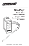
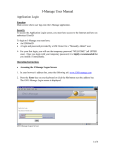
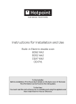
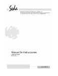
First Responder User Handbook FIRST RESPONDER - USER HANDBOOK Issue 2 31/10/06 Part Number: 42211 GMI welcomes comments on all our publications. Your comments can be of great value in helping us to improve our customer publications. Please send any comments that you have to our Sales Department at GMI. Contact details are provided inside the back cover of this handbook. Instrument Service / Repair contact details are also provided inside the back cover of this handbook. Copyright © Gas Measurement Instruments Ltd 2001 COPYRIGHT This User Handbook is copyright of Gas Measurement Instruments Ltd (GMI) and the information contained within is for use only with the First Responder instruments. Reproduction, in whole or in part, including utilisation in machines capable of reproduction or retrieval without written permission of Gas Measurement Instruments Ltd is prohibited. Reverse engineering is not permitted. LIABILITY Every care has been taken in the preparation of this document, but GMI Ltd do not accept any responsibility for errors or omissions and their consequences. Information in this document is subject to change without notice. This document does not constitute a specification or basis for a contract. Your statutory rights under law are not affected. MODIFICATION NOTICES GMI aim to notify customers of relevant changes in the product operation and maintain this manual up to date. In view of the policy of continuous product improvement there may be operational differences between the latest product and this manual. This Handbook is an important part of the First Responder product. Please note the following points: It should be kept with the instrument for the life of the product. Amendments should be attached. This Handbook should be passed on to any subsequent owner/user of the instrument. Although every care is taken in the preparation of this Handbook it does not constitute a specification for the instrument. SOFTWARE Software supplied on EPROM or similar device for use in a particular product, may only be used in that product and may not be copied without the written permission of Gas Measurement Instruments Ltd. Reproduction or disassembly of such embodied programmes or algorithms is prohibited. Ownership of such software is not transferable and GMI Ltd does not warrant that the operation of the software will be error free or that the software will meet the customers requirements. DISPOSAL ADVICE When no longer in use, dispose of the instrument carefully and with respect for the environment. GMI will dispose of the instrument without charge if returned to the factory. i FIRST RESPONDER - USER HANDBOOK SAFETY The instrument must be regularly serviced and calibrated by fully trained personnel in a safe area. Batteries: Alkaline batteries or *Rechargeable battery pack must be exchanged (*and recharged) in a safe area and fitted correctly before use. Never use damaged batteries or expose to extreme heat. See Section 5: OPERATOR MAINTENANCE. Only GMI replacement parts should be used. If the instrument detects gas, follow your own organisations procedures and operational guidelines. The combustion chamber is a flameproof assembly and must not be opened in the presence of a flammable atmosphere. First Responder instruments are certified as EEx iad IIB T3 o o (-20 C < Tamb < 50 C). BAS03ATEX2448X II 2 G. UL Class 1 Groups C and D. Use only Semiconductor Sensor (Flexi) Probe or Semiconductor Survey (Bellows) Probe with Certificate No. Sira ATEX2448X This equipment is designed and manufactured to protect against other hazards as defined in paragraph 1.2.7 of Annex II of the ATEX Directive 94/9/EC Any right of claim relating to product liability or consequential damage to any third party against GMI is removed if the warnings are not observed. AREAS OF USE Exposure to certain chemicals can result in a loss of sensitivity of the flammable sensor. Where such environments are known or suspected it is recommended that more frequent response checks are carried out. The chemical compounds that can cause loss of sensitivity include Silicones, Lead, Halogens and Sulphur. Do not use instrument in potentially hazardous atmospheres containing greater than 21% Oxygen. The enclosure material is polypropylene and must not be exposed to environments which are liable to result in mechanical or thermal degradation or to damage caused by contact with aggressive substances. Additional protection may be required in environments where the instrument enclosure is liable to damage. STORAGE, HANDLING AND TRANSIT The batteries in the rechargeable pack contain considerable energy and care should be taken in their handling and disposal. Battery packs should be removed if the instrument is stored for longer than 3 months. The instrument is designed to handle harsh environments. The sensing elements are sealed to IP54 and the rest of the instrument to IP64. If not subject to misuse or malicious damage, the instrument will provide many years of reliable service. The instrument contains electrochemical sensors with a life of 2 years. Under conditions of prolonged storage the sensors should be removed. The sensor contains potentially corrosive liquid and care should be taken when handling or disposing of the sensor, particularly when a leak is suspected. ii DECLARATION OF CONFORMITY iii FIRST RESPONDER - USER HANDBOOK iv REVISION RECORD Date Pages Description Of Change Issue 1 18/04/02 All New Handbook Issue 2 31/10/06 All To include Declaration of Conformity and the effect of CR 2302, CR 2319 and CR 4042 v FIRST RESPONDER - USER HANDBOOK vi CONTENTS COPYRIGHT ................................................................... i LIABILITY ....................................................................... i MODIFICATION NOTICES ................................................ i SOFTWARE ................................................................... i DISPOSAL ADVICE ........................................................ i SAFETY ......................................................................... ii AREAS OF USE ............................................................. ii STORAGE, HANDLING AND TRANSIT .......................... ii DECLARATION OF CONFORMITY ................. iii REVISION RECORD ....................................... v INTRODUCTION .......................................... 1-1 GENERAL INFORMATION .......................... 2-1 Ranges of Operation ................................................. 2-1 EXT Range (External Semiconductor Sensor), 0 10,000 ppm Flammable ..................................... 2-1 ppm Flammable, 0 1000 ppm ................................ 2-3 LEL, 0 to 100% ........................................................ 2-4 vii FIRST RESPONDER - USER HANDBOOK Volume Gas, 0 to 100 % ......................................... 2-5 Carbon Monoxide, 0 1000 ppm ............................ 2-5 Alarms ........................................................................ 2-6 LEL and CO Ranges ................................................ 2-6 Alarm Functions ...................................................... 2-6 PPM Flammable and EXT Range Geiger .................. 2-7 Datalogging ................................................................ 2-7 Automatic Datalogging ............................................ 2-7 Manual Datalogging ................................................. 2-8 Construction .............................................................. 2-8 Batteries ..................................................................... 2-9 Alkaline (LR20) Batteries ........................................ 2-9 Rechargeable Battery Pack .................................... 2-9 Filters ....................................................................... 2-10 Probe Handle Assembly - Part No. 12481 ............ 2-10 Semiconductor Sensor Flexi Probe Assembly - Part No. 42200 .............................................................. 2-10 Semiconductor Survey Bellows Probe Assembly Part No. 42444 ...................................................... 2-10 Probe Handle Assembly - Part No. 13561 ............ 2-11 Liquid Crystal Display (LCD) ................................... 2-11 Before Use Checks ................................................. 2-11 viii CONTENTS OPERATING INSTRUCTIONS ..................... 3-1 Instrument Features .................................................. 3-1 Switch Panel .............................................................. 3-2 Connection of Probe .................................................. 3-3 Measure Operation .................................................... 3-5 Switching On .......................................................... 3-5 Calibration Date Features (Option) ......................... 3-6 Switching Off the Instrument Pump ........................ 3-7 Switching Off .......................................................... 3-7 Changing Range ...................................................... 3-7 Datalogging (Default) .............................................. 3-8 Clearing Alarms ....................................................... 3-8 Activate the Audible Geiger Indication (EXT or PPM Flammable Range) ............................. 3-8 Zeroing the PPM Flammable or EXT Range ............ 3-9 Adjust Threshold Value in EXT Range .................... 3-9 Barhole Probing Counter ....................................... 3-10 Notes on Measure Operation: ............................... 3-11 Summary of Switch Operation ............................. 3-11 Operator Messages / Fault Flags ......................... 3-12 ix FIRST RESPONDER - USER HANDBOOK PROBES .................................................... 4-1 Standard Probe and Handle Assembly ................... 4-1 Semiconductor Sensor (EXT) Probe ...................... 4-2 Semiconductor (EXT) Survey Probe ...................... 4-3 Swan Neck Probe / Bellows Probe ........................ 4-4 OPERATOR MAINTENANCE ...................... 5-1 Rechargeable Battery Pack ....................................... 5-1 Standard Charger .................................................... 5-1 Smart Charger ......................................................... 5-2 Replacing the Battery Pack ..................................... 5-2 Recharging the Battery Pack .................................. 5-4 Replacing Alkaline (LR20) Batteries .......................... 5-4 Filter Replacement ..................................................... 5-6 Probe Handle Assembly - Part No. 12481 .............. 5-6 Probe Handle Assembly - Part No. 13561 .............. 5-8 Semiconductor Survey Bellows Probe Assembly Part No. 42444 ...................................................... 5-11 Flue Probe Coalescing Filter Assembly - Part No. 42215 .................................................................... 5-14 Semiconductor Sensor (Flexi) Probe Assembly - Part No. 42200 .............................................................. 5-15 x CONTENTS CALIBRATION ............................................. 6-1 Calibration Validity ...................................................... 6-2 ACCESSORIES .......................................... 7-1 ADDITIONAL INFORMATION ....................... 8-1 Training ...................................................................... 8-1 World Wide Web ........................................................ 8-1 TYPICAL OPERATING PARAMETERS ....... A-1 Size ........................................................................ A-2 Weight .................................................................... A-2 Operating Temperature .......................................... A-2 Humidity .................................................................. A-2 Construction ........................................................... A-2 Display .................................................................... A-2 Sampling System .................................................... A-2 Power Source ........................................................ A-3 xi FIRST RESPONDER - USER HANDBOOK FIELD CALIBRATION .................................. B-1 Selectable Ranges in FCM ........................................ B-2 Entering FCM ............................................................. B-3 Zeroing the Instrument ............................................. B-4 Field Calibration Procedure ....................................... B-5 Quitting FCM .............................................................. B-8 Quit and Save Changes ......................................... B-8 Quit Without Saving Changes ................................ B-9 APPLICATIONS .......................................... C-1 Small Plastic (Solid End) Probe .............................. C-1 Semiconductor Sensor (Flexi) Probe .................... C-3 Semiconductor Survey (Bellows) Probe .............. C-6 Bellows Probe ........................................................ C-8 Swan Neck Probe .................................................. C-9 Stainless Steel (Flue) Probe .................................. C-11 INDEX ............................................................. I xii 1 INTRODUCTION The First Responder is a combination instrument for first call and emergency response technicians in the gas utilities industry. Fig. 1-1 First Responder The instrument is a highly flexible, four button portable gas detector which is designed to provide measurement of Lower Explosive Level (LEL) and Volume flammable gas for leak detection and general safety monitoring. The First Responder also features a Parts Per Million (PPM) 1-1 FIRST RESPONDER - USER HANDBOOK flammable range to increase sensitivity to smaller leaks and a Carbon Monoxide (CO) range for internal atmosphere monitoring where odour call response is required. This instrument has the added advantage of providing the option of two external (EXT) range diffusion probes. The first is a Semiconductor Sensor Flexi Probe, which features a high speed sensor to enable rapid response in detecting small fitting leaks. The second is a Semiconductor Survey Bellows Probe which features the same high speed sensor but has the added advantage of providing an almost instantaneous response by pumping the sample past the sensor thus eliminating any delay in diffusion. These high speed response and sensitivity Semiconductor Sensor Probes also enable initial external leakage surveys to be performed in the vicinity of property or pipelines enabling distribution leaks to be quickly found. The instrument monitors all gases continuously, providing all round protection for users. The First Responder is equipped with both audible and visual alarms and Geiger indications on the EXT and PPM flammable ranges. The First Responder contains the following ranges: 1-2 0 to 10,000 ppm flammable EXT Range (External Semiconductor Sensor) 0 to 1000 ppm Flammable 0 to 100% LEL 0 to 100% Volume gas 0 to 1000 ppm Carbon Monoxide INTRODUCTION The First Responder has a variety of user configurable options. This handbook details the default configuration, with possible options detailed in italic text. The First Responder instrument and both Semiconductor Sensor Probes are listed by Underwriters Laboratories , and are classified for use in Hazardous Locations Class 1, Groups C and D. The First Responder is supplied in a carrying case with a selection of accessories. For a comprehensive list of accessories supplied with the instrument, and additional accessories available, see Section 7 ACCESSORIES. The main features of the instrument are: Rugged polypropylene case, sealed to IP54 rating and suitable for outdoor use. Four button operation allowing the user access to all features. LCD with backlighting which displays the current gas readings (in both digital and analogue forms) together with operational and status information. Audible and visual alarms with alarm levels preset. Manual and automatic datalogging. Directly interfaces with the GMI Auto Test Calibration Units. 1-3 FIRST RESPONDER - USER HANDBOOK 1-4 2 GENERAL INFORMATION Ranges of Operation The instrument calibration gas is shown on the instrument service label. EXT Range (External Semiconductor Sensor), 0 10,000 ppm Flammable This range displays flammable gas parts per million (ppm) content up to 9999 ppm. When this range is selected, EXT for external, is displayed in the top right corner of the LCD. The EXT range, by default, has the audible and visual Geiger indication configured, that is, they will provide assurance that the instrument is sensing for gas without the need for the operator to constantly view the display. When the instrument is switched on, the visual Geiger indication is operational. To activate the audible Geiger indication, press Switch Four ( ). Each single press ) will toggle the audible Geiger of Switch Four ( indication On and Off. When the audible Geiger is activated, the display changes between EXT and Aud, as shown in Figure 2-1. 2-1 FIRST RESPONDER - USER HANDBOOK Fig. 2-1 EXTernal Range The instrument is configured such that in the EXT range, a threshold is enabled which will display a zero (0) reading up to a pre-set level. This allows small readings, which may not be due to the gas we wish to find, or very small amounts of gas, to be ignored if they fall below any pre-set action levels. This allows the operator to react only to significant levels. The factory set threshold level is ten (10) ppm. When the EXT range is selected, you can view the threshold value. To do this, press and hold Switch Two ( ). The threshold value will alternate with the range name as shown in Figure 2-2. Press and hold Switch Two ( ) again, to return to current sample reading. Fig. 2-2 EXTernal Range Threshold 2-2 GENERAL INFORMATION ppm Flammable, 0 1000 ppm This range is used to measure very low levels of gas and indicates the parts per million concentration of the gas in air (1000 ppm is equivalent to 0.1% Volume Gas). Above 1000 ppm flammable, the instrument autoranges to LEL. When the ppm flammable range is selected, PPM is displayed in the top right corner of the LCD. The digital display reading resolves to 5 ppm with the analogue bargraph following in steps of 40 ppm. The ppm flammable range is more sensitive than LEL and Volume ranges and takes longer to stabilise. The detection principle is a catalytic reaction with the sensitivity of the sensors, greatly enhanced compared to the LEL range. Digital signal correction techniques are used to minimise drift. The ppm flammable range includes a manual zeroing facility. The ppm flammable range, by default, has the audible and visual Geiger indication configured, that is, they will provide assurance that the instrument is sensing for gas without the need for the operator to constantly view the display. When the instrument is switched on, the visual Geiger indication is operational. To activate the audible Geiger indication, press Switch Four ( ). Each single press of Switch Four ( ) will toggle the audible Geiger indication On and Off. When the audible Geiger is activated, the display changes between PPM and Aud, as shown in Figure 2-3. 2-3 FIRST RESPONDER - USER HANDBOOK Fig. 2-3 PPM Range LEL, 0 to 100% The LEL range indicates the explosibility of the flammable gas in the sample. This is displayed as a percentage of the lower explosive limit (LEL) of the gas. For methane 100% LEL corresponds to 5% Volume methane in Air. Above 100% LEL, the instrument autoranges to Volume Gas. When the LEL range is selected, LEL is displayed in the top right corner of the LCD. From 0 to 10% LEL the digital display resolves to 0.1% LEL. From 10 to 100% LEL the digital display resolves to 1% LEL. The analogue bar graph follows in 4% steps. An example of the LEL display is shown in Figure 2-4. The detection principle for this range is a catalytic reaction. Fig. 2-4 LEL Range 2-4 GENERAL INFORMATION Volume Gas, 0 to 100 % This range displays the total volume of flammable gas with respect to air. When the Volume Gas range is selected, GAS is displayed in the top right corner of the LCD. The digital display resolves the signal to 1% GAS with the analogue bar graph following in steps of 4%. Figure 2-5 shows the Volume Gas display. The detection principle for the Volume Gas range is thermal conductivity. Fig. 2-5 Volume Gas Range Carbon Monoxide, 0 1000 ppm This range displays the parts per million (ppm) Carbon Monoxide content up to 999 ppm. When the Carbon Monoxide range is selected, CO is displayed in the top right corner of the LCD. The digital display resolves to 1 ppm CO. The analogue bar graph follows in 40 ppm steps. Above 1000 ppm, EEEE is displayed. Figure 2-6 shows the Carbon Monoxide display. The Carbon Monoxide sensor is subject to the effect of pressure transients and should be operated at normal atmospheric pressure conditions. The sensor has a normal operating life of two years. 2-5 FIRST RESPONDER - USER HANDBOOK Fig. 2-6 Carbon Monoxide Range Alarms LEL and CO Ranges Both the LEL and CO ranges have, by default, audible and visual alarms active. The audible alarm is rated up to 85 dB(A) at 0.3m (1ft.) approx. The visual alarm is a red LED indicator which protrudes from the instrument top plate, allowing viewing from any angle above the top plate. It is the responsibility of the user to ensure that the alarm levels, where set in the instrument, are appropriate for the safe operation and legal requirements for the country / industry in which the unit is being used. The First Responder has the high instantaneous alarm level setting of 35 ppm CO and 20% LEL activated by default. Other values can be set if required. Alarm Functions For Flammable LEL and Carbon Monoxide ranges in the instrument, the alarm function default is that the alarms will be non-latching and both the audible and visual functions will operate. That is, where an alarm level is exceeded, the instrument LED flashes and the sounder pulses rapidly. These alarms clear automatically when the gas levels fall below the alarm limit. 2-6 GENERAL INFORMATION Non-latching alarms can be acknowledged by a double press of Switch Four ( ). If, after 60 seconds, the gas detected still exceeds the alarm level, the audible and visual alarm will be re-activated. When an alarm limit for either the Flammable LEL or Carbon Monoxide range is exceeded, the LCD automatically displays the range in alarm. If both alarms are active, the LEL alarm will be displayed as this has a higher priority than CO. PPM Flammable and EXT Range Geiger The EXT range and the PPM Flammable range have, by default, audible and visual Geiger indication configured. This means that, as the gas concentration increases, the sounder (if activated), and the LED, pulse at an increasing rate. Datalogging The First Responder provides the user with both automatic and manual datalogging functions. Automatic Datalogging By default, the instrument has automatic datalogging enabled and is confirmed by the STORE flag being displayed, as shown in Figure 2-7. Fig. 2-7 Automatic Datalogging Enabled 2-7 FIRST RESPONDER - USER HANDBOOK During automatic datalogging the instrument stores the values of all gas ranges together with the current time and date at 60 second intervals. Automatic datalogging can be disabled by a double press of Switch Two ( ). The STORE flag will be extinguished if automatic datalogging is disabled. Manual Datalogging Manual datalogging allows the user to store a snapshot reading at any point, by a double press of Switch Three ( ). This is confirmed by the STORE flag being displayed for 1 second and the buzzer sounding. Construction The instrument is housed in a tough, impact resistant, moulded case made of polypropylene. The top panel is protected by a stainless steel top plate covering a toughened glass LCD cover. The battery cover (Alkaline) / Battery Pack (Rechargeable) is attached to the main instrument body by means of two stainless steel hexagonal screws. The instrument is sealed against dust and water to IP54 standard. The instrument sensors are protected from dust and water by membrane and cotton filters, when using probe handle assembly (Part No. 12481). Other probes with associated filters are available as accessories. 2-8 GENERAL INFORMATION Batteries Alkaline (LR20) Batteries Alkaline batteries provide approximately 18 hours operational life, (12 hours with external semiconductor sensor flexi probe or semiconductor survey bellows probe connected), at ambient temperature of 15oC to 20oC (59oF to 68oF). When the batteries are low or exhausted it is necessary to fit 4 new batteries to reset the battery indicator to 100%. Do not mix old and new batteries. An indication of the battery life is displayed during warm up. During operation the BAT alarm flag is displayed when 1 to 2 hours of operating time remain at normal temperature. The instrument may still be used but eventually the BAT FAULT alarm flag will be displayed, shortly after which the instrument will switch off automatically. Rechargeable Battery Pack The GMI rechargeable battery pack is identified, when fitted, by two contacts on end face of pack and provides approximately eight hours of use from fully charged condition. An indication of the battery life is displayed during warm up. During operation the BAT flag is displayed when approximately 30 minutes operating time is left at normal temperature. The instrument may still be used but eventually the BAT FAULT alarm flag will be displayed, shortly after which the instrument will switch off automatically. There are two GMI Battery Chargers available, a Standard Charger and a Smart Charger. The Smart Charger has both slow and fast charge options as well as a serial link for communications with the instrument. See Rechargeable Battery Pack in Section 5 OPERATOR MAINTENANCE. 2-9 FIRST RESPONDER - USER HANDBOOK Filters Probe Handle Assembly - Part No. 12481 A number of different filter types are available from GMI. The minimum requirement is a cotton particulate filter and a hydrophobic filter. These filters, incorporated in the probe handle assembly, are available from GMI. Filters must be checked at frequent intervals and where appropriate changed to ensure a clean sample path. Any filter which has been contaminated must be cleaned or replaced. See Filter Replacement in Section 5 OPERATOR MAINTENANCE. Semiconductor Sensor Flexi Probe Assembly - Part No. 42200 A replacement filter disc, which is incorporated in the Probe end cap, is available from GMI. Filters should be checked periodically and where appropriate changed to ensure a clean sample path. Any filter which has been contaminated must be replaced. See filter replacement instructions in Section 5 OPERATOR MAINTENANCE. Semiconductor Survey Bellows Probe Assembly - Part No. 42444 A replacement Dust Filter disc, which is incorporated in the Semiconductor Survey Bellows Probe, is available from GMI. A Water Filter assembly is available as an accessory for use with this probe. Filters should be checked periodically and, where appropriate, changed to ensure a clean sample path. Any filter which has been contaminated must be cleaned or replaced. See Filter Replacement in Section 5 OPERATOR MAINTENANCE. 2-10 GENERAL INFORMATION Probe Handle Assembly - Part No. 13561 A Water or Dust Filter Assembly is available from GMI for use with this probe handle. Either of the filter assemblies can be attached to the probe handle. Filters must be checked at frequent intervals and where appropriate changed to ensure a clean sample path. Any filter which has been contaminated must be cleaned or replaced. See Filter Replacement in Section 5 OPERATOR MAINTENANCE. Liquid Crystal Display (LCD) The LCD shows the current gas readings in both analogue and digital form together with operational and status information. The display is protected by a toughened glass cover. Backlighting is provided to enable the display to be seen under low ambient light conditions. Before Use Checks The following checks should be carried out before using the instrument on site: The instrument is clean and in good condition. The batteries have sufficient power left in them for the intended use of the instrument. The filters are clean and in good condition. The sample line and aspirator bulb (if used) and any accessories are in good condition and leak free. Use only Semiconductor Sensor (Flexi) Probe or Semiconductor Survey (Bellows) Probe with Certificate No. Sira ATEX2448X (if applicable) 2-11 FIRST RESPONDER - USER HANDBOOK All gas ranges are operational and zeroed correctly. The calibration is still valid. 2-12 3 OPERATING INSTRUCTIONS Instrument Features The First Responder front plate features a panel of four operating switches, a backlit LCD screen incorporating the analogue bar graph, a visual alarm LED and an infra red communication port. Fig. 3-1 Instrument Front Plate 3-1 FIRST RESPONDER - USER HANDBOOK Switch Panel The First Responder Switch Panel features four operating switches, as shown in Figure 3.2 A Single Press of any switch will access functions, coloured red, on left hand side of switch panel. A Double Press of any switch will access functions, coloured blue, on right hand side of switch panel. ON PUMP OFF RANGE AUTO LOG ZERO MAN LOG AUD ALARM ALARM ACK. Fig. 3-2 Switch Panel The symbols indicate the operator actions necessary to access all instrument functions: SINGLE PRESS (functions in red) DOUBLE PRESS (functions in blue) SINGLE PRESS and HOLD (to turn instrument ON) Refer also to paragraph Summary of Switch Operation later in this chapter. 3-2 OPERATION Connection of Probe The First Responder instrument is equipped to accept three probe input types. 1. A Standard Probe and Handle assembly which is connected to the instrument via sample line inlet. Fig. 3-3 Standard Probe and Handle 2. The EXT range Semiconductor Sensor Flexi Probe provides fast response gas detection and is connected to the instrument via an 8-Pin Plug. Flexible Probe 8-Pin instrument connector plug Probe Sensor Fig. 3-4 Semiconductor Sensor Flexi Probe 3-3 FIRST RESPONDER - USER HANDBOOK 3. The EXT range Semiconductor Survey Bellows Probe, which provides fast response gas detection, is connected to the instrument via both an 8-Pin Plug and sample line inlet. 8-Pin Instrument Connector Plug Sample Line Probe Sensor Fig. 3-5 Semiconductor Survey Bellows Probe Instrument connection points for the three types of probe are shown in Figure 3-6 3-4 OPERATION Connection for 8-Pin Probe Connector Plug Connection for Probe Sample Line Fig. 3-6 Probe Connection Measure Operation Switching On Pressing and holding Switch One ( ) turns both the instrument and the pump ON. This initiates the instruments warm up cycle, as shown in the following example sequence, Figure 3-7. The display of alarm levels after the warm up sequence may be cancelled by a single press of any switch. 3-5 FIRST RESPONDER - USER HANDBOOK Current detection reading Fig. 3-7 Warm Up Calibration Date Features (Option) At the end of warm-up and before the first Responder instrument is ready for measuring, the instrument will indicate on the display when the next calibration is due. This will be displayed as month and year, as shown in Figure 3-8: Calibration Due December 2002 (Alternate flash) Fig. 3-8 Calibration Date 3-6 OPERATION The re-calibration interval pre-set for all First Responder instruments is twelve (12) months. This period can be altered, however, you should ensure that the instrument is always within its calibration period prior to use. Switching Off the Instrument Pump A single press of Switch One ( ), when the pump is running, turns the pump off and stops sampling. Pressing switch one again turns the pump back on. The SAMPLE flag is displayed when the pump is running and is extinguished when the pump is switched off. Switching Off A double press of Switch One ( off. ) turns the instrument There is a five second shutdown sequence during which time, OFF is displayed in the top right hand corner of the display. Single press any one of the four instrument switches to abort shutdown. Changing Range Each single press of Switch Two ( ) changes the range. The display cycles through the available ranges in the order: LEL PPM CO EXT LEL etc. Note: The instrument auto-ranges between LEL and Volume Gas. The instrument also autoranges between PPM, LEL and Volume Gas. 3-7 FIRST RESPONDER - USER HANDBOOK Datalogging (Default) A double press of Switch Three ( ) initiates a manual datalog. This is confirmed by the buzzer sounding and, if auto datalogging is disabled, the STORE flag being displayed for 1 second. A double press of Switch Two ( ) toggles automatic datalogging on and off. When automatic datalogging is on, the STORE flag is permanently displayed. Clearing Alarms A double press of Switch Four ( the alarm for 60 seconds. ) will acknowledge If more than one gas alarm threshold has been exceeded, a double press of Switch Four ( each alarm in order of priority. ) will acknowledge Activate the Audible Geiger Indication (EXT or PPM Flammable Range) Where the First Responder has the EXT range or the PPM Flammable range selected then, by default, the visual Geiger indication will be enabled. A single press of Switch Four ( ) will activate the audible Geiger indication. Each further press of Switch Four ( audible Geiger indication Off and On. 3-8 ) will toggle the OPERATION Zeroing the PPM Flammable or EXT Range Both the EXT range and the PPM Flammable range can be manually zeroed. To zero, a single press of Switch Three ( ) is required and should be carried out in fresh air. The display in Figure 3-9 occurs if a large adjustment is needed to reach the zero point. Fig. 3-9 Zeroing Range Adjust Threshold Value in EXT Range With the EXT range selected, you can adjust the threshold value. To do this, press and hold Switch Two ( display the factory default ten (10) ppm setting. ) to Each single press of Switch Three ( the threshold value by five (5) ppm. ) will increase Each single press of Switch Four ( the threshold value by five (5) ppm. ) will decrease The minimum threshold value is zero (0) ppm and the maximum value is 200 ppm. The display will roll over to zero (0) following the 200 ppm selection. 3-9 FIRST RESPONDER - USER HANDBOOK Note: If no buttons are pressed for 30 seconds, the display will return to EXT sampling. When adjustment is complete, press and hold Switch Two ) to save the new default value and return to the ( current sample reading. Barhole Probing Counter The First Responder is enabled to allow the user to start and stop a timer, to assist in barhole probing. For an illustrated example of barhole probing, see Appendix C APPLICATIONS. To start or stop the counter, press and hold Switch Three ( ) when the current range is either LEL or Volume gas. The count, in seconds, alternates with the range as shown in Figure 3-10. Fig. 3-10 Barhole counter activated (showing 5 secs.) The counter will roll over from 999 to 000. When the counter is activated and the range switch is pressed, the counter will still increment, although it will only be displayed when the range is LEL or Volume gas. 3-10 OPERATION Notes on Measure Operation: Alarms are always enabled. The pump can be switched ON or OFF. The instrument does not switch off automatically. Automatic datalogging is enabled by default. Summary of Switch Operation Fig. 3-11 Switch Operation 3-11 FIRST RESPONDER - USER HANDBOOK Operator Messages / Fault Flags Various messages can appear on the LCD screen to indicate instrument status. SAMPLE This indicates that the pump is running and the instrument is sampling. OFF This indicates that the instrument is about to switch off. This command can be cancelled by a single press of any switch. FAULT When in EXT range, this message is displayed if the Semiconductor Sensor Probe is not connected. SAMPLE FAULT This indicates a problem with the instruments flow due to the sample path being blocked, water ingress, a blocked filter or pump failure. The instrument will alarm and the pump will switch off. The sample path should be checked and Switch One pressed to clear sample fault and re-start the pump. CHECK ZERO This indicates that there may have been a zero shift due to the presence of gas. Switch off the instrument and switch on again in fresh air. 3-12 OPERATION ZERO FAULT This indicates that the zero is outwith its calibration limits. Switch the instrument off and then on again in fresh air. If the fault does not clear, return the instrument for servicing. BAT This indicates that the batteries will soon require replacement. At this point there will be approximately 1 to 2 hours left in a set of alkaline batteries, although this figure will vary depending on battery manufacturer, temperature conditions, usage etc. With rechargeable batteries the BAT flag indicates approximately 30 minutes operation left. BAT FAULT This indicates that the batteries should be replaced immediately. As the battery power continues to fall, the pump switches off and the LCD flashes a BAT FAULT message. Subsequently the LCD displays OFF and the instrument switches off after approximately 5 minutes. The batteries should be replaced immediately. STORE This flag is displayed when the instrument is in auto datalogging mode. During manual datalogging, if not already on, the flag will be displayed for approximately one second. EEEE EEEE is displayed if the measurement in the EXT range rises above 9999 (instrument over range) or PPM flammable range measurement rises above 999. 3-13 FIRST RESPONDER - USER HANDBOOK 1 This message which can also appear after power on, indicates that a calibration data error has been detected. The instrument should be returned for servicing. 3-14 4 PROBES The First Responder instrument is equipped to accept the following probes and associated accessories: Standard Probe and Handle Assembly Part No. Description 12480 Small Plastic Probe 12481 Probe Handle Assembly - incl. filters 12688 Probe Adaptor (not shown) 12712 Clear Sample Line x 1.5 Metres (4ft 10ins.) approx. Fig. 4-1 Instrument / Standard Probe 4-1 FIRST RESPONDER - USER HANDBOOK Semiconductor Sensor (EXT) Probe Part No. Description 42200 Semiconductor Sensor (Flexi) Probe Assembly incl. End Cap with Filter 42169 Carry Pouch - Flexi Probe (not shown) Semiconductor Sensor Probe 8-Pin DIN Plug Fig. 4-2 Instrument / Semiconductor Sensor (Flexi) Probe For a comprehensive list of accessories supplied with the instrument, and additional accessories available, see Section 7 ACCESSORIES. For examples of various probe applications, see Appendix C APPLICATIONS. 4-2 PROBES Semiconductor (EXT) Survey Probe Part No. Description 42444 Semiconductor Survey (Bellows) Probe Assembly incl. Dust Filter 42416 Water Filter Assembly Semiconductor Survey Probe c/w Dust Filter Sample Line Water Filter Assembly 8-Pin DIN Plug Fig. 4-3 Instrument / Semiconductor Survey (Bellows) Probe For a comprehensive list of accessories supplied with the instrument, and additional accessories available, see Section 7 ACCESSORIES. For examples of various probe applications, see Appendix C APPLICATIONS. 4-3 FIRST RESPONDER - USER HANDBOOK Swan Neck Probe / Bellows Probe Part No. Description 13655 Swan Neck Probe c/w Shroud 13563 Bellows Probe 13561 Probe Handle Assembly incl. Sample Line 13562 Probe Adaptor 42184 Dust Filter Assembly 42183 Water Filter Assembly connects to instrument inlet Bellows Probe Probe Handle Assembly Filter Assembly Probe Adaptor Swan Neck Probe Fig. 4-4 Bellows / Swan Neck Probes For a comprehensive list of accessories supplied with the instrument, and additional accessories available, see Section 7 ACCESSORIES. For examples of various probe applications, see Appendix C APPLICATIONS. 4-4 5 OPERATOR MAINTENANCE Rechargeable Battery Pack Two battery chargers are available from GMI, a Standard Charger and a Smart Charger. Standard Charger Fig. 5-1 Instrument / Standard Charger The GMI Standard Charger takes approximately 14 hours to charge a flat battery. 5-1 FIRST RESPONDER - USER HANDBOOK Smart Charger Fig. 5-2 Instrument / Smart Charger The GMI Smart Charger provides both fast and standard charging facilities. It can charge an instrument and a spare battery pack simultaneously. Using the fast charge option, a battery pack can be 90% recharged in approximately 60 minutes and fully recharged in 120 minutes. Replacing the Battery Pack The following procedure should be carried out in a safe area: 1) Loosen the two instrument base screws (4mm hex) using the special tool provided and remove the battery cover. 5-2 OPERATOR MAINTENANCE Fig. 5-3 Loosen Instrument Base Screws 2) Remove the battery pack. Fig. 5-4 Remove Battery Pack 5-3 FIRST RESPONDER - USER HANDBOOK 3) Insert new battery pack. 4) Fasten base screws. 5) Check that instrument switches on and works to specification. Recharging the Battery Pack The battery pack should be recharged in the following situations: The BAT or BAT FAULT message is displayed. The instrument will not switch on. The pump will not switch on. It is recommended that the battery pack is fully discharged on a regular basis (once every three months). This can be done by running the instrument continuously or using the battery conditioning facility on the Smart Charger. The batteries can be charged on the instrument but the instrument itself should be switched off. Regular complete discharge will keep the battery pack in good condition. Replacing Alkaline (LR20) Batteries All four batteries should be replaced at any one time and in a safe area. GMI only recommend the use of Energizer or Duracell cells. 1) Loosen the two instrument base screws (4mm hex) using the special tool provided. 5-4 OPERATOR MAINTENANCE Fig. 5-5 Loosen Instrument Base Screws 2) Remove battery cover. Fig. 5-6 Remove Battery Cover 3) Remove the old batteries. 5-5 FIRST RESPONDER - USER HANDBOOK 4) Check battery compartment for damage to spring contacts or corrosion on springs. Caution: Under no circumstances should rechargeable batteries be fitted in place of alkaline. 5) Insert four new batteries observing correct polarity indication in battery compartment base. 6) Replace battery cover and fasten base screws. 7) Check that the instrument switches on and works to specification. Filter Replacement Probe Handle Assembly - Part No. 12481 Hydrophobic and cotton particulate filters in the probe handle minimise the danger of water and dust ingress. Caution: The instrument should never be switched on without suitable filters installed. If a blockage occurs the SAMPLE FAULT indicator is displayed. Check the sample line and probe handle for blockage. Press Switch One ( ) to clear the SAMPLE FAULT message. Replace the filter(s) if the message does not clear. To replace the filter(s), proceed as follows: 5-6 OPERATOR MAINTENANCE 1) Unscrew the probe handle assembly. Cotton Particulate Filter Hydrophobic Filter Probe Handle Assembly Fig. 5-7 Filter Assembly 2) Remove the cotton particulate filter and discard. 3) Remove the hydrophobic filter. 4) Clean the probe handle to make sure that it is free from dirt and water. 5) Fit a new cotton particulate filter. 6) Fit the hydrophobic filter. The yellow label on the filter fits against the yellow label on the probe handle. 7) Reassemble the probe handle assembly. 5-7 FIRST RESPONDER - USER HANDBOOK Probe Handle Assembly - Part No. 13561 Fitting of an In-line filter assembly to the probe handle, as shown in Figure 5-8, will minimise the danger of water and / or dust ingress. . Fig. 5-8 Probe Handle and In-line Filter Assembly Caution: The instrument should never be switched on without suitable filters installed. If a blockage occurs the SAMPLE FAULT indicator is displayed. Check the sample line and filter assembly for blockage. Press Switch One ( ) to clear the SAMPLE FAULT message. Replace the filter if the message does not clear. 5-8 OPERATOR MAINTENANCE In-line Dust Filter To replace the Dust Filter in the Dust Filter Housing assembly, proceed as follows: 1) Unscrew the filter housing assembly (Figure 5-9). Probe Sealing Washer Dust Filter Probe Washer Dust Filter Housing Assembly Fig. 5-9 Dust Filter Assembly 2) Remove Dust Filter, then discard. 3) Check Probe Washer and Probe Sealing Washer for signs of damage or wear and replace if necessary. 4) Fit new Dust Filter. 5) Reassemble the Filter Housing assembly. 5-9 FIRST RESPONDER - USER HANDBOOK In-line Water Filter To replace the Hydrophobic Filter in the Water Filter Housing assembly, proceed as follows: 1) Unscrew the filter housing assembly (Fig. 5-10). Water Filter Housing Assembly Hydrophobic Filter Probe Sealing Washer Probe Washer yellow label Fig. 5-10 Water Filter Assembly 2) Remove Hydrophobic Filter, then discard. 3) Check Probe Washer and Probe Sealing Washer for signs of damage or wear and replace if necessary. 4) Fit new Hydrophobic Filter. Note: The filter should be installed with the yellow label on the filter, facing the yellow label on the housing flange. 5) Reassemble the Filter Housing assembly. 5-10 OPERATOR MAINTENANCE Semiconductor Survey Bellows Probe Assembly - Part No. 42444 The dust filter assembly can be removed, as shown in Fig. 5-11, and replaced with a water filter assembly. The water filter assembly is available as an accessory. Replace the probe sealing washer if it shows signs of damage or wear. Probe Sealing Washer Fig. 5-11 Semiconductor Survey Bellows Probe Filter Assembly Caution: The instrument should never be switched on without suitable filters installed. If a blockage occurs the SAMPLE FAULT indicator is displayed. Check the sample line and filter assembly for blockage. Press Switch One ( ) to clear the SAMPLE FAULT message. Replace the filter if the message does not clear. 5-11 FIRST RESPONDER - USER HANDBOOK Dust Filter To replace the Dust Filter in the Dust Filter assembly, proceed as follows: 1) Unscrew the filter assembly (Fig. 5-12). Dust Filter Housing Assembly Dust Filter Probe Washer Fig. 5-12 Dust Filter Assembly 2) Remove Dust Filter, then discard. 3) Check Filter assembly Probe Washer for signs of damage or wear and replace if necessary. 4) Fit new Dust Filter. 5) Reassemble the Filter assembly. 5-12 OPERATOR MAINTENANCE Water Filter (Accessory) To replace the Hydrophobic Filter in the Water Filter assembly, proceed as follows: 1) Unscrew the filter assembly (Fig. 5-13). Water Filter Housing Assembly Hydrophobic Filter Assembly Probe Washer Fig. 5-13 Water Filter Assembly 2) Remove Hydrophobic Filter, then discard. 3) Check Filter assembly Probe Washer for signs of damage or wear and replace if necessary. 4) Fit new Hydrophobic Filter. Note: The filter should be installed with the yellow label on the filter, facing the yellow label on the housing flange. 5) Reassemble the Filter assembly. 5-13 FIRST RESPONDER - USER HANDBOOK Flue Probe Coalescing Filter Assembly - Part No. 42215 A coalescing filter is fitted in the filter bowl and housing assembly to minimise the danger of water ingress. Caution: The instrument should never be switched on without suitable filters installed. If a blockage occurs the SAMPLE FAULT indicator is displayed. Check the sample line, probe handle and coalescing filter assembly for blockage. Press Switch One ( ) to clear the SAMPLE FAULT message. Replace the filter(s) if the message does not clear. To replace the filter, proceed as follows: 1) Carefully unscrew the bowl from the filter housing and empty any water which may have collected. Fig. 5-14 Coalescing Filter Assembly 2) Unscrew the spindle from filter housing then remove and discard the coalescing filter. 5-14 OPERATOR MAINTENANCE 3) Using a dry cloth, clean the bowl, housing and spindle to make sure that they are free from dirt and water. 4) Fit a new coalescing filter to the spindle then replace in filter housing. 5) Replace the bowl and tighten to secure. Semiconductor Sensor (Flexi) Probe Assembly Part No. 42200 The yellow plastic end cap, when removed, provides access to a filter disc. A replacement filter disc is available as an accessory. Caution: The probe should never be used without suitable filters installed. Fig. 5-15 Semiconductor Sensor Flexi Probe 5-15 FIRST RESPONDER - USER HANDBOOK To replace the filter disc, proceed as follows: 1) The yellow end cap is a push fit on to the probe detector cap. Carefully pull then remove the end cap. Note: If the cap is a tight fit, grip the cap then remove using a twisting motion. Fig. 5-16 Filter Replacement 2) Using the hex driver or similar, push the old filter out from the front end of the cap. 3) Fit a new filter disc in the end cap then use the hex driver or similar flat ended instrument to make sure that the filter is correctly seated in the end cap internal recess. Note: Care must be taken not to damage the filter. 4) The end cap is a push fit on the probe detector cap. Push the end cap until it is securely located on the probe collar. 5-16 6 CALIBRATION The instrument has been calibrated for a particular flammable gas mixture. Where any doubt exists the instrument should be returned to GMI or an authorised distributor for calibration. Four methods of calibration are possible: Field Calibration. See APPENDIX B, FIELD CALIBRATION for further details. Manual Calibration. The instrument can be linked to a PC running GMI Manual Calibration software. Automatic Calibration. The GMI Auto Test Calibration System allows calibration without manually changing gas cylinders. The system links to a PC running GMI Workshop software. The GMI Instrument Management System (IMS) provides all the facilities of the Auto Test Calibration System with the added feature of instrument database management. Note: The calibration systems above (hardware and software) are manufactured by GMI. For more details contact GMI or an authorised distributor. 6-1 FIRST RESPONDER - USER HANDBOOK Calibration Validity Calibration validity is the responsibility of the user. Under normal operating conditions a 12 month period can be expected. This is no guarantee, however, as the precise application of the product is unknown to GMI. Individual codes of practice may dictate shorter periods. Regular checking establishes a pattern of reliability and enables the calibration check period to be modified in line with operational experience. The higher the risk, the more frequently calibration should be checked. 6-2 7 ACCESSORIES Accessories Supplied with First Responder Instrument Part Number: 44526G ; 44526GR Part Number Description 42418 12451 12370/2 42041 12481 Carrying Case Assembly 4mm Hex Driver Carrying Harness Quick Operation Guide Probe Handle c/w Filters 7-1 FIRST RESPONDER - USER HANDBOOK 12480 10077 12712 99330 42220 Small Plastic Probe - Solid End Cotton Particulate Filters (Box of 10) x 2 Clear Sample Line x 1.5 metres (4ft 10ins.) approx. First Responder Documentation - Compact Disk Dust Cap - Instrument (Flexi) Probe Connection Additional Accessories Available Part Number Description 13184 13317 13322 13100 13440 13340 13000 13703 12552 12393 42200 Standard Charger / 240V Power Supply Standard Charger / 220V Power Supply Standard Charger / 110V Power Supply Smart Charger c/w Data Logging 240V Smart Charger c/w Data Logging 220V Smart Charger c/w Data Logging 110V Spare Rechargeable Battery Pack Manual Calibration Software (Windows) Comms Adaptor Large Plastic Probe - Solid End Semiconductor Sensor (Flexi) Probe c/w Filter Disc Filter Disc (use with 42200) Semiconductor Survey (Bellows) Probe c/w Dust Filter Water Filter Assy. c/w Filter (use with 42444) Probe Handle Assembly Probe Adaptor Assembly (use with 13563, 13565 or 13413) 42197 42444 42416 13561 13562 7-2 ACCESSORIES 42183 42184 13563 13655 12688 13413 42215 75174 12358 42388 12379 42235 42187 42169 65154 12684 42211 Water Filter Assy. c/w Filter (use with 13561) Dust Filter Assy. c/w Filter (use with 13561) Bellows Probe (use with 13561) Swan Neck Probe c/w Shroud Probe Adaptor (Sample Line to Handle) Small Stainless Steel (Flue) Probe - Open End (use with 12481) Coalescing Filter Assembly (use with 13413) Coalescing Filter (use with 42215) Hydrophobic Filter (use with 12481, 42183 or 42416) Dust Filter - Box of 20 (use with 42184 or 42444) Probe Sealing Washer (use with 42183, 42184, 42444 or 42416) Probe Washer (use with 42183, 42184, 42444 or 42416) Yellow Plastic End Cap (use with 42200) Carry Pouch (use with 42200) Ball Float Audio/Visual Alarm Unit User Handbook Note: For other sampling probes and accessories, and for calibration gases, contact GMI Ltd or a GMI approved distributor. 7-3 FIRST RESPONDER - USER HANDBOOK 7-4 8 ADDITIONAL INFORMATION Training Training courses are available on all GMI products. Contact GMI Marketing Department for further details: Tel: +44 (0) 141 812 3211 Fax: +44 (0) 141 812 7820 e-mail: [email protected] World Wide Web Visit GMI web site at www.gmiuk.com 8-1 FIRST RESPONDER - USER HANDBOOK 8-2 A TYPICAL OPERATING PARAMETERS Typical operating parameters are as follows: Gas Range Range Resolution Zero Stability Accuracy ppm 0 to 1000 ppm 5 ppm +/- 30 ppm 5% +/- 25 ppm LEL 0 to 10% 10 to 100% 0.1% 1% +/- 0.5% N/A 2% +/- 1% LEL Volume Gas 0 to 100% 1% +/- 2% 1% +/- 1% Gas Carbon Monoxide 0 to 1000 ppm 1 ppm CO +/- 15 ppm +/-15 ppm + 5% reading EXT 0 to 1000 ppm 1 ppm 1000 to 9999 ppm 10 ppm 5% Typically 20% Notes: All the values above are at normal temperature and pressure. Humidity is between 0% and 95% RH (non-condensing). Pressure changes at the inlet and exhaust are minimised as they may cause transient changes in reading. A-1 FIRST RESPONDER - USER HANDBOOK Size 180mm (7.08) x 95mm (3.74) x 105mm (4.13) Weight 1.7kg (3.75lbs.) with alkaline batteries Operating Temperature -20 oC to 50 oC (-4 oF to 122 oF) Humidity 0 95% RH Construction Moulded polypropylene case protected to IP54 Display LCD containing: Analogue display scaled 0-10, 0-100, 0-1000 or 0-10000 4 digit digital display 3 character range indication Operational flags Sampling System Standard Probe and Handle assembly connected to instrument with sample line and uses instrument integral pump with flow fail sensor. The sample path is protected by the hydrophobic filter and automatic pump switch off. or Semiconductor Sensor (Flexi) Probe connected to instrument with electrical harness. or A-2 TYPICAL OPERATING PARAMETERS Semiconductor Survey (Bellows) Probe connected to instrument with electrical harness and sample line and uses instrument integral pump with flow fail sensor. The sample path is protected by a dust or hydrophobic filter and automatic pump switch off. Power Source 4 D size alkaline cells providing approximately 18 hours runtime (12 hours runtime with external semiconductor sensor probe connected) at 20 oC (68 oF) . Rechargeble (NiCd) battery pack giving in excess of 8 hours runtime at 20 oC (68 oF). A-3 FIRST RESPONDER - USER HANDBOOK A-4 B FIELD CALIBRATION Field calibration allows simple calibration to be carried out in the field without the use of additional test equipment. Other calibration procedures require the use of the GMI Manual Calibration software or the Workshop System. In Field Calibration Mode (FCM) the switches perform the functions indicated in Figure B-1. ON PUMP OFF RANGE AUTO LOG ZERO MAN LOG AUD ALARM ALARM ACK. Fig. B-1 Switch Functions B-1 FIRST RESPONDER - USER HANDBOOK To simplify switch operation when calibrating the instrument, an overlay card, shown in Figure B-2, is available and can be placed over the top face of the instrument to identify calibration switch functions. Contact GMI for details. Fig. B-2 Instrument Overlay Card Selectable Ranges in FCM When in FCM the following ranges are manually selectable by pressing Switch Two ( LEL, etc. ) : LEL - PPM - CO - EXT - Note: There is no requirement to calibrate EXT range. B-2 FIELD CALIBRATION Entering FCM 1) Switch the instrument on and allow it to complete its warm-up checks. 2) Double press Switch One ( ) to initiate instrument switch off. While OFF is displayed in the LCD and before the instrument actually switches off, enter the four switch access code. Note: Allow at least one second between switch presses when entering the four switch sequence. The default (factory set) entry code is switch sequence 1,2,3,4. Alternative codes are user selectable. When the instrument is in FCM the CAL message alternates on the display with the currently selected range. An example of the display is shown in Figure B-3. Fig. B-3 Field Calibration Display In CAL mode, the instrument switches have the functions shown in Figure B-4. B-3 FIRST RESPONDER - USER HANDBOOK Switch 1 Press and Hold Single Press Double Press Toggle Pump On / Off Exit CAL Mode Enter SPAN Mode Next Range Zero Current Range Save CAL Data Switch 2 Switch 3 Switch 4 Increase Set Point – Exit SPAN Without CAL Decrease Set Point – Exit SPAN With CAL Fig. B-4 FCM Switch Functions Zeroing the Instrument Note: There is no requirement to calibrate EXT range. 1) Enter FCM. See the previous section ENTERING FCM. 2) Double press Switch Two ( gas range. 3) Press Switch Two ( range. ) to zero current ) to select the next gas 4) Repeat steps 2 and 3 until all gas ranges have been zeroed. 5) Proceed to FIELD CALIBRATION PROCEDURE to calibrate the instrument. B-4 FIELD CALIBRATION Field Calibration Procedure 1) Zero gas range before attempting calibration. See previous section ZEROING THE INSTRUMENT for details. 2) Make sure that the instrument pump is running and the gas range selected is compatible with the calibration gas. Note: A single press of Switch One ( pump Off / On. ) toggles the 3) Remove the cap from calibration gas cylinder. Make sure that the regulator valve is in the fully closed position (Off) then connect the gas regulator to the gas cylinder (push down gently and tighten clockwise, hand tight). See Figure B-5 for details. B-5 FIRST RESPONDER - USER HANDBOOK Fig. B-5 Connecting Gas 4) Turn the regulator valve counter clockwise to open the valve slightly. Make sure that the gas is flowing before connecting the sample tubing to the instrument, otherwise an instrument sample fault may occur. 5) Connect tubing from regulator to instrument inlet then adjust the regulator valve to maintain a constant flow of gas (counter clockwise to increase flow and clockwise to decrease).. The correct flow rate is achieved when the ball in the indicator tube floats just above its resting position. 6) Wait for the instrument gas reading to settle. 7) If the displayed reading corresponds to the concentration of calibration gas, i.e. 50% LEL (2.5% Methane in Air), proceed to paragraph 10. 8) If the displayed reading does not correspond to the concentration of calibration gas, i.e. 50% LEL (2.5% Methane in Air), press and hold Switch One B-6 FIELD CALIBRATION ( ) to enter SPAN mode. SPAN mode is indicated by the selected range, in this case LEL, and SPN alternating in the display as shown in Figure B-6. Fig. B-6 SPAN Mode Display ) will produce 8a) A single press of Switch Three ( small incremental changes to increase display reading, or a single press of Switch Four ( ) will produce small decremental changes to decrease display reading, until the displayed gas value corresponds to the concentration of the calibration gas. 8b) When required reading has been reached, press and hold Switch Four ( ) to exit SPAN mode with calibration. The display may jump above and below required reading momentarily as the instrument performs the calibration. Note: If for any reason you require to exit SPAN mode without calibration of the instrument, press and hold Switch Three ( ). 9) The instrument display will now return to CAL mode display as shown in Figure B-7. B-7 FIRST RESPONDER - USER HANDBOOK Fig. B-7 50% LEL Display 10) Make sure that correct reading is displayed before disconnecting the calibration gas then disconnect tubing from instrument inlet and turn regulator valve on calibration gas cylinder in a clockwise direction to turn off gas flow. 11) Make sure that the regulator valve is in the fully closed position (Off) then disconnect the regulator from the gas cylinder (turn regulator body in a counter clockwise direction). 12) Replace the cap on the calibration gas cylinder. 13) Repeat steps 1 to 12 for each range to be calibrated otherwise quit FCM. See QUITTING FCM for further details. Quitting FCM Quit and Save Changes 1) Press and hold Switch Two ( data. 2) Double press Switch One ( B-8 ) to save CAL ) to exit FCM. FIELD CALIBRATION Quit Without Saving Changes 1) Double press Switch One ( ) to exit FCM. Note: When you exit the FCM without saving the new CAL data, the old calibration data remains in the instrument memory. B-9 FIRST RESPONDER - USER HANDBOOK B-10 C APPLICATIONS Small Plastic (Solid End) Probe This probe is supplied with the First Responder and is designed for use with barhole probing and below ground surface gas monitoring. Fig. C-1 Solid End Probe The solid end feature prevents blocking of the probe when detecting gas leaks in soft earth. C-1 FIRST RESPONDER - USER HANDBOOK The Small Plastic Probe (Part No. 12480) is generally used with the Probe Handle Assembly (Part No. 12481), incorporating both Cotton and Hydrophobic Filters to prevent the ingress of water or dirt. The Sample Line (Part No. 12712) connects the probe handle to the instrument and allows the pump to draw the sample into the instrument analysing chamber. The probe is manufactured from a plastic material which is flexible and extremely robust. The probes wall thickness provides the flexible strength to withstand bending around a 50cm radius or sustaining damage to, or collapse of, the sampling path if accidentally stood on, by the operator. Note: The Sample Line, Probe Handle Assembly and Filters are all supplied with the instrument. A longer probe, if required, is available as an accessory. Refer to Chapter 7 ACCESSORIES. The instrument is enabled to allow the user to start and stop a counter to facilitate barhole probing. Refer to Barhole Probing Counter paragraph in Chapter 3 OPERATING INSTRUCTIONS. C-2 APPLICATION OF ACCESSORIES Semiconductor Sensor (Flexi) Probe This probe is designed for use with the First Responder and is available as an accessory. This external (EXT) range diffusion probe (Part No. 42200) is designed to provide a faster speed of response in detecting small fitting leaks, by eliminating the dalay time taken by the pump drawing the sample into the instrument analysing chamber. Fig. C-2 Semiconductor Sensor (Flexi) Probe The probe sensor is located on the end of a flexible wand and hence is able to gain access behind gas fittings The high speed of response and the sensitivity of the Semiconductor Sensor Probe also enables initial external leakage surveys to be performed in the vicinity of both domestic and industrial properties and pipelines, enabling distribution leaks to be quickly found. See application examples on following page. C-3 FIRST RESPONDER - USER HANDBOOK Fig. C-3 Semiconductor Sensor (Flexi) Probe Applications C-4 APPLICATION OF ACCESSORIES The Semiconductor Probe asssembly has a carry pouch, which is available as an accessory, to provide protection during transit. The Probe Sensor is protected by a removable Plastic End Cap (Part No. 42187). The cap incorporates a Filter Disc (Part No. 42197) to prevent the ingress of dust. The Probe is connected to the instrument via an 8-pin DIN plug. C-5 FIRST RESPONDER - USER HANDBOOK Semiconductor Survey (Bellows) Probe This probe is designed for use with the First Responder and is available as an accessory. This external (EXT) range diffusion probe (Part No. 42444), complete with filter and bellows fitting, is designed to provide a near instantaneous response in detecting general survey leaks. This is a pumped probe with the detector at the sampling point. With the sensor at the end of the probe and the sample being drawn past it, any delay in diffusion is virtually eliminated. Fig. C-4 Semiconductor Survey (Bellows) Probe C-6 APPLICATION OF ACCESSORIES The probe incorporates a Dust Filter, with replaceable Disc, to prevent the ingress of dust. A Water Filter assembly (Part No. 42416), complete with replaceable hydrophobic filter is also available as an accessory. The Probe is connected to the instrument via an 8-pin DIN plug and sample line. Fig. C-5 Probe / Filter C-7 FIRST RESPONDER - USER HANDBOOK Bellows Probe This probe is also available as an accessory. The Bellows Probe (Part No. 13563) provides a method of obtaining more consistent readings by reducing the effect of wind and air dilution. Fig. C-6 Bellows Probe The Bellows Probe is of stainless steel construction housed in a flexible rubber boot. It is generally used with the Probe Adaptor which connects to the Probe Handle Assembly (Part No. 13561). The Probe Handle incorporates a sample line (Part No. 12712) which is connected to the instrument and allows the pump to draw C-8 APPLICATION OF ACCESSORIES the sample into the instrument analysing chamber. Note: This model of Probe Handle does not incorporate an in-line filter. A Water Filter Assembly (Part No. 42183) or Dust Filter Assembly (Part No. 42184) is available and can be fitted as an accessory, if required. Refer to Chapter 7 ACCESSORIES. Swan Neck Probe This probe is also available as an accessory. Fig. C-7 Swan Neck Probe C-9 FIRST RESPONDER - USER HANDBOOK The Swan Neck Probe (Part No. 13655) has a number of small balanced holes in the probe length to give increased coverage in surveys. To prevent damage to the probe and provide an unrestricted sample path, the probe is supplied with a shroud assembly incorporating two skids which prevent probe contact with the ground surface. The Swan Neck Probe is of stainless steel construction and is generally used with the Probe Adaptor which connects to the Probe Handle Assembly (Part No. 13561). The Probe Handle incorporates a sample line which is connected to the instrument and allows the pump to draw the sample into the instrument analysing chamber. Note: This model of Probe Handle does not incorporate an in-line filter. A Water Filter Assembly (Part No. 42183) or Dust Filter Assembly (Part No. 42184) is available and can be fitted as an accessory, if required. Refer to Chapter 7 ACCESSORIES. C-10 APPLICATION OF ACCESSORIES Stainless Steel (Flue) Probe This probe is also available as an accessory. Fig. C-8 Flue Probe When a flue sample is required, a Stainless Steel open ended probe (Part No. 13413) with Coalescing Filter Assembly (Part No. 42215), incorporating Coalescing Filter (Part No. 75174), is generally used. The purpose of the filter assembly is to isolate any moisture which could affect the sample reading. The flue probe and coalescing filter assembly is generally used with the Probe Handle Assembly (Part No. 12481), incorporating both Cotton and Hydrophobic Filters, to prevent the ingress of dirt. The Sample Line (Part No. 12712) connects the probe handle to the instrument and allows the pump to draw the sample into the instrument analysing chamber. C-11 FIRST RESPONDER - USER HANDBOOK C-12 Index Symbols C 1 3-14 CALIBRATION 6-1, B-1 Calibration Date Features 3-6 Calibration Procedure B-5 CALIBRATION VALIDITY 72 Calibration Validity 6-2 Carbon Monoxide 2-5 Changing Range 3-7 CHECK ZERO 3-12 Clearing Alarms 3-8 Coalescing Filter 5-14 CONFORMITY iii Construction 2-8, A-2 COPYRIGHT i Counter, Barhole Probing 3-10 Cycling Through the Display Options 3-8 A ACCESSORIES 7-1 ACCURACY A-1 Additional Accessories 72 Adjust Threshold Value in EXT Range 3-9 Alarm Functions 2-6 Alarms 2-6 alkaline A-3 Alkaline (LR20) Batteries 2-9 APPLICATIONS C-1 AREAS OF USE ii B Barhole Probing Counter 3-10 BAT 3-13 BAT FAULT 3-13 Batteries 2-9 Battery Pack 5-1, 5-2, 54 Before Use Checks 2-11 Bellows Probe 4-4, C-8 D Datalogging 2-7 Datalogging (Default) 3-8 Datalogging, Automatic 2-7 Date Features 3-6 DECLARATION OF CONFORMITY iii Display A-2 I FIRST RESPONDER USER HANDBOOK DISPOSAL ADVICE i Dust Filter 5-9 E EEEE 3-13 Entering FCM B-3 EXT Range (External Semiconductor Sensor) 2-1 EXT Range Geiger 2-7 F FAULT 3-12 Fault Flags 3-12 FCM B-1, B-2, B-3, B-8 Features 3-1 FIELD CALIBRATION B-1 Field Calibration Procedure B-5 Filter, Coalescing 5-14 Filter, Dust 5-9 Filter Replacement 5-6 Filter, Water 5-10 Filters 2-10 Flue Probe 5-14 Flue Probe Coalescing Filter Assembly 5-14 G Geiger Indication 3-8 GENERAL INFORMATION 2-1 II H Handle Assembly 2-10, 211 Handle Assembly - Part No. 13561 5-8, 5-11 HANDLING ii Humidity A-2 I IMS 6-1 In-line Dust Filter 5-11 In-line Water Filter 5-9 INFORMATION 8-1 INTRODUCTION 1-1 L LCD 2-11, A-2 LEL 2-4 LIABILITY i Liquid Crystal Display 2-11 M MAINTENANCE 5-1 Manual Datalogging 28, 3-12 MODIFICATION NOTICES i N Neck, Swan Probe 4-4 NiCd A-3 INDEX O OFF 3-12 OPERATING PARAMETERS A-1 Operating Temperature A2 Operation 3-5 OPERATOR MAINTENANCE 5-1 Operator Messages 3-12 P PARAMETERS A-1 Power Source A-3 ppm Flammable 2-3, 2-5 PPM Flammable and EXT Range Geiger 2-7 Probe, (Flue) C-11 Probe and Handle Assembly 4-1 Probe, Bellows 4-4 Probe, Connection of 3-3 Probe Handle Assembly 210 Probe Handle Assembly Part No. 12481 5-6 Probe Handle Assembly Part No. 13561 58, 5-11 Probe, Semiconductor Sensor (EXT) 4-1 Probe, Semiconductor Sensor (Flexi) C-3 Probe, Stainless Steel (Flue) C-10 Probe, Swan Neck C-9 PROBES 4-1 Pump 3-7 Q Quit And Save Changes B8 Quit Without Saving Changes B-9 Quiting FCM B-8 R Range 3-7 ranges 1-2 Ranges of Operation 2-1 Rechargeable Battery Pack 2-9, 4-1, 5-1 Recharging the Battery Pack 5-4 Replacing Alkaline (LR20) Batteries 5-4 Replacing the Battery Pack 5-2 RESOLUTION A-1 REVISION RECORD v S SAMPLE 3-12 III FIRST RESPONDER USER HANDBOOK SAMPLE FAULT 3-12, 56, 5-8, 5-11, 5-14 Sampling System A-2 Save Changes B-8 Selectable Ranges in FCM B-2 Semiconductor (EXT) Survey Probe 4-3 Semiconductor Sensor (EXT) Probe 4-2 Semiconductor Sensor (Flexi) Probe Assembly - Part 5-15 Semiconductor Sensor Probe Assembly 210 Semiconductor Survey (Bellows) Probe C-6 Sensor Probe Assembly 210 Sensor, Semiconductor 515 Size A-2 Small Plastic (Solid End) Probe C-1 Smart Charger 5-2 SOFTWARE i Stainless Steel (Flue) Probe C-11 Standard Charger 5-1 STORAGE ii STORE 3-13 Summary of Switch Operation 3-11 Swan Neck Probe 4-4 IV Switch Operation 3-11 Switch Panel 3-2 Switching Off 3-7 Switching Off the Instrument Pump 3-7 Switching On 3-5 T Threshold Value in EXT Range 3-9 Training 8-1 TRANSIT ii U Underwriters Laboratories 1-3 V Volume Gas 2-5 W Water Filter 5-10 Water Filter (Accessory) 5-13 Weight A-2 World Wide Web 8-1 Z ZERO FAULT 3-13 ZERO STABILITY A-1 Zeroing the Instrument B-4 Zeroing the PPM Flammable or EXT Range 3-9 GMI Head Office: Inchinnan Business Park, Renfrew, PA4 9RG, Scotland, U.K. Telephone +44 (0)141 812 3211 Fax +44 (0)141 812 7820 e-mail: [email protected] http://www.gmiuk.com GMI Instrument Service / Repair Centre: 25 Cochran Close, Crownhill, Milton Keynes, MK8 OAJ, England, U.K. Telephone +44 (0)1908 568867 Fax +44 (0)1908 261056 e-mail: [email protected]