1
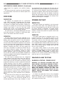
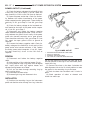
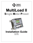
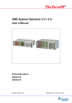
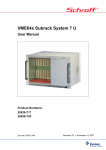
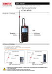
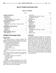
RS
8W-97 POWER DISTRIBUTION SYSTEM
8W - 97 - 1
8W-97 POWER DISTRIBUTION SYSTEM
TABLE OF CONTENTS
page
POWER DISTRIBUTION SYSTEM
DESCRIPTION . . . . . . . . . . . . . . . .
OPERATION . . . . . . . . . . . . . . . . . .
SPECIAL TOOLS
POWER DISTRIBUTION SYSTEMS
INTEGRATED POWER MODULE
DESCRIPTION . . . . . . . . . . . . . . . .
OPERATION . . . . . . . . . . . . . . . . . .
REMOVAL
...................
INSTALLATION . . . . . . . . . . . . . . . .
..........1
..........1
.........1
.
.
.
.
.
.
.
.
.
.
.
.
.
.
.
.
.
.
.
.
.
.
.
.
.
.
.
.
.
.
.
.
.
.
.
.
.1
.2
.2
.2
page
IOD FUSE
DESCRIPTION . . . . . . . . . . . . . . . . . . . . . . .
OPERATION . . . . . . . . . . . . . . . . . . . . . . . . .
POWER OUTLET
DESCRIPTION . . . . . . . . . . . . . . . . . . . . . . .
OPERATION . . . . . . . . . . . . . . . . . . . . . . . . .
DIAGNOSIS AND TESTING
DIAGNOSIS & TESTING - POWER OUTLET
REMOVAL
..........................
INSTALLATION . . . . . . . . . . . . . . . . . . . . . . .
...3
...3
...3
...3
..3
...4
...4
POWER DISTRIBUTION
SYSTEM
electrical current needed to operate many accessories
that the vehicle owner may choose to have installed.
DESCRIPTION
SPECIAL TOOLS
The power distribution system for this vehicle consists of the following components:
• Integrated Power Module (IPM)
• Front Control Module (FCM)
• Power Outlets
Refer to Wiring Diagrams for complete circuit schematics.
The power distribution system also incorporates
various types of circuit control and protection features, including:
• Automatic resetting circuit breakers
• Blade-type fuses
• Bus bars
• Cartridge fuses
• Circuit splice blocks
• Flashers
• Fusible links
• Relays
OPERATION
The power distribution system for this vehicle is
designed to provide safe, reliable, and centralized distribution points for the electrical current required to
operate all of the many standard and optional factory-installed electrical and electronic powertrain,
chassis, safety, security, comfort and convenience systems. At the same time, the power distribution system was designed to provide ready access to these
electrical distribution points for the vehicle technician to use when conducting diagnosis and repair of
faulty circuits. The power distribution system can
also prove useful for the sourcing of additional electrical circuits that may be required to provide the
POWER DISTRIBUTION SYSTEMS
Terminal Pick Kit 6680
INTEGRATED POWER MODULE
DESCRIPTION
The Integrated Power Module (IPM) is a combination of the Power Distribution Center (PDC) and the
Front Control Module (FCM). The IPM is located in
the engine compartment, next to the battery. (Fig. 1).
The PDC mates directly with the FCM to form the
IPM. The PDC is a printed circuit board based module that contains fuses and relays, while the FCM
contains the electronics controlling the IPM and
other functions. This IPM connects directly to the
battery positive through a four pin connector. The
ground connection is through two other connectors.
8W - 97 - 2
8W-97 POWER DISTRIBUTION SYSTEM
RS
INTEGRATED POWER MODULE (Continued)
Fig. 2 INTEGRATED POWER MODULE
Fig. 1 INTEGRATED POWER MODULE
1 - BATTERY THERMAL GUARD
2 - INTEGRATED POWER MODULE
3 - FRONT CONTROL MODULE
The IPM provides the primary means of voltage distribution and protection for the entire vehicle.
OPERATION
All of the current from the battery and the generator output enters the Integrated Power Module
(IPM) through a four- pin connector on the bottom of
the module. Internal connections of all of the power
distribution center circuits is accomplished by a combination of bus bars and a printed circuit board.
REMOVAL
(1) Disconnect the negative and positive battery
cables.
(2) Remove the battery thermal guard.
(3) Remove the battery (Refer to 8 - ELECTRICAL/BATTERY SYSTEM/BATTERY - REMOVAL).
(4) Using a flat-bladed screwdriver, twist the Integrated Power Module (IPM) bracket retaining latch
outward to free the IPM from its mounting bracket
(Fig. 2).
(5) Rotate the IPM counter-clockwise to access and
disconnect the electrical connectors (Fig. 3).
(6) Remove the IPM bracket clips from the hinge.
INSTALLATION
(1) Snap the left side of the Integrated Power Module (IPM) housing in its mounting bracket and connect the various electrical connectors.
Fig. 3 DISCONNECTING IPM
1 - INTEGRATED POWER MODULE
NOTE: Ensure that the Connector Positive Assurance (CPA) on the five-pin B+ connector is positively engaged to prevent generating a Diagnostic
Trouble Code (DTC).
(2) Rotate the IPM clock-wise until secured in
mounting bracket. An audible click may be heard.
(3) Install the battery (Refer to 8 - ELECTRICAL/
BATTERY SYSTEM/BATTERY - INSTALLATION).
(4) Install the battery thermal guard.
RS
8W-97 POWER DISTRIBUTION SYSTEM
8W - 97 - 3
INTEGRATED POWER MODULE (Continued)
(5) Connect the negative and positive battery
cables.
(6) Using a scan tool, check for any stored diagnostic trouble codes. Ensure that all vehicle options are
operational.
IOD FUSE
DESCRIPTION
All vehicles are equipped with an Ignition-Off
Draw (IOD) fuse that is removed from its normal
cavity in the Integrated Power Module (IPM) when
the vehicle is shipped from the factory. Dealer personnel are to remove the IOD fuse from the storage
location and install it into the IPM fuse cavity
marked IOD as part of the preparation procedures
performed just prior to new vehicle delivery.
The IOD fuse is a 20 ampere blade-type mini fuse
and, when removed, it is stored in a fuse cavity adjacent to the washer fuse within the IPM.
OPERATION
The term ignition-off draw (IOD) identifies a normal condition where power is being drained from the
battery with the ignition switch in the Off position.
The IOD fuse feeds the memory and sleep mode functions for some of the electronic modules in the vehicle
as well as various other accessories that require battery current when the ignition switch is in the Off
position, including the clock. The only reason the
IOD fuse is removed is to reduce the normal IOD of
the vehicle electrical system during new vehicle
transportation and pre-delivery storage to reduce
battery depletion, while still allowing vehicle operation so that the vehicle can be loaded, unloaded and
moved as needed by both vehicle transportation company and dealer personnel.
The IOD fuse is removed from the Integrated
Power Module (IPM) fuse cavity when the vehicle is
shipped from the assembly plant. Dealer personnel
must install the IOD fuse when the vehicle is being
prepared for delivery in order to restore full electrical
system operation. Once the vehicle is prepared for
delivery, the IOD function of this fuse becomes transparent and the fuse that has been assigned the IOD
designation becomes only another Fused B(+) circuit
fuse. The IOD fuse serves no useful purpose to the
dealer technician in the service or diagnosis of any
vehicle system or condition, other than the same purpose as that of any other standard circuit protection
device.
The IOD fuse can be used by the vehicle owner as
a convenient means of reducing battery depletion
when a vehicle is to be stored for periods not to
exceed approximately thirty days. However, it must
be remembered that removing the IOD fuse will not
eliminate IOD, but only reduce this normal condition.
If a vehicle will be stored for more than thirty days,
the battery negative cable should be disconnected to
eliminate normal IOD; and, the battery should be
tested and recharged at regular intervals during the
vehicle storage period to prevent the battery from
becoming discharged or damaged.
POWER OUTLET
DESCRIPTION
Two power outlets are installed in the instrument
panel center lower bezel. Two additional power outlets are incorporated into the left rear C-pillar and
the center console (if equipped). The power outlets
bases are secured by a snap fit. A hinged plug flips
closed to conceal and protect the power outlet base
when not in use.
OPERATION
The power outlet base or receptacle shell is connected to ground, and an insulated contact in the
bottom of the shell is connected to battery current.
The power outlet on the instrument panel marked
with a battery receives battery voltage from a fuse in
the Integrated Power Module (IPM) at all times. The
other power outlet on the instrument panel marked
with a key receives battery voltage only when the
key is in the on position.
The power outlet located in the center console
receives battery voltage all the time when positioned
between the front seats and key-on voltage when
positioned between the rear seats. The power outlet
located on the C-pillar receives battery voltage only
when the key is in the ON position.
DIAGNOSIS AND TESTING
DIAGNOSIS & TESTING - POWER OUTLET
WARNING: ON VEHICLES EQUIPPED WITH AIRBAGS, REFER TO RESTRAINTS BEFORE ATTEMPTING ANY STEERING WHEEL, STEERING COLUMN,
SEAT OR INSTRUMENT PANEL COMPONENT DIAGNOSIS OR SERVICE. FAILURE TO TAKE THE
PROPER PRECAUTIONS COULD RESULT IN ACCIDENTAL AIRBAG DEPLOYMENT AND POSSIBLE
PERSONAL INJURY.
(1) Check the fused B(+) fuse in the Integrated
Power Module (IPM). If OK, go to Step 2. If not OK,
repair the shorted circuit or component as required
and replace the faulty fuse.
8W - 97 - 4
8W-97 POWER DISTRIBUTION SYSTEM
RS
POWER OUTLET (Continued)
(2) Check for battery voltage at the fused B(+) fuse
in the IPM. If OK, go to Step 3. If not OK, repair the
open fused B(+) circuit to the IPM fuse as required.
(3) Open the power outlet door. Check for continuity between the inside circumference of the power
outlet receptacle and a good ground. There should be
continuity. If OK, go to Step 4. If not OK, go to Step
5.
(4) Check for battery voltage at the insulated contact located at the back of the power outlet receptacle. If not OK, go to Step 5.
(5) Disconnect and isolate the battery negative
cable. Remove the appropriate bezel. Check for continuity between the ground circuit cavity of the power
outlet wire harness connector and a good ground.
There should be continuity. If OK, go to Step 6. If not
OK, repair the open ground circuit to ground as
required.
(6) Connect the battery negative cable. Check for
battery voltage at the fused B(+) circuit cavity of the
power outlet wire harness connector. If OK, replace
the faulty power outlet receptacle. If not OK, repair
the open fused B(+) circuit to the IPM fuse as
required.
REMOVAL
(1) Disconnect and isolate the battery negative
cable.
(2) Note position of the retaining bosses (Fig. 4).
(3) Using external snap ring pliers with 90 degree
tips. Insert pliers with tips against bosses and
squeeze forcing bosses out of base.
(4) Pull out the base through mounting ring by
gently rocking pliers.
(5) Disconnect the base wires.
(6) Remove light ring and disconnect wire.
INSTALLATION
(1) Position the mounting ring on the instrument
panel and feed the wires through the ring. Index the
Fig. 4 POWER OUTLET
1
2
3
4
-
RETAINING BOSSES-ENGAGE PLIERS HERE
PARTIALLY REMOVED
EXTERNAL SNAP-RING PLIERS
PULL BASE OUT-THROUGH MOUNTING RING
cap and the mounting ring with the index tab at the
9 o’clock position to the key in the instrument panel.
Install the ring.
(2) Connect the wires to the base. Orientate the
base alignment rib at the 11 o’clock position to mate
the groove in the mounting ring to the base.
(3) Push the base into the bezel until it locks in
place.
(4) Check operation of outlet or element and
install the outlet cap.