1
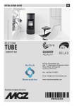
IN-ECO RING BLOWER
INW
ring blower / vacuum pump, single-stage and two-stage, with side channel
USER MANUAL
(version 2012.01)
Thank you for purchasing the INW series ring blower / vacuum pump.
Read this manual carefully before using the product.
INW blowers/pumps comply with the conditions of European Union directive 2002/95/ES issued by the European
Parliament and Commission dated January 27, 2003 on
the Restriction of the use of certain Hazardous Substances
in electrical and electronic equipment.
INW blowers/pumps comply with the European Community directive for mechanical equipment.
IN-ECO, spol. s r.o.
IN-ECO RING BLOWER - User manual
Version 2012.01
CONTENTS
IN-ECO RING BLOWER ............................................................................................. 1
INW ............................................................................................................................. 1
User manual ...................................................................................................................... 1
CONTENTS .........................................................................................................................2
1 Definitions .............................................................................................................. 3
1.1 General .................................................................................................................... 3
1.2 Description of INW blowers/pumps .......................................................................... 3
2 Safety .................................................................................................................... 4
3 Use ........................................................................................................................ 5
3.1 General .................................................................................................................... 5
3.2 Conditions of use ..................................................................................................... 5
3.3 Temperature of discharge gases ............................................................................. 6
4 Installation ............................................................................................................. 7
4.1 Handling, moving, transporting ................................................................................ 7
4.2 Assembly ................................................................................................................. 7
4.3 Installation................................................................................................................ 8
5 Operation ............................................................................................................... 8
5.1 Start-up .................................................................................................................... 8
5.2 Operation ................................................................................................................. 9
6 Maintenance .......................................................................................................... 9
6.1 Inspection ................................................................................................................ 9
6.2 Maintenance ............................................................................................................ 9
6.3 Storage .................................................................................................................... 9
7 Service................................................................................................................. 10
8 Accessories ......................................................................................................... 10
8.1 Air filter................................................................................................................... 10
8.2 Safety valve ........................................................................................................... 10
8.3 Manometer............................................................................................................. 10
8.4 Backflow valve ....................................................................................................... 10
Recommended installation of the INW blower/pump with accessories:........................... 10
9 Waste disposal .................................................................................................... 11
10 Warranty .............................................................................................................. 11
For current information about the company and its products, visit www.in-eco.eu.
[email protected]
2
www.in-eco.eu
IN-ECO, spol. s r.o.
IN-ECO RING BLOWER - User manual
Version 2012.01
1 DEFINITIONS
1.1
GENERAL
Manual
This user manual is the intellectual property of IN-ECO, spol. s.r.o. All rights are reserved. The current version
of the manual is available at www.in-eco.eu.
Equipment
Within the scope of this manual, equipment or electrical equipment is considered the ring blower or vacuum
pump with a side channel.
INW ring blower / vacuum pump
An INW ring blower / vacuum pump is any blower or pump with a INW type side channel, either single-stage
or multi-stage. Whether the equipment operates as a blower or pump depends on the connection to the
system.
Gas
Within the scope of this manual, gas is considered as pure gas or a mixture of gases. In practice, this is usually air.
Authorized IN-ECO service
Within the scope of this manual, authorized IN-ECO service is considered the service center of IN-ECO, spol.
s.r.o. For more details (contact information), visit www.in-eco.eu.
1.2
Fig.1:
DESCRIPTION OF INW BLOWERS/PUMPS
Assembled INW blowers/pumps
A:
single stage models
(INW, INW HP)
B:
1 > Compressor chamber
2 > Front cover of blower chamber
3 > Suction branch with silencer
4 > Discharge branch with silencer
5 > Assembly base
6 > Arrow indicating the direction of the gas flow
7 > Arrow indicating the direction of rotation of the rotor
[email protected]
3
double stage models
(INW)
C:
high pressure models
2-stage (INW HP)
8 > Driving motor
9 > Ventilator cover
10 > Terminal box
11 > Cooling air conducting plate
12 > Suction/discharge branch flange
13 > Lifting loop
www.in-eco.eu
IN-ECO, spol. s r.o.
IN-ECO RING BLOWER - User manual
Version 2012.01
2 SAFETY
Handling the equipment in an unprofessional manner may lead to heavy or even fatal injuries!
Read this manual carefully before performing any operations with the INW ring blower/ vacuum pump. The
manual must be absolutely clear. Follow all instructions in this manual and keep it in a visible place near the
operated equipment.
The equipment shall only be operated by persons trained to operate it according to this manual and relevant
safety regulations.
Personal protective equipment shall be used for all work carried out using the equipment. Do not wear your
hair loose or wide, loose clothing.
The equipment must be fully assembled before start-up. Check the following thoroughly: terminal box cover,
silencers on the suction and discharge branches and ventilator cover. Do not tamper with the equipment
frame. Do not dismantle cover caps or any other structural elements (besides the lifting loop).
Do not remove stickers containing warning and safety information from the equipment.
Risk of electric shock!
Only a qualified electrician can work on the electrical equipment and must observe all relevant standards
while doing so.
Prior to starting work on the electrical equipment:
> disconnect the power supply,
> ensure the equipment cannot be switched on again,
> check that the power supply is disconnected,
> cover or enclose neighboring live parts.
Open the terminal box cover only after you have checked that the power supply has been disconnected.
Risk of injury caused by overpressure or underpressure!
Check pipes, joining and anchoring elements, and valves on a regular basis.
Protect yourself against:
> sudden heavy gas leaks,
> hair or clothing being suddenly caught.
Risk of injury caused by rotating parts (external ventilator, rotor, shaft)
The moving rotor is accessible when the suction and discharge branches are open! Do not reach into the
equipment through open branches! Do not insert any objects into the equipment through open branches! Prevent access to the rotor via suction and discharge branches! Let the rotor come to a complete stop after stopping the equipment.
The external ventilator cover contains holes in which hair or loose clothing can become caught.
Protect yourself against:
> cuts, amputated limbs,
> hair or clothing getting caught
Risk of injury caused by a gas leak!
Check pipes, joining and anchoring elements, and valves on a regular basis.
Protect yourself against:
[email protected]
4
www.in-eco.eu
IN-ECO, spol. s r.o.
IN-ECO RING BLOWER - User manual
Version 2012.01
> injuries due to compressed/discharged gas leaks (burns).
Risk of injury caused by hot surface and hot medium!
the INW ring blower/ vacuum pump can be very hot. The surface temperature of the warmed-up equipment
can exceed 70°C, and in some cases even reach 160°C.
To prevent burns, do not touch the surface of the equipment during operation. Allow the equipment to cool
down after stopping.
If necessary, install suitable protection preventing random contact with the hot equipment (protective mesh,
perforated plate, etc.).
The compressed medium can be very hot.
Protect yourself against:
> direct contact with the hot equipment or pipe,
> injuries due to compressed/sucked gas leaks (burns).
Risk of injury caused by falling or overturned loads!
Observe the safety regulations when operating the equipment and transporting the equipment. Use personal
protective equipment. Secure the equipment against unwanted movement, overturning, falling. Do not stand
under lifted loads!
Noise emission
The maximum levels of acoustical noise, or the sound power level respectively, measured according to the
conditions of the relevant standard, are stated for each piece of equipment at www.in-eco.eu. However, after
installing the equipment, the total noise level in the workplace can exceed 85 dB. In this case:
> designate the zone with an increased noise level,
> use hearing protection.
USE
2.1
GENERAL
This manual applies to the INW ring blower/ vacuum pump with a side channel, single-stage and multi-stage,
with a single-phase and three-phase motor. It contains safety information, and instructions for handling,
transporting, installation, start-up, operating, maintenance, storage and disposal. The manual must be available at the location in which the equipment is used.
INW the INW ring blower / vacuum pump are used for producing overpressure/vacuum. For specific technical
parameters, visit www.in-eco.eu, some of which can also be seen on the equipment label. The technical parameters of the equipment, namely the maximum pressure difference and suction power, stated on the
www.in-eco.eu website and on the label are valid under the following conditions (nominal values):
> ambient temperature: 25°C,
> temperature of gases sucked in: 15°C,
> gas pressure for a blower on the suction branch and for a pump on the discharge branch: 1013 mbar
(abs).
2.2
CONDITIONS OF USE
Purpose
The INW ring blower / vacuum pump are used for compressing or pumping gases, which are not explosive,
flammable, aggressive or poisonous.
The INW ring blower/ vacuum pump are designated for continuous operation. Maximum number of starts per
hour: 10.
[email protected]
5
www.in-eco.eu
IN-ECO, spol. s r.o.
IN-ECO RING BLOWER - User manual
Version 2012.01
the INW ring blower / vacuum pump only according to the conditions specified by its parameters, which are
alsoavailable at www.in-eco.eu. This particularly concerns the ambient temperature and the sucked gas,
maximum pressure difference and level of electrical coverage.
Placement
Place the equipment in a well-ventilated area with sufficient air circulation. For outdoor use, place the equipment under a shelter, protecting it against unfavorable weather conditions (rain, snow, direct sunlight, etc.).
Prevent any liquids from entering the equipment. If the pipe to which the equipment is connected discharges
into liquid, place the equipment above the level of this liquid. If the equipment must be placed below this level,
prevent the reverse suction of liquid (for example, install a siphon on the pipe, install a backflow valve, etc.).
If the equipment (blower) is used in water treatment plant operation, place it accordingly to prevent it from
drawing in vapors from the water treatment plant, or from sucking in sludge or sludge foam.
Install the equipment in areas with sufficient space to enable its regular maintenance and necessary repairs.
The improper placement or installation can have a negative effect on the service life of the equipment.
Ventilation, cooling
Ventilation and cooling is essential for the proper operation of the equipment. Leave at least 20 cm around
equipment placed indoors for natural cooling. When installing on a vertical wall, install the equipment at least
20 cm above the floor.
If necessary (for example, if you use the equipment in a small area or within a soundproof housing), ensure
the necessary air circulation (e.g. using a ventilator).
Air (gas) temperature and humidity
The INW ring blower / vacuum pump are designated for use in ambient temperatures ranging from -30°C to
+40°C. The optimal ambient operating temperature is 0°C to 25°C. When used in an environment with a temperature exceeding 25°C, you must consider that the maximum pressure difference will be lower. About 10%
for a temperature of 40°C.
The maximum temperature of gas drawn in must not exceed 40°C.
The maximum humidity of gas drawn in must not exceed 80%.
Altitude
Air pressure (and humidity) drops with increasing altitude. According to the laws of physics, this affects the
blower/pump performance. If you intend to use the equipment at an altitude exceeding 1,000 meters above
sea level, consult the consequences with an authorized IN-ECO service center.
! Restrictions !
Do not use INW ring blowers / vacuum pumps for taking in steam, or gas that contains a high volume of dust,
charged particles, cellulose and particles larger than 40 μm.
Do not use INW ring blowers / vacuum pumps for compressing or pumping gases, which are explosive, flammable, aggressive or poisonous.
Do not use INW ring blowers / vacuum pumps in areas where explosive gases may emerge.
Do not use INW ring blowers / vacuum pumps for taking in water or other liquids. Prevent any liquids from
entering INW blowers/pumps.
2.3
TEMPERATURE OF DISCHARGE GASES
The compression of gas results in an increase in temperature. Temperature increases depending on the
pressure difference differ with each type of equipment. The curves of this dependency are available at
www.in-eco.eu. The following tables provide orientation values, separately for ring blowers and vacuum
pumps:
[email protected]
6
www.in-eco.eu
IN-ECO, spol. s r.o.
IN-ECO RING BLOWER - User manual
Version 2012.01
Tab. 1: Temperature increase depending on pressure difference – ring blowers with side channel:
Pressure difference
Single-stage
Double-stage
High pressure
∆p
[mbar]
∆ T [K]
∆ T [K]
∆ T [K]
100
200
300
400
500
600
700
15-20
30-55
50-80
70-110
90-100
15-20
25-40
40-60
55-100
75-110
80-120
90-120
15-20
25-35
35-40
45-55
55-70
65-90
80-115
Tab. 2: Temperature increase depending on pressure difference – vacuum pumps with side channel:
Pressure difference
Single-stage
Double-stage
High pressure
∆p
[mbar]
∆ T [K]
∆ T [K]
∆ T [K]
100
200
300
400
500
15-22
35-60
80-90
90-120
15-20
35-50
55-85
90-115
90-120
15-20
30-40
45-50
60-80
80-100
600
700
95-120
125
CAUTION
Protect the original product label of the equipment. It contains important information for the proper use,
maintenance and service of the equipment. All warranty rights are voided by damaging or removing this label.
3 INSTALLATION
3.1
HANDLING, MOVING, TRANSPORTING
Use sufficient personal protective equipment when handling the equipment. The equipment may have sharp
edges. Equipment weighing 30 kg or more includes lifting loops (screwed). Use adequate lifting and handling
equipment (pulleys, cranes, etc.). When moving and transporting the equipment, make sure the equipment is
sufficiently anchored to avoid unwanted movement, overturning or falling. Incorrectly moving the equipment
may lead to damage to property or health.
Do not stand under lifted loads!
3.2
ASSEMBLY
Due to better packaging, some INW ring blower / vacuum pump models (2- and 3-stage) include a dismantled
suction or discharge branch with integrated silenced (hereinafter referred to as a branch). Single-stage ring
blower / vacuum pump models are usually supplied completely assembled.
Fig.2:
Correctly assembled INW blower/pump
A: INW double stage models
B: INW high pressure models
C: INW high pressure models single stage
1 > Branch with silencer (supplied dismantled)
3 > Branch with silencer assembled by the manufacturer
2 > Branch assembly location (non-covered hole) 4 > Cover caps
[email protected]
7
www.in-eco.eu
IN-ECO, spol. s r.o.
IN-ECO RING BLOWER - User manual
Version 2012.01
Differences: Depending on the model, besides the branch, the flange between the compression chamber and
the branch itself can be dismantled. Some models can also have joining (internal) threading on an independent flange, which is then mounted to the free branch end.
Branch assembly (valid only for models supplied with dismantled branch):
Unpack the supplied branch with seals and screws, or flanges. If the flange is also dismantled, assemble it
onto the non-covered hole 〈2〉 first. Use the provided screws to attach the dismantled branch 〈1〉 to the flange
(non-covered). Apply the relevant seals during assembly. Do not remove the branch 〈3〉 supplied by the manufacturer. Do not remove any potential cover caps 〈4〉. Other connections are not permitted. If you are uncertain about anything, contact the authorized IN-ECO service center.
Branches have plastic covers to prevent foreign objects from penetrating the blower. Remove covers directly
before connecting the pipe or hose. Keep them for future use, for example, during maintenance. Branches
have an internal thread, the dimensions of which are available at www.in-eco.eu.
3.3
INSTALLATION
Mechanical
Install the equipment on a solid foundation or solid base. The equipment can be installed either horizontally or
vertically (according to the orientation of the base). Use binding material with sufficient solidity to anchor the
equipment to the base and secure to avoid spontaneous loosening. The lifting loop can be dismantled after
installation.
Electrical
Only a qualified electrician can work on the electrical equipment and all relevant standards must be observed
while doing so.Connect the INW blower/pump to a power supply according to the specifications stated in the
catalog sheets also available on the www.in-eco.eu website. The equipment is supplied without connecting
electric wires. Use electrical wires of the proper strength (section) according to the electrical specifications for
the specific blower/pump stated in the catalog sheets on the www.in-eco.eu website. The wiring diagram is on
the cover of the terminal box. First, connect the grounding wire correctly. Make sure to protect against short
circuits and equipment overloading. Install a protective motor switch (motor circuit-breaker) to protect the motor against overloading. Set the switch to the nominal current stated on the equipment label. We recommend
using motor circuit-breakers, which switch the motor off with a certain time delay, with respect to potential
short-term excess current. Current greater than the nominal current can flow through the equipment for a
short period du-ring a cold start.
Check the wiring connection before permanently connecting the equipment.
Start the equipment for a short period and compare the direction of rotation with the direction indicated on the
motor ventilator cover. If necessary, change the wiring connection until the direction of the rotor rotation is the
same as the direction shown by the arrow on the motor ventilator cover. You can see the actual direction of
rotation when stopping the equipment and viewing the motor ventilator through the screen on the cover.
Pipes
The connection pipes should be 1.5 times the dimension of the equipment branch. The
system pressure resistance (pressure losses) is increased for pipes that are excessively
narrow or long. This increases the demands on the gas (air) source and also increases
power consumption. Choose a material for the pipe that can withstand a gas temperature that can be achieved during operation (compression). In some cases, the difference
in gas (air) temperatures can exceed 100°C (section 3.3. Temperature of discharge gases).
Fig. 3: Pipes
4 OPERATION
4.1
START-UP
Check the following prior to the equipment start-up:
> the complete and proper assembly of the blower/pump,
> electrical wiring,
> tightness of all connected pipes, or hoses,
> opened close valves on the suction or discharge pipes,
[email protected]
8
www.in-eco.eu
IN-ECO, spol. s r.o.
IN-ECO RING BLOWER - User manual
Version 2012.01
> correct direction of the gas flow, or direction of the rotor rotation.
The air flow direction is indicated on the suction or discharge branch.
4.2
OPERATION
INW ring blowers / vacuum pumps are designated for continuous operation. Observe the operating conditions
stated in this manual, particularly section 2 Safety, with emphasis on ambient temperature and gas drawn in.
For interrupted operation, do not exceed the maximum number of starts per hour, which the manufacturer has
determined as 10.
Prevent any liquids or solid objects from entering the equipment. Use an air filter with a permeability less than
40 μm.
The maximum possible pressure difference in the system must not be greater than the maximum pressure
difference of the equipment stated in the catalog sheet on the www.in-eco.eu website or on the product label.
Otherwise the equipment is critically overloaded. The common operating pressure in the system should be at
least 10% lower than the maximum working pressure on the product label or catalog sheet of the equipment.
5 MAINTENANCE
5.1
INSPECTION
Check the INW blower/pump and associated pipes, gas (air) distribution system on a regular basis. In particular, inspect the temperature of the equipment and gas drawn in, as well as the gas pressure in the pipes.
Check the setting of dust and remove dust which could limit ventilation or cooling.
Operated electrical equipment should be checked and inspected by a qualified employee on a regular basis,
at the latest within the terms specified by the relevant standard.
If you encounter any unexpected noise or rough motor operation, disconnect the equipment from the power
supply and check its state. Repairs shall be given to authorized IN-ECO service centers.
5.2
MAINTENANCE
Disconnect the equipment from the power supply to avoid electric shock. Ensure the equipment will not repeatedly start upon reconnection to the power supply. Do not perform maintenance work if the equipment is
heated up to operating temperature.
Check and replace the following regularly:
> air filter in the intervals specified by the supplier,
> bearings* in the equipment.
*) The minimum service life of bearings is 15,000 operating hours, providing the operating conditions are
respected. The replacement of bearings shall be given to authorized IN-ECO service centers. Keep the report
from the bearings replacement.
When disconnecting the equipment from the pipes, close the suction and discharge branch with a plastic cover, which was supplied or in some other manner. During maintenance, prevent any objects from entering the
blower or pipes.
After maintenance, or repair, prior to start-up, proceed according to the instructions in section 5.1 Start-up.
5.3
STORAGE
Keep the INW blowers/pumps in a dry environment with normal air humidity. For a relative humidity of 80% or
higher, store in a closed package with a drying agent.
[email protected]
9
www.in-eco.eu
IN-ECO, spol. s r.o.
IN-ECO RING BLOWER - User manual
Version 2012.01
6 SERVICE
Repairs shall only be carried out by an authorized IN-ECO service center during the warranty period. All warranty rights are forfeited if the equipment is tampered with during the warranty period. Have an authorized INECO service center service INW ring blowers / vacuum pumps after the warranty has expired.
ACCESSORIES
Use original accessories with INW blowers/pumps with side channel. Contact the authorized IN-ECO service
center for the specifications and supplies of accessories (for example: air filters, safety valves, manometers,
backflow valves, flowmeters).
6.1
AIR FILTER
The air filter should be installed as close to the suction branch as possible to protect the equipment against
solid objects, dust, cellulose, etc. Do not start the equipment without an air filter. The filter should not let particles larger than 40 μm through. Use a filter with sufficient capacity so the pressure loss is adequate.
Original air filter
The air filter (filtration insert) must be cleaned no later than after 250 operating hours and the filtration insert replaced no
later than after 3,000 operating hours. The authorized IN-ECO service center will supply the filtration insert.
Removal:
a) blower filter / unscrew the wing nut. Remove the protective cover and take out the filtration insert.
b) pump filter / release the closing pins of the filter lid. Remove the filter lid and take out the filtration insert.
Clean the filtration insert (blow and manually dust) and replace if necessary.
Assembly: in reverse order.
The filtration insert of the air filter must be cleaned or replaced more frequently depending on the level of medium impurity. Performance becomes impaired with insufficient maintenance of the air filter and with it the service lift is shortened.
6.2
SAFETY VALVE
Install a safety valve to prevent from overloading the equipment and subsequently shortening its service life.
The safety valve must be configured for the maximum working pressure. This way the equipment will be protected against overloading. (The maximum working pressure is usually 7-15% lower than the maximum pressure stated on the product label.)
6.3
MANOMETER
Install a manometer for the purpose of fundamental pressure ratio diagnostics.
6.4
BACKFLOW VALVE
A backflow valve can be installed to increase the protection of the equipment against the reverse suction of
liquid into the equipment.
RECOMMENDED INSTALLATION OF THE INW RING BLOWER / VACUUM PUMP WITH ACCESSORIES:
The diagram of the recommended (single-stage) INW blower/pump with accessories is shown on figures:
1
2
3
4
5
Blower/pump
Air filter
Manometer
Safety valve
Backflow valve
Fig. 4: Blower with accessories
[email protected]
Fig. 5: Pump with accessories
10
www.in-eco.eu
IN-ECO, spol. s r.o.
IN-ECO RING BLOWER - User manual
Version 2012.01
7 WASTE DISPOSAL
Valid waste management legal regulations must be observed for proper waste disposal.
WARRANTY
Providing the warranty conditions are respected, IN-ECO provides a 2 year warranty on INW ring blowers /
vacuum pumps.
Warranty conditions
> The equipment must be used (installed and operated) in accordance with this manual.
> Repairs shall only be carried out by an authorized IN-ECO service center during the warranty period.
> All warranty rights are forfeited if the equipment is tampered with during the warranty period.
The following must be included when returning the INW ring blower/ vacuum pump:
1. sales receipt (warranty),
2. description of how the equipment is used and the issue,
3. contact information: address, phone number, e-mail, etc.
Equipment returned or submitted for repair must be delivered clean.
Costs on transporting the equipment to the authorized IN-ECO service center and back to the customer are
covered by the customer.
The warranty expires:
> if the conditions of installation and equipment operation are not observed,
> if the required maintenance is not respected,
> if the warranty conditions are not respected,
THANK YOU
Thank you for purchasing the INW series ring blower / vacuum pump. We hope you will be satisfied. Do not
hesitate to contact us if you have any questions.
[email protected]
11
www.in-eco.eu