1
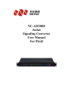
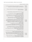
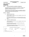
IPPBX
/
VOICE GATEWAY
NC-MG320
User Manual
Version 2.4
NC-MG320 Manual
Foreword
The purpose of this manual is to supply operating, set up and configure with the
information needed to properly and quickly set up and configure the NiceUC's NC-MG320.
We had made every effort to ensure that the information in this manual is accurate
and adequate.
If you use this manual when you encounter any problems and have any good
suggestions , please contact us:
ShenZhen NiceUC communication Tech Co., Ltd
Room 1401, YiZhe Building, YuQuan Rd, NanShan District,
ShenZhen City, GuangDong , China
Tel:86-755-26722761
Fax:86-755-26526970
Email: [email protected]
[email protected]
Website: http://www.nicecomm.com.cn
http://www.niceuc.com
2
NC-MG320 Manual
Contents
Foreword..................................................................................................................................2
Contents...................................................................................................................................3
Chapter 1 Overview........................................................................................................... 5
1.1 Product description......................................................................................................... 5
1.1.1 Brief introduction.................................................................................................. 5
1.1.2 Main Features........................................................................................................ 5
1.1.3 The detailed configuration of this series................................................................7
1.2 Hardware Appearance.....................................................................................................7
1.2.1 Hardware structure.................................................................................................7
Chapter 2 Install....................................................................................................................9
2.1 Accessories (Cables) of NC-MG320.............................................................................. 9
2.1.1 Connector type.....................................................................................................10
2.2 Way of connection........................................................................................................ 11
Chapter 3 Console connect................................................................................................. 11
3.1 Setup a HyperTerminal at windows system..................................................................11
3.2 Message from HyperTerminal...................................................................................... 14
3.3 Important messages can be modified............................................................................15
3.4 Modify the equipment parameter through console....................................................... 15
3.4.1 Modify parameter when boot pause.....................................................................15
3.4.1.1 The way to modify the IP Address............................................................16
3.4.1.2 The way to modify the Netmask and Gateway......................................... 16
3.4.2 Modify parameter when boot finished....................................................................16
Chapter 4 Software Configuration -Guidance of using tool "PbxCconfig.exe"................. 17
4.1 Copy the software from CD to your local pc for using.................................................17
4.2 Window Interface of PbxConfig.exe............................................................................ 18
4.2.1 Connect with NC-MG320....................................................................................18
4.2.2 Disconnect NC-MG320....................................................................................... 19
4.2.3 Read Parameters.................................................................................................. 19
4.2.4 Write Parameters..................................................................................................19
4.2.5 Load Parameters.................................................................................................. 20
4.2.6 Save Parameters...................................................................................................20
4.2.7 Reboot (Reset) Equipment...................................................................................20
4.3 SysPart (System Parameter)......................................................................................... 21
4.3.1 Rules (Call Control).............................................................................................23
4.3.1.1 Length Rules.............................................................................................24
4.3.1.2 Convert Rule.............................................................................................25
4.3.1.3 Router Rule...............................................................................................26
4.3.2 Login User........................................................................................................... 31
4.3.3 Access Limit........................................................................................................ 32
4.4 Instructions for configuration of Pcm (in LinePart)..................................................... 33
4.4.1 Configuration of PCM......................................................................................... 33
4.4.1.2 SS7 Link (Configuration of SS7)..............................................................34
3
NC-MG320 Manual
4.4.1.3 Configuration of ISDN PRI...................................................................... 37
4.4.1.4 Configuration of V5.2...............................................................................38
4.4.1.5 Configuration of CAS/R2/EM.................................................................. 40
4.4.2 Virtual Caller....................................................................................................... 41
4.4.2.1 Virtual Caller.............................................................................................41
4.4.2.2 PCM * Application Set for virtual caller.................................................. 41
4.4.3 Number Plan for SS7 (Modify attribute of number under SS7).......................... 42
4.4.4 Number Plan for PRI (Modify attribute of number under PRI)...........................44
4.5 SLC (Configuration of analog line).......................................................................... 47
4.5.1 Settings of Line Type...........................................................................................47
4.5.2 Settings of Analog signal..................................................................................... 47
4.5.3 Settings of Calling detection................................................................................49
4.5.4 Setting of Line Volume........................................................................................ 49
4.6 Configuration of VoIP...................................................................................................50
4.6.1 VoIP Parameter.................................................................................................... 50
4.6.2 Register Parameter...............................................................................................54
4.6.3 Fax Parameter...................................................................................................... 55
4.6.4 VoIP User............................................................................................................. 56
4.7 Function configuration................................................................................................. 56
4.7.1 SIP-T....................................................................................................................57
4.7.2 Control for Ringback Tones.................................................................................57
Chapter 5 Debug Monitor...................................................................................................57
5.1 Initialization Information..............................................................................................57
5.2 Introduction for the command...................................................................................... 58
5.3 The software to monitor................................................................................................59
Appendix 1 Using wftpd.exe to load bin file.................................................................... 60
Appendix 2 Information for SS7 Signaling...................................................................... 63
4
NC-MG320 Manual
Chapter 1 Overview
1.1
Product description
1.1.1 Brief introduction
According to the demand of voice business from the enterprise/operator, NC-MG320 is a
IPPBX which independently R&D by NiceUC Communication. This product which locates at
the interface between PSTN and IP , achieve the conversion among FXO, FXS, E1 and VoIP
SIP,and achieve the transfer between remote extension, remote seating and the headquarter;
meanwhile complete the media stream transformation between the bearer channel of PSTN
and IP.
NC-MG320 uses advanced hardware and software technology and carrier-class design to
ensure the high reliability of equipment. The system of NC-MG320 uses the mature
high-performance CPU and DSP; and uses embedded real-time operating system and efficient
algorithm, so it has excellent properties. With modular design of inserting board, NC-MG320 is
expandable by your requirement.
1.1.2 Main Features
●Signaling:
·SS7 SS7(ITU-T Q.700 series), 24bits/14bits PC, ISUP/TUP
·ISDN-PRI(ITU-T Q.931,Q.921)
·V5.2(ITU-T G.964,G.965)
·CAS R2(Q.400-Q.490)
·CAS DTMF(BellCore TR-TSV-002275, Subsection 6.13)
●VoIP Protocol:
·SIP:
RFC3326(Reason header in SIP messages)
RFC3372(SIGTRAN and SIP-T)
RFC2327(sdp)
RFC3398(ISUP-SIP Mapping)
RFC3261(sip)
RFC5806(Diversion Indication in SIP)
RFC2833( DTMF )
RFC3362(t.38)
5
NC-MG320 Manual
RFC 3261(SIP 2.0)
RFC3204(MIME media types for ISUP and QSIG Objects)
RFC3578(Mapping of ISUP overlap to SIP)
·Codec:G.711u-Law and A-Law, G.711 Appendix 1, G.723.1 and G.723.1 Annex A, G.729
Annex A and Annex B, G.726, GSM,ARM,ILBC
●Ethernet support :
·TAG VLAN setting supported
· Auto-negotiation setting, rate setting, full/half duplex setting and flow-control setting
supported
·built-in dynamic Ethernet MAC address list (1024), local data frame filtration
·Auto-delete of faulted E1 links(LOS、AIS、LOF) and auto-restore when the malfunction
is gone
·Rate N×2.048Mbps,N=0~4 Duplex Full/Half auto-negotiation
·Physical connector RJ45 Comply with IEEE802.3
·MAC address table Capability 1024
·minimum frame length 64bytes
·maximum frame length 1916 bytes
·VLAN Default setting: closed Traffic control Default setting: open
●Main Business Function:
·As a terminal, support the register trunk function to other GK(Gatekeeper) or SIP Server.
· As a gateway, support the control from superior GK or SIP Server to complete the
trunking calls;
·As a IPPBX, support that other terminals register on it.
·Support any switch among E1, FXO, FXS, SIP;
·Support automatic routing function;
·Support high capacity of black and white lists;
·Simultaneously support the register of 4 SIP Server;
·Can support 1024 registered SIP Phones;
·Support output of CDR;
·Fax support T.30, T38 and pass through;
·64 conference;
·Voice recording;
6
NC-MG320 Manual
1.1.3 The detailed configuration of this series
Configuration Capacity
Physical Specification
Type/Name
Configuration Capacity
Name of interface
Quantity of interface
FXO/FXS
4 to 32
PCM
1 to 4
Registered
SIP Phone
E1/T1
32 to 1024
4 lines interface
(RJ45)
1 to 8
1 to 4
LAN
2
32 to 128
Console
1
T30/T.38
32
Power interface
1
Conference
64
Recording
120
Voice play
120
VOIP
Channel
1.2
Hardware Appearance
Physical Features:
Item
Specification
Input Voltage
110-240V AC
Full-load Power
30 W
Dimension
(W×D×H)
Weight
Environment
480mm*365mm*44mm (1U)
5 KGS
Temperature
0℃~50℃
Relative Humidity
Less than 80%
1.2.1 Hardware structure
NC-MG320 is standard 19 inch rack mounted equipment with 1 U height, dimension is
480mm×365mm×44mm. Please see following figure is the picture of NC-MG320.
It is modular design by inserting boards. Each set of NC-MG320 supports 1 CPU board, 1
7
NC-MG320 Manual
power supply and up to 2 user boards. The CPU board supports 1 to 4 E1; The user boards
are with analogue lines, each user boards is with up to 16 analogue lines (analogue lines can
be configured with all FXO or all FXS or the total of FXS and FXO), 2 user boards × 16
analogue lines/user board is 32 analogue lines, so each set of NC-MG320 supports up to 32
analogue lines (32 FXO or 32 FXS or the total of FXS and FXO is 32).
●The front panels show as follows: (Remark: This screenshot is from the NC-MG320 which is
with 220V AC power supply)
·"NiceUC's Logo and Model no": Logo of NiceUC and model no NC-MG320;
·"Console port": used for connecting console cable, the specification is RJ45 , usually the
specification of the other side is RS232;
·"Indicator lights of CPU boards": from left to right, they are as follows:
DATA O LINK 0 LINK 1 PCM 1 PCM 3 POWER
DATA 1 FE/GE FE/GE PCM 0 PCM 2
RUN
Make a brief introduction of the these indicator lights on the CPU board in the front panels:
Name of
indicators
Description
Normal
Abnormal
status
status
How to do
POWER
Power
on
off
Check the power supply
RUN
Run
on
off
Check the device is running or not
PCM 0
Operation of the 1st E1
off
on
PCM 1
Operation of the 2nd E1
off
on
PCM 2
Operation of the 3th E1
off
on
PCM 3
Operation of the 4th E1
off
on
LINK 0
Connection of network
on
off
Check the connection of network
LINK 1
Connection of network
on
off
Check the connection of network
FE/GE
100MB/1000MB Ethernet
on
off
Check the connection of network
Check the connection of E1/T1 cable
and the configuration of signaling
Check the connection of E1/T1 cable
and the configuration of signaling
Check the connection of E1/T1 cable
and the configuration of signaling
Check the connection of E1/T1 cable
and the configuration of signaling
DATA 0
DATA 1
8
NC-MG320 Manual
·"Indicator lights of Users": describe the status of each user. They are as follows:
1 3 5 7 9 11 13 15
POWER
2 4 6 8 10 12 14 16
The indicator lights from 1 to 16 describe the status of each user. The 1 indicates the status
of the 1st user, the 2 indicates the 2nd user, and so on. When the light is on, means that the user
is busy; when the light is off, means that the user is free or there is no operation of the user.
●The back panels show as follows:
·UC ports: for analogue users, each UC port supports 4 lines, there are total 8 UC ports, the
maxima analogue users is 32 lines (4*8=32);
·PCM Ports: for E1 or T1;
Chapter 2 Install
2.1 Accessories (Cables) of NC-MG320
Check the package to make sure no items are missed in the box, to start install and configure
MG320, you must have the below accessories ready at least: (All of these accessories are
enclosed with the device NC-MG320 when we delivery)
●A Standard PC with network adapter (supply by the customer)
●one Power Cable (-48 V DC or 110 to 220 V AC) (enclosed with MG320)
●E1 cable (The E1 cable that we provide is RJ45 to 2 BNC, if you want to DIY a E1 cable,
please see below wiring diagram); (enclosed with MG320)
PCM connector form RJ45 to BNC:
RJ45
1
2
4
5
Surface
Core
Surface
Core
BNC
RX
TX
9
NC-MG320 Manual
●A Console cable (enclosed with MG320)
●A crossover network cable with RJ45 on both sides (enclosed with MG320)
●A CD contains the tools for using MG320 (enclosed with MG320)
2.1.1 Connector type
Interface
Cable Name
CONSOLE
Console cable
LINK
Network cable
PCM
E1/T1 cable
Analog user
Standard
RS232 DB9
10/100Base-T,IEEE
802.3
E1,T1
Analog cable
The type of
Remark
connector
RJ45 connect to NC-MG320;
RJ45
RS232 connect to PC;
RJ45
RJ45
Two connectors are same;
to
2
BNC
RJ45
RJ11
RJ45 connect to NC-MG320;
2 BNC connect to the right
side;
to
4
RJ45 connect to NC-MG320;
4
RJ11
connect
to
the
telephone side;
State: The analog cables will not be enclosed with NC-MG320 when delivered;
Picture of E1 cable: (RJ45 to 2 BNC);
Power supply
At present, NC-MG320 only provides one way of power supply which is 110 to 220 V AC.
10
NC-MG320 Manual
2.2
Way of connection
Connect the equipment with PC as below figure, when connect with PC directly, a crossover
network cable must be used!
Figure: Connect with PC directly
NC-MG320
NC-MG320
NC-MG320
Figure: Connect through LAN
Figure: Internet Access
For how to set up the correct IP address of NC-MG320, please see Chapter 3 .
Chapter 3 Console connect
Console port of NC-MG320 is a basic configuration port and also for the message monitor,
users can set up the HyperTerminal base on following instructions or use other tools to set up
the connection through console port.
Make sure the console cable between NC-MG320 and PC has been connected and the right
serial port has been selected.
3.1
Setup a HyperTerminal at windows system
Next, we show an example for how to set up a HyperTerminal in Windows XP system.
11
NC-MG320 Manual
Click “Start->Program->Accessory->Communication->Hyper Terminal”, pop up the
interface below, random input a name like ’ MG320 ’, then select a listed Icon.
set up a new connection, input a name for this connection as “MG320”
Click ’Yes’ to next step
12
NC-MG320 Manual
Click OK to next step.
Select the COM port is
connected
Click OK for next step
13
NC-MG320 Manual
Click ‘Restore Defaults’, then set the value of ‘Bits per second’ to 115200, click OK then the
HyperTerminal set up has been finished. you can save it to desktop for next time, just click “file
-> save as” ………save it to desktop.
3.2
Message from HyperTerminal
Open HyperTerminal be installed at 4.1, make sure the console cable connection between
MG320 and PC is correct.
Before the connect the equipment through Telnet, a login account and password need
to be input to make sure safety. The default user and password is: admin/nice
Power on MG320 you will see information show in hyper terminal as below:
U-Boot 1.1.6(Dec 5 2011 -
14:14:24)Mindspeed 0.06.
//this is the date for boot file
…….
Press any key to stop auto-boot...
3
2
1
0
If you press any key after this instruction then the automatic boot will be stopped, waiting for
14
NC-MG320 Manual
the user to input command, and the symbol show in screen will be an arrow like “[C300]:”
Note:
“->” means the boot is has been finished
“[C300]:” means the boot didn’t finish
If you didn’t press any key to pause, the equipment will keep booting and show initial test
massages in HyperTerminal, finally it will show the message:
……..
--------Media Converter start ok--------………
This means the equipment has finish its self test and the test result is OK.
3.3
Important messages can be modified
After the start up finished, Press "Enter" then type the command “pboot” will see the equipment
information as below, the meaning of each parameter is listed after symbol ‘\”.
boot equipment
unit number
processor number
host name
file name
inet on ethernet (e)
host inet (h)
gateway inet (g)
user (u)
ftp password (pw)
flags (f)
target name (tn)
other (o)
3.4
: fd
\equipment name, don’t change
:0
:0
: server
: -mm823xxaxf,-cMG320z.bin(or -cmg931z.bin) \load file
: 192.168.16.124:ffff0000 \equipment IP address and subnet mask
: 192.168.16.20 \ftpserver IP address
: 192.168.16.1 \gateway address
: MG320 \ftp user name
: nice \ftp user password
: 0x20 \start up prarmeter
: Chagall
: eth
Modify the equipment parameter through
console
We can assign new parameters to the equipment, there are 2 ways to do this modification, through
the step of boot pause or after boot finished.
3.4.1 Modify parameter when boot pause
During the power on status, when instruction to terminate the auto boot happened, press any
key to stop auto boot.
15
NC-MG320 Manual
After the auto boot stopped, you can see the symbol [C300]: to remind you input command.
3.4.1.1
The way to modify the IP Address
Type the command "setenv ipaddr 192.168.xx.xx",then press the key "Enter"; After there is the
symbol "C300>", type the command "saveenv" then press the key "Enter", so the modification
of IP address is successful. Plz see the following example: (the black word after the symbol "\"
are the meaning for your reference.)
C300 > setenv ipaddr 192.168.xx.xx
C300 > saveenv
Saving Environment to Flash...
Un-Protected 1 sectors
Erasing Flash...
Erasing 1 sectors... ..ok
Erased 1 sectors
Writing to Flash... ok
done
Protected 1 sectors
3.4.1.2
\Type command
\Type command
\save the modification to flash
\successful
The way to modify the Netmask and Gateway
The modification ways of Netmask\gateway are the same as the modification way of IP
Address, the only difference is the command which need to type.
The way to modify the Netmask:
Type the command "setenv netmask ffffXXXX",then press the key "Enter"; After there is
the symbol "C300>", type the command "saveenv" then press the key "Enter", so the
modification of IP address is successful.
The way to modify the Gateway:
Type the command "setenv gatewayip 192.168.xx.xx",then press the key "Enter"; After
there is the symbol "C300>", type the command "saveenv" then press the key "Enter", so
the modification of IP address is successful.
Notice: If each modification need to become effective, the equipment must restart;
The way to let the modification become effective is as follow:
After complete the modification, under the symbol "C300", type the command "run
bootoo" then press the key "Enter", the equipment will restart normally. So the
modification of parameters will become effective.
3.4.2 Modify parameter when boot finished
16
NC-MG320 Manual
Press key "Enter", under the symbol "->" type the command "Pboot", then you can look the
basic parameters.
The way to modify the IP:
Press key "Enter", under the symbol "->" type the command "envset "ipaddr
192.168.xx.xx" " [Attention: the red double quotation mark must be added]
The way to modify the Netmask:
Press key "Enter", under the symbol "->" type the command "envset "netmask
ffffxxxx" " [Attention: the red double quotation mark must be added]
The way to modify the gateway:
Press key "Enter", under the symbol "->" type the command "envset "gatewayip
192.168.xx.xx" " [Attention: the red double quotation mark must be added]
Press key "Enter", under the symbol "->" type the command "reset", press key
"Enter", then the equipment will restart, the modification of parameters become effective.
Chapter 4
Software Configuration
-Guidance
of
using
tool
"PbxCconfig.exe"
4.1
Copy the software from CD to your local pc
for using
Each delivery, we will enclosed with a CD in carton, Plz kindly find it. If you don't get the CD, or
the CD is broken on the way of transportation, Plz ask us to send you again.
Copy "PbxConfig.exe" from CD Rom to hard disk driver, this exuateble program file is for
configuring the parameter of MG320.
Copy "PcmMonitor.exe" from CD ROM to some place in hard disk driver, this program is for
monitor the performance of MG320
Note: There are 2 ways to monitor the performance of equipment, one is inputing a command
“satl [x]” (x is monitor level, x=0.1.2.3.4.5.6) at HyperTerminal, the other is using
"PcmMonitor.exe" for the performance monitoring. The introduction of this software is in the
17
NC-MG320 Manual
chapter 7.
After the correct IP address be configured, using the tool "PbxConfig.exe" to configure
MG320 through LAN.
4.2
Window Interface of PbxConfig.exe
Divide this interface to four parts:
·Equipment Operating: contain menu and toolbar;
·Parameters Index: a classic index for the name of parameters;
·Parameters Content: display the detailed parameter under the index;
·Status: display the status and result of relevant operation;
Equipment
Operating
Parameters Index
Parameters content
4.2.1 Connect with NC-MG320
Type in the correct IP address and click
Status
or select "Connect" in the menu "Equipment",
18
NC-MG320 Manual
to set up the communication between PC and MG320. If connection is OK, the color of IPAddr
text box will be grey. Show as follows:
this screen is on top;
this is on bottom;
! if the color doesn’t change means communication can not be set up, try to ping the IP
address to see ok or not, or check the IP address of NC-MG320 and the IP of your PC are at
the same IP segment.
4.2.2 Disconnect NC-MG320
To disconnect the equipment and PC, the command icon
or select "Disconnect" in the
menu "Equipment"; If successfully disconnect, the IP will change to white; The status will show
unconnect;
4.2.3 Read Parameters
After successfully connected, click the command icon
or select "Read" in the menu
"Equipment", to read parameters. Then there will ask you to enter the user name (admin) and
password (nice),
when you finished, click "OK"; There will be a new window shows that all parameters have
been read completely.
When you do the operation of reading, Plz pay attention to the selection of "configure target".
Plz kindly find this screenshot. ROM is equivalent to the hard
disk of PC, RAM is equivalent to the memory of PC; You can only select one of them.
4.2.4 Write Parameters
After successfully connected, click the command icon
or select "Write" in the menu
"Equipment", to Write parameters. If successfully wrote, there will show that all parameters
have been completely wrote.
19
NC-MG320 Manual
( Y )
When you do the operation of writing, Plz pay attention to the selection of "configure
target".
Plz kindly find this screenshot. Select ROM, the data
will not lost after the power is cuted; select RAM, the data will lost after power is cuted, but
some parameters can be effective immediately (no need to restart the equipment, also will be
effective immediately).
We suggest that simultaneously select ROM and RAM to write parameter.
4.2.5 Load Parameters
The parameter of our equipment NC-MG320 can be saved as the format of text file. You can
load the configured file into the equipment, usually this way is used for restore the backup of
configuration. Plz click
or select "Load" in the menu "File".
Note: the operation of loading is only load the parameters into the buffer area of
MGConfig tool, did not write into the equipment.
4.2.6 Save Parameters
The parameter of our equipment NC-MG320 can be saved as the format of text file.You can
save the configuration file as a text file for backup. Plz click
or select "Save" in the menu
"File".
4.2.7 Reboot (Reset) Equipment
Plz click
or select "Reboot" in the menu "Equipment", then the equipment will warm start.
20
NC-MG320 Manual
Notice: Before modify the parameter, we suggest that firstly read the original parameters,
then do modification; Doing as this can avoid to mistakenly modify parameters. After the
modification of parameters is ok, Plz store in a file which can be used as backup.
4.3
SysPart (System Parameter)
Main parameters which is relevant with hardware can be setted here.
·DNS IP Addr: DNS (Domain Name System) IP Address; Set the IP address of dynamic DNS
server, can be set up to 3;
·(UDP)Cdr sent to: configuration for sending the CDR (Call Detailed Recorder) to the specified
port of the specified IP Address.
·The caller and called of CDR: the calling or called number may be changed when call in and
call out, so there need to specify the detailed CDR which is from caller or called. "According"
means that you can select to use the number of call in or call out.
The original CDR is in the form of text strings, each is at the beginning of "R" and the end
of "\r\n" (Carriage Return Linefeed).
The middle of each string is separated by a space, the length of a string is fixed; when the
length is not enough, Plz use spaces to complete. For the type of line in string, "0" means
that digital trunk, "2" means that VoIP Lines. The unit of calling time is in second.
There are there format of CDR at present: 1, 2 and 101; Plz check the following sheet.
21
NC-MG320 Manual
Format 1
String
Inbound
Outbound
logo
line
line type
Length
1
1
Description
R
space
caller
type
1
1
1
1
space
15
Called
Talk
number
time
1
20
space Left Space
Left
1
5
End
2
Space right
“\r\n”
String Example: “R 0 1 88889010 98888 5”
The sample indicated that calls from analog lines to digital trunking, calling number is 88889010, the
called number is 98888, the time length of call is 5 seconds.
Format 2
String
logo
Length
1
1
Description
C
Space
String Example :“C 0
Out bound
In bound
Line type
Line type
4
1
caller
4
1
space
15
Called
Talk
number
time
1
space left space
1 1 18 88889010
98888
End
20
1
5
2
left
space
right
“\r\n”
5”
The length of Outbound lines and incoming line is 4, the first is line type, the later three is the line number.
This sample indicated that calls from analog lines number 18 to digital E1 timeslot 1, calling number is
8888 9010, the called number is 98888, the time length of call is 5 seconds.
Format 101
Out
String
logo
bound
line type
Length
1
1
Description
R
space
1
1
In bound
Out bound
Called
Talk
line type
line NO.
number
time
1
space
String Example :“R 0 1 001
1
15
1
20
space
Left
Space
Left
98888
1
5
End
2
Space right “\r\n”
5”
This sample indicated that calls from analog lines to E1, the called number is 98888, the time length of
call is 5 seconds.
Voice over UDP format is only an effective way.
If voice over TCP ,The format as follow:
"\rCaaaa1,aaaa2,sssss,nnnnn,bbbb,cccc\n"
Beginning at”\r”. as the identity Character “C”
aaaa means : line number
ssss means :end_calling time
nnnn means: talk_duration (Call time length)
bbbb means:caller number
cccc means:called number
the end : a carriage return “\n”
22
NC-MG320 Manual
·(UDP) Logo sent to: configuration for sending the Logo to the specified port of the specified IP
Address.
·PCM Monitor: configure the (UDP) port for monitoring the signaling on PCM.
·Country(Tone): type of signaling tone; the standard of signaling tone is difference in different
countries. At present, there support four standards from America, India, China, Russia;
·Clock Source: assign the main clock source of PCM. If configure as "Internal", means that the
clock is provided by equipment, but the clock accuracy of our equipment is a little low, so
usually please take the external clock source. When took the external clock, the equipment will
take the clock from one of PCM (assigned by configuration, usually it is PCM0), then send the
clock to other PCMs.
·Telnet Service: assign the port of telnet service.
·SIP-T: Plz check the chapter 4.7.1 .
4.3.1 Rules (Call Control)
Define the call handing process of the equipment. When you are doing the configuration, Plz
taking the equipment NC-MG320 as the center to judge the incoming and outgoing calls.
Right click in this table, you can add, batch add or delete. Or you can do these operation in the
menu "Data", also can use the tool "
”.
Once added, first select the "Line Type", then select line range (Note that the end value of
LineRange is excluded), at last select the rules for these LineType.
Rules including Length rules, number conversion rules and routing rules. They are three
separate table. In these three rule tables, there are "RuleID" which is used to assign the group
number of rule. In the rule tables, according to the ID to cite each rule. "ConvertRuleID(In)" and
"ConvertRuleID(Out)", they use the same table of ConvertRule, the difference is the front is
used for call in, the back is used for call out. The effective value of ID is from 0 to 254; if don't
need to handle, plz fill with 255.
When the call is coming, firstly judge the type of incoming line, then according to the type, to
look up range in the rule table. As the above screenshot, for example, the incoming call is from
23
NC-MG320 Manual
the 5th timeslot on PCM0, so the line type is trunk, the line ID is 5, in the rule table match to the
line of serial number 0. In that way, when judging the number length, look up the rule of ID 0 in
the length rule table. There is filled with 255 in the ConvertRuleID(In) table, so no need to
handle. Then look up the rule of ID 0 in the RuoterRuleID table. The process for
ConvertRuleID(Out) is after checked the router; if the router is transfered to VoIP, so it will be
looking up according to the value on the lD 1 in VoIP line; if the router is transfered to trunk, it
will be looking up according to the value on the ID 0 in trunk.
Attention: taking the equipment NC-MG320 as the center to judge the incoming
and outgoing calls.
Notice: the parameters in rule part is immediately effective after write in ROM and RAM.
In order to conveniently configure, the corresponding relations between the rule (call control)
and the three rule tables is as shown below:
Firstly, select a line in the Rule (call control) table, there will be rules which it used in the
following
table.
Click
"LengthRuleID",
"ConvertRuleID(In)"
,
"ConvertRuleID(Out)",
"RuoterRuleID" to switch to the relevant rule table, where will only show the group rule of
current line.
Click the index on the left, there will be corresponding rule table which is global. The rule ID
can be modified. Next, we will individually describe them.
4.3.1.1
Length Rules
When the MG320 is receving the caller ID, we need to determine the length of each number. In
Index aera , select "SysPart->Rule->Length" will see the length table in the right, Use "Data"
menu or toolbar, or right-click menu, to add the length table.
24
NC-MG320 Manual
·RuleID: to cite in the Rule table.
·Length rule to serach the caller ID by devided it into several grades, up to 8 grades. Firstly
match it at the begin of smallest grade, if the "FindingResult" is "Finded, End", then stop,
directly process according to the "MinLength" and "MaxLength". If the length is less than
"MinLength", then it is timeout for waiting; When receiveing the number ended because of
timeout, and the length is still less than the "MinLength", then reject the call. If the length is
more than or equal to the "MaxLength", then the receiving number is ended. If "FindingResult"
is "continue to find", then after subtract "ThisLength" for alreading found, and continue
searching for next grade. If you can not find the matched "SID" for the next grade, and the
above grade set the "Next Length", so follow up the length, will be the "default length of the
follow-up," or failed to search.
·See the configuration as showed in the above screenshot, for example, search in RuleID 0
when called number is 17909075526520000 then search process is as follows: First, check
rules in grade 0, SID = ? (SID =surfix of caller ID), ? = all numbers), "The length" is 0, and
FindResult is Continued to Find, Next Length = 8, then keep searching in grade 1, in grade 1
there is a rule SID = 17909, match with this caller ID, "ThisLength" = 5, and FindingResult is
“Continue to Find, Length unknown”, so thisLength will be cut, the number will change to
075526520000, and we keep searchingi n Grade 2, SID = 0755 to match with the number.
4.3.1.2
Convert Rule
Sometimes the application situation is a little complex, there need to increase or decrease for
the number according to the certain rules, then you need to use number convert.
Choose Convert” in the parameters index area,you can find “Convert Rule” listed on the right
25
NC-MG320 Manual
side. Use “data” menu,toolbar or right click to add and delete the table.
· SID: the beginning of the numbers; it is the judgment conditions of processing rules (when
RuleID is less than 128, means that judge the called number; when RuleID is more than 127,
means that judge the called number).
·CutLength: the length need to be cuted; it means that there should remove several from the
front of the number.
·AddPrefix: add prefix; it means that add number in front of number;
For example, the rule ID 132 as shown in the above screenshot, if the caller number is
beginning with "0", so you need to remove one("1") in the front of caller number and remove
four("4") in the front of called number.
Notice: After completed the modification, writing ROM and RAM will be
immediately effective.
4.3.1.3
Router Rule
In Index area, select "SysPart->Rule->router" to see the router table, Use "Data" menu or
toolbar, or right-click menu, to add and delete the table.
The following for a detailed description of each parameter:
·RuleID:specify which group belongs to the routing rules.
·SID:the Prefix of the calling number. The conditions to make judgement.
· Sequence: when there are many rules with same matched conditions, the action will be
followed from the sequence small to large, so when the small sequence failed, route can goes
to larger number sequence, and so on; when there are some routes are impassable, there can
choose other route, thus can back up for multi routes.
·Action, specify how handle the call. There are several options below:
26
NC-MG320 Manual
A)Transfer To Trunk
To forward calls to E1 trunking. The PCM time slot which be used for the outbound is decided
by selection in "Description". There are three options to choose from.
1) Specify PCM
PCM ID is the E1 that you want to select.
2) Specify Line Range
Call out according to the sequence of assigned PCM time slot. The line number of PCM is
unified sequence, PCM 0 is from 0 to 31, PCM 1 is from 32 to 63, and so on.
3) Specify PCM Group
27
NC-MG320 Manual
Specifying PCM group is the best flexible way. In the PCM group you can select round in group
or sequence in the group, also you can specify the direction is ascending or descending.
·RoundInGroup: each time when call in will select the timeslot one by one from beginning to
the end.
·SequenceInGroup: always selct the timeslot from the beginning for each time call in. Only
busy to select the next one.
·Dual Seizure Control: specify which line have priority, odd line or even line. For example, the
local end select odd line has priority, the other end select even line has priority, in this way, you
can avoid the dual seizure.
Notice: the member in group can be seted in “Route->Group-> PCM”.
·Attr: route attribute; configure the forward mode, one by one or forward after received.
B) Transfer To VoIP
Configure the call transfer to VoIP to call out. Plz click the "Description", there will be a window
show the configuration of IP address.
28
NC-MG320 Manual
Fill with the address and port of destination , click "Ok". For address, it can be IPV4 address,
also can be domain; when filled with domain, means that send call according to the address of
registered account, then specify the sequence of registered account on the "port".
Notice: register server(account) is in "VoIP->Regserver", there can register five server.
For example, plz see the following screenshot:
It means that use the registered account of "SipServer-1" to call, and send call to
"SipServer-1".
C) Conference Operation
Configure the relevant parameters. Plz click the "Description", there will be a window for
configuration.
29
NC-MG320 Manual
·There are three way of conference operation: talk in conference, listen in conference, speak
in conference.
·The conference RoomID come from called: the ID of conference room which comes from
called number. "Starting at" and "Length" are used for extracting the ID of conference room.
For example, if "starting at" is 3, "Length" is 2, the user dial 9022 to attend conference, so the
ID of conference room is 02, also it is 2.
·BlockDtmf: block dtmf, it is used for filtering dtmf.
·Trans Coding: transfer coding, it is used for passing through coding.
·Ehanced: enhance features, appropriately adjust the parameters, so you can achieve better
effect of conference.
4.3.1.3.1
Group (PCM Group)
Plz click and turn to "SysPart"->"Rule"->"Router"->"Group"->"PCM";
Specify the line Group which is used for "description" in "Transfer to Trunk" of Router rule.
PCM group, configure the group of PCM.
30
NC-MG320 Manual
Group ID is fixed, only need to configure the member of the group in "PCM". Click the row of
PCM, there will be a new window as the following screenshot.
State: The member on the left is already in the group, the member on the right is not in group.
Firstly select member, then click "Add" to add the member into the group. "Del" button is to
delete, "Up" and "Down" can adjust the sequence of member.
4.3.2 Login User
Plz click and turn to "SysPart"->"LogonUser".
Specify the telnet connection and configuration tool for certified users, there can set up to 10
users Choose “Logonuser” in parameter index area,and you can find there is login user list
(LogonUserMange)in the right side, the list is used for the management of login user. Using
“data” menu,toolbar or right menu to add and delete.
31
NC-MG320 Manual
Notice: After completed the modification, writing ROM and RAM will be immediately effective.
4.3.3 Access Limit
Plz click and turn to "SysPart"->"AccessLimit".
To make the equipment more secure, you can set the white list of IP address which are
allowed to access the equipment, can set up to 128. Choose “AccessLimit” in parameter index
area,and you can find there is a table of IP address white list (AccessLimit)in the right side.
Using “data” menu,toolbar or right menu to add and delete.
If there is any filled, so there are only the IP in the list which can access the equipment, any IP
which is not in the list will be rejected.
32
NC-MG320 Manual
4.4
Instructions for configuration of Pcm (in
LinePart)
LinePart: line parameters;
4.4.1 Configuration of PCM
The "LinePart" is on the left of the window interface; It contains three parts: Pcm, SLC and
VoIP;
Let's introduce the first part "Pcm" which make configuration for the ports PCM 0 to PCM 3 on
the back of MG320; After you click the "Pcm", you will be see the window interface is the same
as the following screenshoot:
·"Impedance": line impedance. The E1 line use coaxial cable to connect, usually there use two
impedance: 120 ohm or 75 ohm. The NC-MG320 uses 75 ohm, so here should fixed with 75
ohm.
·"CRC4": the check for 4 bytes cyclic redundancy. According to your requirements, You can
select "disable" or "enable" by click here.
·"SignalingType": to define which signaling will be connected with each PCM.
33
NC-MG320 Manual
Plz choose by yourself.
· "SignalingParticular": details for each signaling. You can click here to see more. All these
information in here must be configured.
For the configuration of each signaling, Plz look the next sections.
·"Application": related configuration for application of PCM. If necessary, Plz click to configure
by yourself.
4.4.1.2
SS7 Link (Configuration of SS7)
This part will introduce how to configure SS7 signaling.
Plz click and turn to "LinePart"->"Pcm"->"SignalingType", select "SS7", then click
"SignalingParticular", see the following screenshots for your reference.
· "LinkID": No. of SS7 Link on this Pcm, more details plz see the next explanation for your
reference; Before using SS7, there must be add a SS7 link.
·"CIC": circuit identification codes.
·"MaskTimeSlot": mask one of time slot.
34
NC-MG320 Manual
How to set up a SS7 link:
To set up a SS7 link, please get the SS7 parameters from the CO(center office) first, the
parameters including: SLC, DPC, OPC, CIC, Link time slot, bits(14 or 24), etc.
In the tool "MGConfig.exe", turn to "LinePart"->"PCM"->"SS7 Link", right click mouse to add a
SS7
link
as
below:
Fill in the parameters which are from CO.
Then click "Ok", you will see as follows:
Put the mouse arrow on the link and right click select “modify link”, then you can make
modification of the link as adding a link.
35
NC-MG320 Manual
In link type, there different ways as below:
·Null: means this link is not be used.
·Hand Link: means the link is only in the assigned E1 time slot normally for single equipment.
·NetClient: when more than 2 signaling converter share 1 SS7 link, the NetClient will get the
link from other converter (NetServer) through LAN, and SGW IP of that one (NetServer) has to
be correct filled .
·NetServer: when more than 2 signaling converter share 1 SS7 link, the NetServer will provide
the SS7 link in itself to other converter (NetClient) through LAN.
·NetServerAndClient: when 2 signaling converter each have SS7 link, but they need to back
up the SS7 link between each other through LAN, then both of the converter will select
NetServer mode
Figure Net server & Client mode
·SWG: when the SS7 link need to be send to computer for further development, will select
SWG mode, more details need to discuss with our R&D engineer.
4.4.1.2.1
SS7 DPC and OPC
36
NC-MG320 Manual
DPC( Destination Point Code) means the point code of CO, OPC(Originating Point Code)
means the point code of NC-MG320.
For the point code, our NC-MG320 use 8-8-8 for 24 bits, and 6-8 for 14 bits.
When 14bits, for example:
Origination Point Code 2673(dec), Destination point code 3291 (dec) International 14bits,
ISUP.
We should convert the dec to hex first so 2673(dec) is 0A-71 (hex), 3291(dec) is 0C-DB(hex)
Then convert it to 14 bits dec again which will be 10-113 (OPC) and 12-219
Another example:
14 bits point code was given like: 3-049-0, this is a international 3-8-3 format, we convert it to
binary is 011-00110001- 000, so we divide this string from right to left is 8+6, which is
011001-10001000, is 25-136.
4.4.1.3
Configuration of ISDN PRI
For configuration of ISDN PRI, only need to confirm the equipment will be run at net side or
user side, and match with the equipment which will be connect to.
How to configure:
Plz click and turn to "LinePart"->"Pcm"->"SignalingType", select "ISDN PRI", then click
"SignalingParticular"("NetSide"), see the following screenshots for your reference.
37
NC-MG320 Manual
Only need to select the "Netmode", then click "ok". (according to the using environment, Plz
select"UserSide" or "NetSide",. But the both side can not be same; For example: MG320 is
NetSide, the other docking side should be UserSide. )
The configuration of Q.SIG is the same as the configuration.
4.4.1.4
Configuration of V5.2
Plz click and turn to "LinePart"->"Pcm"->"SignalingType", select "V5.2", then click
"SignalingParticular", see the following screenshots for your reference.
Be sure to match all parameter in this interface with the parameter of the V5 switch which will
be connected.
·"CIC": Number of logical link.
·"Attr": Attribute; assign the attribute of carrying link on Pcm: No Link, Primary Link, Secondly
Link.
38
NC-MG320 Manual
·"MaskTimeSlot": mask the timeslot; assign where is the timeslot for C Channel. When select
"No Link", you can mask the timeslot which do not need to use.
Before use V5.2, firstly we should do configure the parameter of V5.2 Link;
Each module of MG320 only supports one V5.2 link, so MG320 support maxima two V5.2
Links.
How to configure V5.2:
Plz click and turn to "LinePart"->"Pcm"->"V5.2", Plz see the following screenshot:
·V5ID and V5Var are the main parameters that must be consistent with the other side. After
completion of editing, write to ROM, restart the equipment for effective.
·Interface: define the NC-MG320 is AN side or LE side. (AN is Access Network, LE is Local
Exchange)
·MfcValDelay: (ms is millisecond)
Plz click and turn to "LinePart"->"Pcm"->"V5.2"->"L3 Addr"(L3 Address), Plz see the following
screenshot:
39
NC-MG320 Manual
L3 address is the address for PSTN signaling or control protocol of EFaddr in the third layer. Its
purpose is to provide only reference for user ports or public control function.
Plz see the sheet of L3 Addr. Order is the order of L3 Address; One Phone Number is
corresponding to a order. Click the order, then right-click the corresponding phone number,
there will be a new menu "Increase", "Decrease", "BatchModify", "Clear";
4.4.1.5
Configuration of CAS/R2/EM
How to configure:
Plz click and turn to "LinePart"->"Pcm"->"SignalingType", select "CAS/R2/EM", then click
"SignalingParticular", see the following screenshots for your reference.
This example: ->PCM 3" -> "CAS/R2/EM" -> click "SignalingParticular", then there will be a
new window.
Signaling CAS/R2/EM support two ways: MFC and DTMF; You can select by yourself.
The "DL Value(ABCD bit)" can be do random configuration, it can comply with various
environment.
40
NC-MG320 Manual
4.4.2 Virtual Caller
Plz click and turn to "LinePart"->"Pcm"->"Virtual Caller";
4.4.2.1
Virtual Caller
The NC-MG320 provide a group of virtual caller numbers, these numbers can use when call in
or call out. Firstly, Plz set phone number in the sheet of virtual caller, shows as following
screenshot:
Here totally support 1280 virtual caller number; set the use way on PCM.
4.4.2.2
PCM * Application Set for virtual caller
Plz turn to "LinePart"->"Pcm", then click "Application"; there will be a window (PCM *
Application Set)as showed:
Used when call in and used when call out; Virtual
caller can be used when call in and call out. Plz select.
Except "disable", there are four using ways:
41
NC-MG320 Manual
FixTimeSlot: fix timeslot; In accordance with the timeslot, corresponding to the caller
number.
Sequence: select the number in accordance with the sequence.
Random: select the number in accordance with random.
TimeSoltSequence: Timeslot Sequence; select the number in accordance with the
sequence, but correspond to timeslot.
Bind register domain: Here can bind the PCM status with the SIP
Server; when there is something wrong with the PCM, it will automatically logout SIP service;
when the PCM recovered, it will automatically re-register SIP Server. Otherwise it is same. If
the registration of SIP failed, it will disconnect PCM link; if the registration of SIP succeeded,
then recover PCM link.
Select means use this function, then select the domain number which need to bind.
4.4.3
Number Plan for SS7 (Modify attribute of
number under SS7)
When the signaling that you used is SS7, sometimes the attribute of number need to modify.
Let's introduce.
Plz click and turn to "LinePart"->"Pcm"->"SS7Link ";
Right click mouse to add a SS7 link, then there will be a new window "SS7 Link Set"; In this
window, you will find the phone attribute showed as the following screenshot:
42
NC-MG320 Manual
·PhoneAttr: Phone Attribute;
·Default and General: default value and general value;
If select "Find in table Number Plan (SS7)", means look up the table.
Plz click and turn to "LinePart"->"Pcm"->"NumberPlan(SS7)"; In this table, you can add
number attribute.
As showed, if the SID is 5, the type of number should be 3; the meaning of value for type of
number plz check the window "Numbering plan setting" when you are adding the number.
43
NC-MG320 Manual
For TUP and ISUP, the value show different meaning.
TUP
0, Subscriber number;
1, Spare, reserved for national use;
2, National (significant) number;
3, International number;
ISUP
0, Spare;
1, Subscriber number (national use);
2, Spare, reserved for national use;
3, National (significant) number;
4, International number;
4.4.4
Number Plan for PRI (Modify attribute of
number under PRI)
When the signaling that you used is PRI, sometimes the attribute of number need to modify.
Let's introduce.
44
NC-MG320 Manual
Firstly plz look at the following screenshot, it is from configuration of ISDN PRI ("LinePart"
->"Pcm" -> "SignalingType", select "ISDN PRI", then click "SignalingParticular"("NetSide"));
Then you can find the following screenshot in this new window.
·PhoneAttr: Phone Attribute;
·Default and General: default value and general value;
· Screening Indicator: when configure as default, the equipment will judge according to the
parameters in the sip information.
·Presentation Indicator: when configure as default, the equipment will judge according to the
parameters in the sip information. If it is anonymous, means limit to display.
·CLT sending control: control the sending situation of caller.
·Type of Caller Number and Type of Called Number: set type of number.
· Numbering Plan Identification: Used to set the organization way of number; If the different
numbers need different numbering plans, then need to look up table; In the "Type of Caller
Number or Type of Called Number", select "0xFE_Find in Table(NumberPlan(PRI))", this
means look up the table of Scheduling number.
Secondly, Plz click and turn to "LinePart"->"Pcm"->"NumberPlan(PRI)"; Add number and
attribute in this table;
45
NC-MG320 Manual
Showed as the above screenshot, If SID is 3, the NumberingPlan should be 1, TypeofNumber
should be 4. For the meaning of attribute, Plz check in the window as following screenshot:
·Type of Number:
0, unknown;
1, international number;
2, national number;
3, network specific number;
4, subscriber number;
6, abbreviated number;
7, reserved for extension;
46
NC-MG320 Manual
·Numbering Plan:
0, unknown;
1, ISDM/telephony numbering plan (Recommendation E.164[19]/E);
3, Data numbering plan (Recommendation X.121 [21]);
4, Telex numbering plan (Recommendation F.69 [22]);
8, National standard numbering plan;
9, Private numbering plan;
15, Reserved for extension;
4.5
SLC (Configuration of analog line)
Analog circuits must be configured correctly, so user can make calls.
4.5.1 Settings of Line Type
Analog circuit is divided into inner (FXS) and outside (FXO) two kinds. Plz click and turn to
"LinePart"->"SLC"->"Line Part"(Line Parameters), then there appears on the right analog line
parameter table, in the Line Type column, click in the pop-up list, select the correct type.
Device will automatically recognize the line module at startup. If automatically recognize
failed,select the right line type base on this selection menu.If you are using a Force type, such
as "FXS (forced)", it will not automatic recognize.
After completion of editing, write ROM, restart the device to take effect.
4.5.2 Settings of Analog signal
Adjust the analog signal parameters can make equipment better adapt to the environment and
stableoperation. Plz click and turn to "LinePart"->"SLC"in the Index area see the basic
parameters as below:
47
NC-MG320 Manual
· In the part of SignalDetectedCycles: HangUp = 300 ms means that hook after 300
milliseconds the line will be in the status of hanging up;Pickup=50 ms means that after 50 ms
that pick up the linestatus will be pick up; Flash=70ms means if the hook up time is larger than
70ms and less than 300ms, the hook acation will cause the line status change to flash;
Ring=4500ms means the ringing period is 4500 ms.
·FxoReceivCidIdleOver: When call is incoming through analog trunk (FXO), the device will
detect it and receive Caller ID (CID). If the FXO ringing time over this time interval (which has
become a normal ringing) will be judged to have been finish the CID receiving. If less than or
equal to 200 milliseconds will not detected FSK CID. Recommended value: 2000. fill the value
of 0 will be the default values: 2200.
·FxoReceiveCidRingTimes: If after FXO rings this value times but CID have not yet received,
the action will be stopped. Recommended value: 2, fill in 0 to take the default value: 2.
·FxoWaitDialToneSeconds: When call out through analog trunk (FXO), you need to detect
the dial tone in order to call out. If more than 5000 milliseconds have not yet detected dial tone,
then stop to detection; If this value is less than 2000 milliseconds, don’t do dial tone detection,
line will be call out after the time value equal to FXOAutoAnswerDealy.
·FXOAutoAnswerDealy: when call out FXO, if this value is 0, indicating only polarity reversal
signal is detected then connected, if it is (1 ~ 9), indicating a direct connect (not detect polarity
reversal, nor delay.); if equal or greater than 10, then the delay specified milliseconds to
automatically connect.
48
NC-MG320 Manual
For example, as here, fill in 6000, then delay 6000 milliseconds to connect.
· FXOAutoDetectedInterval, you can set a long time to detect FXO lines, 0 means not
detected.
·FxsDialFirstKeyOver, if user pick up phone but no dial-up, after this vlue then the line will be
busy. Set to 0 will always wait no busy.
·FxsDialNextKeyOver, if user pick up the phone and dial number, but more than this time no
more button pressed, then device think the dial-up has been completed. Set to 0 will be always
waiting and no time out.
When the FxsDialFirstKeyOver and FxsDialNextKeyOver are set to 0 at the same time,
AD300E will not process and called number but directly route to the other side.
After completion of editing, write to ROM and RAM can be effective immediately.
4.5.3 Settings of Calling detection
When the line type is FXO, you can specify whether you detect DTMF. If you do not detect
DTMF caller, the default detection is FSK. In Index area Plz click and turn to
"LinePart"->"SLC"->"Line Part"(Line Parameters) to see the next table.
When you need to determine the beginning and end of DTMF call signs, in the "analog line"
parameter setting page as below:
“OpenKey" or "CloseKey" can only be one of the symbols in the "ABCD * #".
After completion of editing, write to ROM, restart the device to take effective.
4.5.4 Setting of Line Volume
In Index area Plz click and turn to "LinePart"->"SLC" to see the next screenshot in the right:
49
NC-MG320 Manual
Move the slider to the right to increase volume, move to the left to decrease. OutGain
corresponds to the voice heared by other side, inGain corresponding to the volume of this side.
In the “line Part” ("LinePart"->"SLC"->"Line Part"(Line Parameters)), you can set the volume
for each line, such as: (in the right)
After completion of editing, write to ROM and RAM to be effective immediately.
4.6
Configuration of VoIP
4.6.1 VoIP Parameter
Plz click and turn to "LinePart"->"Voip";
50
NC-MG320 Manual
The Codec(Encoder) of MG320 is: G.723, G.729, G.711Alaw, G.711 ulaw, G.726, GSM, AMR,
iLBC;
In the window interface of MGConfig.exe, the priority of Codec is from top to down. As above
picture, if there is G.723 codec on the other side, then the NC-MG320 uses G.723 first,
otherwise plz look down. The symbol "√" which locates on the left of each codec means using
the corresponding codec.
The buttons (Up or Down) on the right can change the priority of
codecs. Selected one of codecs, the up and down buttons on the right can be effective.
Clicking the "up"
button means move up the codec, also move up the priority.
The rate of G.723 support 5.3k and 6.3k;
51
NC-MG320 Manual
The rate of iLBC support 13.3k and 15.2k;
G.726 Reorder: the standard of G.726, support IETF and ITU;
PackerInterval (FPP): the cycle of voice packet, can be configured packet interval time of RTP
in ms.
DTMF (Dual Tone Multi Frequency): DTMF signal;
Assign which way to transport DTMF, there are three ways of NC-MG320: INBIND, RFC2833
and SIPINFO; INBIND means that transportation in bind; SIPINFO means that transportation
by sip information. Pay attention to the PayLoad must be the same as the other side.
Over Time for no answer: define the time length of no answer in s. "0"
means that use default values.
RTPMode: set up function of
penetrating the private network, there are two modes: signal and recved. "Signal" means that
don't penetrate (the same as the public signal), "recved" means penetration (when the other
side is private network, use recved). When configure as "recved", the equipment will send the
data back according to the received data packet.
Check RTP source: check the source of RTP packet; to strictly check the source address and
port of RTP, then exclude the illegal media data.
RTPBokenOverTime: with a specified period of time, when there is no RTP data, it will
automatically take out stitches. "0" means do not enable this feature.
Voice Activity Detection: In order to save the
bandwidth traffic, there increase a function of voice activity detection; When this function is
enabled, the equipment will automatically do the mute compression. The parameters can be
configured by your requirements.
52
NC-MG320 Manual
Echo Cancellation: Network Echo Cancellation Tail
Length and Echo Path Filter Length; Length of Network Echo Cancellation and Length of Echo
Patch Filter are used for configuring echo cancellation.
IPRetrans: IP Retransmit; RetransTimer means that the
interval time for retransmission in ms; RetransMax means that times of retransmission. As this
screenshot showed, If the system is failed to send call with 4 times (each time, the interval time
will increase 500ms) by the first route, then the system will select the second (or spare) route.
IpAddrWhiteList: the white list of IP
Address; Configuration means only allow the calls of IP address from the list. Empty means no
limit. According to the address where send the network data packet, the RTP media address
and the address behind of form in the sip information, Judge and determine the source of IP
Address in white list. The subnet mask define the segment of network. Example 1st: only
restrict the calls from a single IP Address, so configure the subnet mask as 255.255.255.255;
Example 2nd: restrict the calls from the network segment 192.168.1.0 to 192.168.1.255, then
the IP Address should be configured as 198.168.1.0, the subnet mask should be configured
255.255.255.0.
JitterBuffer: buffer the voice jitter;
Configure parameters, so that you can adjust the voice jitter.
DelayMin: the minimum time of delay;
DelayMax: the maximum time of delay;
DelayInit: the initial value of delay;
53
NC-MG320 Manual
AdaptionPeriod: Adaption Period;
DeletionThreshold: delete the limit of threshold.
4.6.2 Register Parameter
Plz click and turn to "LinePart"->"Voip"->"RegServer", Set the relevant parameters of gateway
or gatekeeper.
· SipServer-0 to SipServer-5 is used for setting the relevant parameters of registered SIP
Server. The NC-MG320 support up to 5 registered SIP Server. For each SIP Server, Plz
respectively fill out with domain, account number and password; There can be added colon
and port number followed with the domain.
·SIP Port: set the receive port of SIP Protocol; UDP and TCP are the ports of SIP, RTP is the
port of voice media.
· Re-registration interval: define the effective time of registration, if expires, it will
automatically re-register. When it is registering, there will receive the request about registration
refreshing time from service. "RegisExpires" means the expire time of registration; "FailRetry"
means the retry time when failed.
54
NC-MG320 Manual
·STUN Server: the address and port number of STUN server that used in network. In order to
solve the problem of communication establishment (for H.323/MGCP/SIP traverseing NAT)
and as called, client end will send STUN Server an inquiry about their own address after
conversion, the STUN server will return the source address which is in the received request
packet as the information to client end, so the client end got the address information after
conversion. Then, the client end can fill in this converted address to the source address in the
protocol packet of H.323/MGCP/SIP, meanwhile can also directly register this converted public
IP address when is registering on terminal.
· Out Call Proxy Server:Outbound Call Proxy Server. Address and port number of proxy
server in the network.
·SIPEncrypt: use a particular encryption algorithm to encrypt the protocol or voice data.
·RegistAllPhone: select this, then the registration function of VoIP User can be enable.
·URL Mode: set the number format in the SIP message.
<tel:xxxxx:cpc=xxx> means using this format.
Privacy:header (RFC3323) means restrict the caller ID display.
4.6.3 Fax Parameter
Plz click and turn to "LinePart"->"Voip"->"Fax", Set the relevant parameters of fax.
·FaxMode: Fax mode; Support two mode: T.38 and bypass; "T.38FaxSignalBypass" means
55
NC-MG320 Manual
the T.38 fax signal bypass.
·FaxProtocol: fax protocol; support two fax protocol: udp local TCF and udp transferred TCF.
·UdpEC: select "1";
·
The Fax RTP Port is not the same as the voice RTP port; After
selected, when switching fax, the fax RTP will be changed, usually it add 2 based on the
original port.
4.6.4 VoIP User
Plz click and turn to "LinePart"->"Voip"->"VoipUser";
This product NC-MG320 supports registration of many accounts by the way of terminal, up to
48 accounts.
If you need to use this function, you should select the "RegistAllPhone" in the "RegServer";
Turn to "LinePart"->"Voip"->"RegServer", then select "RegistAllPhone" showed as the
following screenshot:
4.7
Function configuration
56
NC-MG320 Manual
4.7.1 SIP-T
In the SIP message, The function SIP-T can carry the information data of SS7 ISUP.
Plz click the "SysPart", there will be configuration for SIP-T, also Plz find the following
screenshot.
If select "Pcm->VoIP", so the message packets of SS7 ISUP received from E1 will converted to
text strings, then carry into SIP message, send "VoIP->Pcm".
4.7.2 Control for Ringback Tones
NC-MG320 can provide the ringback tones. When use the signaling ISDN PRI or SS7 , there
can configure to play the ringback tones by NC-MG320, rather than pass through the ringback
tones from the next level.
If use the signaling ISDN PRI, plz click "LinePart"->"Pcm" in parameters index area, and turn
to"SignalingType", select "ISDN PRI", then click the "SignalingParticular", there will be a new
window "ISDN PRI", plz select "Local provides ringback tones" as the following screenshot on
the left bottom of window "ISDN PRI".
If use the signaling SS7, plz click "LinePart"->"Pcm"->"Ss7Link"
in parameters index area,
right click to add a SS7 link, then there will be a new window "Ss7LinkSet", plz select "Local
provides ringback tones" as the following screenshot in the bottom of "Ss7LinkSet".
Chapter 5 Debug Monitor
5.1
Initialization Information
During device start-up there will be some initialization information, the information can be
judged
according to the device working status. The following information is some commonly used
information, they are only for your reference.
pcm:0 sync:0x3
pcm:1 sync:0x3
57
NC-MG320 Manual
If the PCM synchronization is lost, there will be pcm:X sync:0x3; if synchronization is
successful, there will be pcm:X sync:0x0; "X" is the number of PCM.
er_pri[151] pcm[0] PRI connect
er_pri[151] link:0 DlEstablishConfirm
The information as shown above, means that the establishment of ISDN PRI link on PCM 0 is
successful, the PRI can work.
5.2
Introduction for the command
Next, we will make a brief introduction for the command which is commonly used.
All of the command in the NC-MG320 need to distinguish which character is capitalization or
lower case.
Command
Parameters
Description
Look up the basic information of NC-MG320
ver
Query the CSP software version
mspver
Query the MSP software version
pboot
Look up the basic configuration
shsid
Read the serial number
sgmtime
Show time
ipconfig
Read IP address
Read and modify new IP address
ifconfig
Example:
“ifconfig
“192.168.16.253:FFFFFF00””
Configure IP address
Look up the resource configuration
LineGrpShow
Look up call control table
CvTableShow
Look up number convertion table
LenTableShow
Look up number length rule table
RtTableShow
Look up the routing rules table
PcmAppShow
Number of PCM
Ss7AppShow
Number of link
Look up PCM parameters
Look up SS7 link parameters
Operation Command
reset
Reset equipment
cboot
Modify the basic configuration
ldcsp
Upgrade the software
settime
Hour, minute, second
Set time
setdate
Year, month, day, hour, minute,Set date and time
58
NC-MG320 Manual
second
Enable the Ethernet port to send
logNetEn
messages
logNetDis
Close net mouth send a message
logTerEn
Enable the serial port send a message
logTerDis
Close the serial port send a message
setlapp
Trace levels (0 ~ 7)
Track global call
setltab
Trace levels (0 ~ 7)
Track the table condition of call control
setlsip
Trace levels (0 ~ 7)
Track the information of SIP Call
setlreg
Trace levels (0 ~ 7)
Track the information of SIP registration
5.3
The software to monitor
The small tools "PcmMonitor.exe" is to monitor the E1 status of MG320. Monitor use UDP
network connections. In the interface of configuration tool "MGConfig.exe", select "SysPart" in
parameters index area, then configure the UDP port which is used for monitoring on the right.
Port 7400 is commonly used.
The window interface of monitoring software is shown as follows:
PcmMonitor is the general monitoring software for E1 in Niceuc Company, it can monitor all of
the equipment with E1 interface that produced by Niceuc company. When it simultaneously
monitor multiple equipments, the port of each device must be seted with different values.
Add your equipment by clicking the shortcut of
, then double-click the corresponding
equipment and input the parameter of this device:
59
NC-MG320 Manual
PCM0 is the first E1 port of the device, PCM1 is the second E1 port, and so.
The symbol on the left of PCM0/PCM1 shows the status of physical connection; If this symbol
shows as green color, then means the physical connection is ok; If this symbol shows as red
color, then means the physical connection is not ok.
On the right of PCM0/PCM1, there are the channels of E1; If they are green color, then means
the channel is normal; If they are red color, then means the channel is abnormal.
Appendix 1 Using wftpd.exe to load bin file
1
WFTPD.EXE is a ftp download small tools, all related files are in the CD come with the
equipment, also you can download it from website or we can send it to you by email.
5
2 60
NC-MG320 Manual
Double click the shortcut
interface go to below menu:
of
WFTPD to lunch the program, in the open
Click to get below interface:
Create a new user by click button New User , see this interface
Creat a new user name in the text box like “ chagall” and click OK
61
NC-MG320 Manual
Input the password like “chagall123” and click OK.
Select the bin file position by click Browse button, and assign a directory which contains the Bin
file you will be loaded to the equipment. Click OK to finish this set up.
During the equipment start up, and when instruction show manually terminate the auto boot,
press any key to stop auto boot to get the instruction symbol: [Boot]:
Type ‘c’ after the symbol to check before upload from ftp, change blow parameter base on the
wftpd setting and IP address:
file name
inet on ethernet (e)
host inet (h)
user (u)
ftp password (pw)
:vxWorks.st
:192.168.16.254
:192.168.16.2
:chagall
:chagall123
\file name for upload
\IP address for this equipment
\FTP server host IP address
\user for FTP server
\Password for this FTP server
After the modify has been correctly finished, type ‘@’ to start boot the equipment through
Network. (This command didn’t record the bin file to Rom and will not be effective after power
off)
Also we can load the bin file after the equipment has been start-up, after the instruction symbol
‘’, type “ldapp” command, input the correct information base on the instruction will re load the
62
NC-MG320 Manual
bin file to the equipment.
Appendix 2 Information for SS7 Signaling
ACB
ACC
ACM
Access barred signal
Automatic congestion control information message
Address complete message (note)
ADC
Address-complete, charge
AND
Address-complete, no charge
ADX
Address-complete, coin box
AFC
Address-complete, charge subscriber free
AFN
Address-complete, no charge, subscriber free
AFX
Address-complete, coin box, subscriber free
ADI
ANC
ANN
ANU
BLA
BLO
BSM
CBK
CCF
CCL
CCM
CCR
CFL
CGC
CHG
CLF
CNM
COT
CSM
DPN
EUM
FAM
FOT
FSM
GRA
GRM
Address incomplete signal
Answer signal, charge
Answer signal, no charge
Answer signal, unqualified
Blocking-acknowledgement signal
Blocking signal
Backward set-up message
Clear-back signal
Continuity-failure signal
Calling party clear signal
Circuit supervision message
Continuity-check-request signal
Call-failure signal
Circuit-group-congestion signal
Charging message
Clear-forward signal
Circuit network management message group
Continuity signal
Call supervision message
Digital path not provided signal
Extended unsuccessful backward set-up information message
Forward address message
Forward-transfer signal
Forward set-up message
Circuit group reset-acknowledgement message
Circuit group supervision messages
63
NC-MG320 Manual
GRQ
GRS
GSM
HBA
HGB
HGU
HUA
IAI
IAM
LOS
MAL
MBA
MGB
MGU
MPM
MUA
NAM
NCB
NNC
NSB
NUB
OPR
RAN
RLG
RSC
SAM
SAO
SBA
SBM
SEC
SGB
SGU
SLB
SSB
SST
STB
SUA
UBA
UBM
UNN
General request massage
Circuit group reset message
General forward set-up information message
Hardware failure oriented group blocking-acknowledgement message
Hardware failure oriented group blocking message
Hardware failure oriented group unblocking message
Hardware failure oriented group unblocking-acknowledgement message
Initial address message with additional information
Initial address message
Line-out-of-service signal
Malicious call identification signal
Maintenance oriented group blocking-acknowledgement message
Maintenance oriented group unblocking message
Maintenance oriented group unblocking message
Meter Pulse Message
Maintenance oriented group unblocking-acknowledgement message
National area message
National call supervision message
National-network-congestion signal
National successful backward set-up message
National unsuccessful backward set-up massage
Operator signal
Reanswer signal
Release-guard signal
Reset-circuit signal
Subsequent address message
Subsequent address message with one signal
Software generated group blocking-acknowledgement message
Successful backward set-up information message
Switching-equipment-congestion signal
Software generated group blocking message
Software generated group unblocking message
Subscriber Local busy signal
Subscriber-busy signal (electrical)
Send-special-information tone signal
Subscriber toll busy signal
Software generated group unblocking-acknowledgement message
Unblocking-acknowledgment message
Unsuccessful backward set-up information message
Unallocated-number signal
64