1
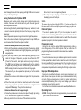
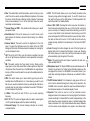
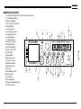
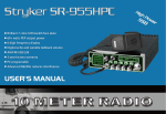
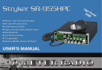
INTRODUCTION
Congratulations on your purchase of a Stryker 10 meter mobile amateur transceiver.Your Stryker is designed to provide
years of enjoyment and trouble-free service. There are many features and functions designed into this transceiver. To ensure
that your investment is enjoyed to its fullest extent, please take a few moments and thoroughly
read this manual.
LIMITED WARRANTY
Stryker Amateur Radio warrants this product to be free of defects for a period of three (3) year from the original date of
purchase. You must activate your warranty by completing the included form or online at www.strykerradios.com/register.
aspx This warranty is non-transferable. This limited warranty is subject to repair or replacement of defective components only.
This warranty is void if the radio has been tampered with or misused. If your Stryker Radios needs repair any time during the (3)
year warranty period please visit our website: www.StrykerRadios.com to obtain an RA number or call 910-221-1086 between
the hours of 10 a.m. – 5 p.m. Eastern standard time. If you do need service after your warranty has expired you can still send
your radio to us for repair. Our rates are very reasonable and you can rest assured that your radio will be fixed correctly.
IMPORTANT: RETAIN YOUR SALES RECEIPT
You will need to include a copy of your original sales receipt along with your radio when sending it in for warranty repair.
INSTALLATION
1. Contents
Unpack and inspect your Stryker SR-655HPC for missing or
damaged Components.
Quantity
1
Description
Stryker SR-655HPC Transceiver
1
Microphone
1
DC Power Cord with Inline Fuse
1
Mounting Bracket with Hardware
1
Microphone Hanger with Hardware Set
Location
Plan the location of the transceiver and microphone brackets
before starting the installation. Select a location that is convenient for
operation and does not interfere with the driver or passengers in the
vehicle. In automobiles, the transceiver is usually mounted below the
dash panel, with the microphone bracket beside it.
Mounting
Your mobile radio is supplied with a universal mounting bracket.
When mounting the bracket and radio to your car, make sure it is
mechanically strong. Also provide a good electrical connection to the
chassis of the vehicle. Proceed as follows to mount the transceiver:
Mount the Transceiver
After you have determined the most convenient location in your
vehicle, hold the mobile radio with the mounting bracket in the exact
location desired. If nothing will Interfere with mounting it in the desired
position, remove the thumbscrews and use the mounting bracket as
a template to mark the holes for the mounting screws. Before drilling
the holes, make sure nothing behind the surface will be damaged or
interfere with the installation.
Electrical Connections
The Stryker SR655 is designed to work on any 13.8 volt DC, negative
ground electrical source. The condition of a vehicle’s electrical system
can have a profound affect on the performance of the radio. A low
battery, worn generator/alternator, or poor voltage regulator will seriously
impair the performance of the transceiver. Any of the above conditions
could result in a high level of receiver noise generation or a Substantial
loss of the transmitter’s RF output. Make sure that all these components
on your vehicle’s electrical system are in good condition prior to installing
the transceiver.
111 Before making any electrical connections make sure the volume (VOL)
control is in the“OFF” position.
222 Connect the positive (+) red wire of the DC power cord to a positive
13.8-volt source at the vehicle fuse block. If connecting to the fuse
block, it is recommended that a switched power source be used so
that the power to the Transceiver is disconnected when the vehicle is 1
off. This eliminates the possibility the transceiver draining the vehicle’s
battery.
333 Connect the negative (-) black wire to a metal part of the vehicle’s
frame, or chassis ground. Make sure that this is a good ground
connection.
Antenna Connections
The Stryker SR-655 has a jack in the rear for a standard PL-259
antenna plug. If you are looking for the most range for your transmission,
use a vertically polarized, quarter-wave length antenna. If antenna height
is a problem, you may use a shorter, loaded-type whip antenna although
you can expect some loss of transmission range. Your antenna should
always be adjusted for the lowest possible SWR (1.5 or less.) To adjust
your antenna for best performance, you can take advantage of your
radio’s built in SWR meter. Failure to properly adjust your antenna(s)
will diminish your operational range and could result in damage to your
radio. Damage that results from operating with high SWRs is not covered
under your factory warranty!
Tuning the Antenna for Optimum SWR
2
Once it is cut, it can no longer be lengthened.
333The whip is easily cut by filing a notch all the way around, then
breaking the piece off with pliers.
Because such a wide variety of base and mobile antennas are
available, this section will concern itself only with the usual types of
mobile adjustable antennas.
Antenna length is directly related to signal frequency. Therefore, it must
be tuned to resonate optimally throughout the frequency range of the
transceiver.
Lower frequencies require a longer antenna than higher frequencies.
Due to the various methods of adjusting antennas for proper SWR, we
have chosen what we think is the optimum method:
NOTE:
The proper setting is achieved when the SWR is 1.5 or below and when it has
the same reading for the low and high frequencies in the range you plan to use.
A. Antennas with adjustable screws (setscrews).
111 Start with the antenna extended and tighten the setscrew lightly
enough so that the antenna can be lightly tapped with your finger for
easy adjustment.
222 Set your Stryker radio to your desired operating frequency or the
center of the range of frequencies you plan to use. Press the PTT
(Press-To-Talk) switch, and tap the antenna (making it shorter).
The SWR meter will show a lower reading each time the antenna
is tapped. By continuing to shorten the antenna, you will notice the
SWR reading will reach a low point and then start rising again.
This means that you have passed the optimum point for the middle
frequency.
333 Extend the antenna a short distance and again follow the procedure
above.
444 When the lowest point has been reached, switch to the lowest
frequency you plan to operate on and then to the highest and
compare SWR readings. They should be almost equal.
Using this jack and the optional USB preprogramming cable you
can change many of the default options that your radio has. Our
programming software is available for download via our website.
B. Antennas that must be cut to proper length.
111 Follow the procedure as in A above, but adjust the length by cutting
in 1∕8" increments until a good match is obtained.
222 Be very careful not to cut too much off the antenna at one time.
External Speaker
The external speaker jack (EXT) on the rear panel is used for
remote receiver monitoring. The external speaker should have 8 ohms
impedance and be able to handle at least four watts. When the external
speaker is plugged in, the internal speaker is disabled.
Programming Jack
Public Address
To use the transceiver as a public address system, connect an external
8 ohm speaker that is able to handle at least four watts to the PA jack on
the rear panel. Direct the speaker away from the microphone to prevent
acoustic feedback. Physical separation or isolation of the microphone
and speaker is important when operating the PA at high output levels.
Improper Radio Adjustments
Service by unqualified technicians could result in damage to your
radio. Never allow anyone to disable your radio’s modulation limiting
circuitry. We have designed your radio for optimal performance
and durability. Disabling this circuitry could damage your radio and
potentially void your factory warranty!
For further service information please visit www.StrykerRadios.com.
Operating Guide
111FUNC: Pressing this button in for approximately three seconds allows
you to access the function menu.
222 Mon: The variable Mon control (talk back) is used to monitor your own
voice.This can be used to compare different microphones. To increase
the volume of the talk back rotate the control clockwise. To decrease
rotate counterclockwise. To turn off the talk back rotate the control
completely counterclockwise.
333 Transmit Power or PWR - This variable control allows you to adjust
your power output.
444 Band Selector: This switch allows you to switch bands, each
band contains 40 channels, with each channel being on a different
frequency.
555 Dimmer Switch: This switch controls the brightness for the front
panel. To adjust the brightness move this switch to the left “DIM”
setting and then rotate the channel selector clockwise for more light or
counter-clockwise for less.
666 HIC: This is the Hi-Cit Filter, once this function is enabled, the radio
will cut out high frequency interference. Use is dependent on reception
conditions.
777 RB: This switch controls the "roger beep" circuitry. Simply put the
roger beep is a tone that sounds when a radio operator un-keys their
microphone. When the switch is on the RB position the roger beep is
turned on. When moved the switch is moved to the middle position it is
switched off.
888 PRG: This switch allows you to select which roger beep is will be
activated when the RB switch is on. It also allows you select if you’d
like the auto squelch activated and lets you add specific channels to
scanned when the scan feature is activated. See section “PRG Menu”
for more details on this function.
999 +10Khz-: This switch will add 10 Khz to your current operating
frequency.
1111RX / TX: The TX symbol will appear when the radio is receiving and
the TX symbol will appear when the radio is transmitting.
1111Channel Display: The channel display indicates the currently
selected channel.
1111VFO: The VFO switch allows you to move through the radios entire
frequency range without changing bands. To use VFO mode move
this switch all the way to the right position. For Band operation this
switch should be in the middle position.
1111Scan / CH9 / CH19: Pressing this button once when the radio is in
band mode will automatically take you to CH9 of which ever band
you are currently on. Pressing it a second time will bring you to CH19
on your current band. To scan channels in band mode you must first
press and release the FUNC button and then press the Scan button,
the radio will then start to scan. In VFO mode this button will only
enable scanning, therefore it’s notnecessary to first press the FUNC
button.
1111Color: Pressing this button changes the color of the front panel and
display. Each time it’s pressed it will change to a new color. Pressing
this button allows you to select the color loop mode where the radio
will automatically cycle through all of the colors.
1111Mode: This switch controls what mode of operation the radio is in,
3
option are AM, FM & PA.
1111Microphone Input: The Stryker SR655 accepts microphones with a
female 4 pin connector. For further wiring information please see the
next page of this manual. Our SR-65BC is an excellent choice if you
need noise canceling microphone. Please see our website for further
details.
1111On/Off Volume Control: Turn clockwise to apply power to the unit
and to set the desired listening level. During normal operation, the
VOLUME control is used to adjust the output level obtained either at
the transceiver speaker or the external speaker, if used.
1111Squelch: This control is used to cut off or eliminate receiver
background noise in the absence of an incoming signal. For maximum
receiver sensitivity it is desired that the control be adjusted only to the
point where the receiver background noise or ambient backgrounds
noise is eliminated. Turn fully counterclockwise then slowly clockwise
until the receiver noise disappears. Any signal to be received must
now be slightly stronger than the average received noise.
1111Microphone Gain: Adjusts the microphone gain in the transmit and
PA modes. This controls the gain to the extent that full talk power is
available several inches away from the microphone.
2222RF Gain: This control is used to reduce the gain of the RF (receive)
amplifier under strong signal conditions. For maximum receiver
sensitivity this control should be turn all the way to the right
(clockwise).
2222Noise Blanker / ANL Switch: When this switch is in the NB position
the noise Blanker circuits are activated. The Noise Blanker is very
effective in eliminating repetitive pulse type noise usually associated
with ignition systems. The ANL position activates both the Noise
Blanker and Automatic Noise Limiter (ANL) Circuitry.
2222Echo Volume: Varies the volume or number of echo repetitions. To
increase the echo volume, rotate the control clockwise.
2222Echo Delay: The Echo switch turn the echo on. A big advantage to
this is you can turn it off and then back on with the switch without the
4
need to adjust your volume & delay potentiometer. To turn the echo
off simply move the switch to the middle position.
2222Vox: This control is used for turning the VOX function on as well as
adjusting the sensitivity of it. If you are not using a vox headset or
microphone you should leave this control turned all the way counter
clockwise.
2222COA: This control operates slightly differently than a typical clarifier.
At the 12 o'clock position it will be at +0K, tuning one click to the right
will add +5K and once more to the right will add +10K. The opposite
would be true when turned to the left from the 12 o'clock position. The
first click to the left would be -5K and the second click would be -10K.
You will find that this is much more useful than a clarifier typically is
on an AM/FM radio.
2222Channel Selector: This control is used to select the desired transmit
and receive channel.
OPERATION GUIDE
For detailed descriptions of all functions please see page.
111 Function Menu Button
222 Monitor (Talkback)
333 RF Power Output Control
444 Band Selector
555 Dimmer Switch
2
666 Hi-Cut Receive Filter
777 Roger Beep Switch
1
888 Program Switch
999 +10 KHz Switch
1111Receive / Transmit
STRYKER
1111Channel Display
1111VFO Mode Switch
1111Scan / CH9 / CH19
FUNC
1111Color Button
COLOR
1111Mode Switch
SCAN
1111Microphone Jack
CH19
1111Receiver Volume
1111Receiver Squelch
SR-655HP
1111Microphone Gain
2222RF Gain
2222Noise Blanker / ANL
15
14
13
2222Echo Volume
2222Echo Delay
2222Vox Adjustment
16
2222Coarse Clarifier Adjustment
2222Channel Selector
MON
11
4
3
6
5
PWR
C
B
E
AM FM PA
VOL
DIM
SQ
8
HIC
MIC
ANL
RF
NB
RB
VOL
PRG
DEL
TONE
GAIN
19
+10KHz
VOX
24
20
21
ECH
22
23
5
COA
FREQUENCY
CLAR
18
17
12
10
10 Meter Amateur Mobile Transceiver
D
A
7
9
25
26
ALTERNATE MICROPHONES AND INSTALLATION
For best results, the user should select a low-impedance dynamic
type microphone or a transistorized microphone. Transistorized
type microphones have low output impedance characteristics. The
microphones must be provided with a four-lead cable. The audio
conductor and its shielded lead comprise two of the leads. The third
lead is for transmit control and fourth is for receiving control.
The microphone should provide the functions shown in the
schematic below.
Before beginning the actual wiring, read carefully the circuit and wiring
information provided with the microphone you select. Use the minimum
heat required in soldering the connections. Keep the exposed wire
lengths to a minimum to avoid shorting when the microphone plug is
reassembled.
4 WIRE MIC CABLE
6
Pin Number
1
2
3
4
Mic Cable Lead
Audio Shield
Audio Lead
Transmit Control
Receive Control
If the microphone to be used is provided with pre-cut leads, they must
be revised as follows.
111 Cut leads so that they extend 7/16" beyond the plastic insulating jacket
of the microphone cable.
222 All leads should be cut to the same length. Strip the ends of each wire
1/8" and tin the exposed wire.
To wire the microphone cable to the plug provided, proceed as follows:
111 Remove the retaining screw.
222 Unscrew the housing from the pin receptacle body.
333 Loosen the two cable clamp retainer screws.
444 Feed the microphone cable through the housing, knurled ring and
washer as shown Figure 2.
Function Menu Navigation
The function menu allows you to customize many features as well as
controls that your Stryker SR-655HP has to offer. To access the function
menu press and hold the FUNC Button for approximately two seconds
until the LCD meter displays FIN, then release the function button. Then
press the FUNC button again to choose a difference function menu item.
Turning the channel selector knob will change the value of the function.
If you’d ike to reset all of these options to the default settings, please
do the following. With the radio turned off, press and hold the FUNC,
COLOR & SCAN buttons. While still pressing and holding them, power
the radio on. The radio will display “REST ALL”, now release the buttons
and wait for the radio to display “REST END”. Then turn the radio off and
then back on, it’s now been restored to the factory software settings .
GRO: This allows you to select what bands are available using the
band selector knob. The first option is A-E and the second is F-L.
ASQ: (Automatic Squelch Control) The only options for this function
are on or off.
CHS: Channel step can be changed in this setting, option are; 1 Khz,
10 Khz, 100 Khz & 1 Mhz. This setting is used when the radio is in VFO
mode. If you are in VFO mode, press and hold the FUNC button and
rotate the frequency selector, this allows you to change the step size
without going into the function menu.
Beep: The default setting for this is on, but many user may wish to
turn this off as well. This function basically emits an audible beep when
a feature is turned on or off, for example moving the NB switch to NB+
position.
TOT: This menu is used to set transmitting limit time. When pressing
PTT key at a single time longer than the due time setup in advance, the
radio would stop transmitting automatically and the speaker will emit a
voice prompt until the PTT key is released. Then, the radio can transmit
again.
Options: 30-600s Step: 30s Default: 180s
SCM: This menu is used to set the Scan mode. Options are as
follows: SQ: When SQ is selected, scan would stop when a valid signal
is detected. The radio would resume scanning after signal disappears
for 5s. TI: When TI is selected, scan would stop when a valid signal is
detected. The radio would resume scanning 5 seconds later, whether
signal disappears or not. Default: SQ
SCT: Scan resume time. When the scanned signal disappears, how
many seconds before it will start to scan again. Options: 5S 10S 15S.
TSR: Choose whether to enable the Transmitting SWR Protection
function or not.
ON: When ON is selected, the radio will detect the SWR of your
antenna. Once the SWR is beyond the SWR limit set in advance, the
radio would stop transmitting automatically and the speaker will emit a
voice prompt. Then, “HI S” icon will display on the LCD to remind you
that the antenna SWR is too high.
OFF: When OFF is selected, the SWR Protection function is disabled. 7
NOTE: To protect the radio from long transmission under high SWR, the
radio would automatically start SWR Protection once the SWR Value is
higher than 20:1.
TDC: Choose whether to enable Voltage Protection function or not.
ON: When ON is selected, the radio will detect the supplied voltage.
Once the voltage surpasses the limit that was set in advance, the radio
would display “DC LO” or “DC HI” to remind you that the voltage is not
in normal state. Meanwhile, the radio will prohibit transmitting and emit a
beep sound.
OFF: When OFF is selected, the Power Supplying Voltage is disabled.
Default: ON
LCD: This option lets you choose if you’d like to display the following
on the LCD meter. The first option is to display the model name of the
radio, the second option will display the DC voltage present at the power
jack and the third option will display the model name during receive and
the voltage during transmit.
LOPT: The last option in the function menu is the the back light scan
intervals, you can choose from 0.5 - 10 seconds.
PRG Menu Navigation
With the RB * PRG switch in the right position the LCD meter will
display “1. Scan” rotating the channel selector will give you a second
option “2. RB”.
8
Scan - With the scan option displayed on the meter, press the FUNC
button once and “Scan Add” will be displayed on the meter, pressing the
FUNC button again will add your current channel to the list of channels
to be scanned when the scan feature is activated. To delete a channel
from the scan list do the following. When “Scan Add” is display on the
meter, rotate the channel selector once to the right and “Scan Del” will be
displayed. Press the FUNC button and this channel will now be deleted
from the scan list.
RB - This function lets you choose from a total of 6 roger beep. When
the “2.RB” is displayed on meter, press the FUNC button once. You
should now see “RB 1” rotating the channel selector to the right allows
you to cycle through the roger beeps (RB 1-6). To select a roger beep
press the FUNC button once. Now selected roger been will be activated
when the “RB - PRG” button in in the left position.
A1.0-12/11