1
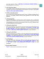
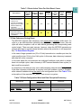
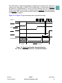
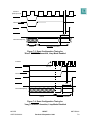
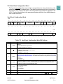
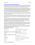
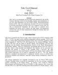
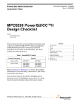
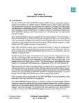
SECTION 7
RESET
This section describes the MPC555 reset sources, operation, control, and status.
7.1 Reset Operation
The MPC555 has several inputs to the reset logic which include the following:
• Power on reset
• External hard reset pin (HRESET)
• External soft reset pin (SRESET)
• Loss of lock
• On-chip clock switch
• Software watchdog reset
• Checkstop reset
• Debug port hard reset
• Debug port soft reset
• JTAG reset
All of these reset sources are fed into the reset controller. The control logic determines
the cause of the reset, synchronizes it if necessary, and resets the appropriate logic
modules, depending on the source of the reset. The memory controller, system protection logic, interrupt controller, and parallel I/O pins are initialized only on hard reset.
External soft reset initializes internal logic while maintaining system configuration.
The reset status register (RSR) reflects the most recent source to cause a reset.
7.1.1 Power On Reset
The power-on reset pin, PORESET, is an active low input. In a system with powerdown low-power mode, this pin should be activated only as a result of a voltage failure
in the KAPWR pin. After detecting the assertion of PORESET, the MPC555 enters the
power-on reset state. During this state the MODCK[1:3] signals determine the oscillator frequency, PLL multiplication factor, and the PITRCLK and TMBCLK clock
sources. In addition, the MPC555 asserts the SRESET and HRESET pins.
The PORESET pin should be asserted for a minimum time of 100,000 cycles of clock
oscillator after a valid level has been reached on the KAPWR supply. After detecting
the assertion of PORESET, the MPC555 remains in the power-on reset state until the
last of the following two events occurs:
• The Internal PLL enters the lock state and the system clock is active.
• The PORESET pin is negated.
If the MPC555 is in single-chip mode and limp mode is enabled, the internal PLL is not
required to be locked before the chip exits power-on reset.
MPC555
USER’S MANUAL
RESET
Revised 15 September 1999
MOTOROLA
7-1
After exiting the power-on reset state, the MCU continues to drive the HRESET and
SRESET pins for 512 system clock cycles. When the timer expires (after 512 cycles),
the configuration is sampled from data bus pins, if required (see 7.5.1 Hard Reset
Configuration) and the MCU stops driving the HRESET and SRESET pins. In addition, the internal MODCK[1:3] values are sampled.
The PORESET pin has a glitch detector to ensure that low spikes of less than 20 ns
are rejected. The internal PORESET signal asserts only if the PORESET pin asserts
for more than 100 ns.
7.1.2 Hard Reset
HRESET (hard reset) is an active low, bi-directional I/O pin. The MPC555 can detect
an external assertion of HRESET only if it occurs while the MCU is not asserting reset.
When the MPC555 detects assertion of the external HRESET pin or a cause to assert
the internal HRESET line, is detected the chip starts to drive the HRESET and SRESET for 512 cycles. When the timer expires (after 512 cycles) the configuration is
sampled from data pins (refer to 7.5.1 Hard Reset Configuration) and the chip stops
driving the HRESET and SRESET pins. An external pull-up resistor should drive the
HRESET and SRESET pins high. After detecting the negation of HRESET or SRESET, the MCU waits 16 clock cycles before testing the presence of an external hard
or soft reset.
The HRESET pin has a glitch detector to ensure that low spikes of less than 20 ns are
rejected. The internal HRESET will be asserted only if HRESET is asserted for more
than 100 ns.
The HRESET is an open collector type pin.
7.1.3 Soft Reset
SRESET (soft reset) is an active low, bi-directional I/O pin. The MPC555 can only
detect an external assertion of SRESET if it occurs while the MPC555 is not asserting
reset.
When the MPC555 detects the assertion of external SRESET or a cause to assert the
internal SRESET line, the chip starts to drive the SRESET for 512 cycles. When the
timer expires (after 512 cycles) the debug port configuration is sampled from the DSDI
and DSCK pins and the chip stops driving the SRESET pin. An external pull-up resistor
should drive the SRESET pin high. After the MPC555 detects the negation of SRESET, it waits 16 clock cycles before testing the presence of an external soft reset.
7.1.4 Loss of Lock
If the PLL detects a loss of lock, erroneous external bus operation will occur if synchronous external devices use the MPC555 input clock. Erroneous operation could
also occur if devices with a PLL use the MPC555 CLKOUT signal. This source of reset
can be optionally asserted if the LOLRE bit in the PLL, low-power, and reset control
register (PLPRCR) is set. The enabled PLL loss of lock event generates an internal
MPC555
USER’S MANUAL
RESET
Revised 15 September 1999
MOTOROLA
7-2
hard reset sequence. Refer to SECTION 8 CLOCKS AND POWER CONTROL for
more information on loss of lock.
7.1.5 On-Chip Clock Switch
If the system clocked is switched to the backup clock or switched from backup clock
to another clock source an internal hard reset sequence is generated. Refer to SECTION 8 CLOCKS AND POWER CONTROL.
7.1.6 Software Watchdog Reset
When the MPC555 software watchdog counts to zero, a software watchdog reset is
asserted. The enabled software watchdog event generates an internal hard reset
sequence.
7.1.7 Checkstop Reset
When the RCPU enters a checkstop state, and the checkstop reset is enabled (the
CSR bit in the PLPRCR is set), a checkstop reset is asserted. The enabled checkstop
event generates an internal hard reset sequence. Refer to the RCPU Reference Manual (RCPURM/AD) for more information.
7.1.8 Debug Port Hard Reset
When the development port receives a hard reset request from the development tool,
an internal hard reset sequence is generated, see SECTION 8 CLOCKS AND
POWER CONTROL. In this case the development tool must reconfigure the debug
port. Refer to SECTION 21 DEVELOPMENT SUPPORT for more information.
7.1.9 Debug Port Soft Reset
When the development port receives a soft reset request from the development tool,
an internal soft reset sequence is generated, see SECTION 8 CLOCKS AND POWER
CONTROL. In this case the development tool must reconfigure the debug port. Refer
to SECTION 21 DEVELOPMENT SUPPORT for more information.
7.1.10 JTAG Reset
When the JTAG logic asserts the JTAG soft reset signal, an internal soft reset
sequence is generated, see SECTION 8 CLOCKS AND POWER CONTROL. Refer
to SECTION 22 IEEE 1149.1-COMPLIANT INTERFACE (JTAG) for more
information.
7.2 Reset Actions Summary
Table 7-1 summarizes the action taken for each reset.
MPC555
USER’S MANUAL
RESET
Revised 15 September 1999
MOTOROLA
7-3
Table 7-1 Reset Action Taken For Each Reset Cause
Reset Source
Power On Reset
Hard Reset Sources
External Hard Reset
Loss of Lock
On-Chip Clock Switch
Illegal Low-Power Mode
Software Watchdog
Checkstop
Debug Port Hard Reset
Soft Reset Sources
External Soft Reset
Debug Port Soft Reset
JTAG Reset
Reset
System
Logic and
ConfiguraPLL States
tion Reset
Reset
Yes
Yes
Clock
Module
Reset
Yes
Debug
HRESET
Port
Pin Driven Configuration
Yes
Yes
Other
Internal
Logic
Reset
Yes
SRESET
Pin Driven
Yes
No
Yes
Yes
Yes
Yes
Yes
Yes
No
No
No
No
Yes
Yes
Yes
7.3 Data Coherency During Reset
The MPC555 supports data coherency and avoids data corruption while reset. If a
cycle is to be executed when detecting any SRESET or HRESET source, then the
cycle will either complete or will not start before generating the corresponding reset
control signal. There are reset sources, however, when the MPC555 generates an
internal reset due to special internal situation where this protection is not supported.
See 7.4 Reset Status Register.
In the case of large operand size (32 or 16 bits) transaction to a smaller port size, the
cycle is split into two 16-bit or four 8-bit cycles. In this case, data coherency is assured
and data will not be corrupted.
In the case where the core executes an unaligned load/store cycle which is broken
down into multiple cycles, data coherency is NOT assured between these cycles (i.e.
data could be corrupted).
A contention on the data pins may occur while asserting external reset (EXT_RESET)
if the data coherency mechanism is required, and thus enables a cycle to complete,
while external hardware drives the data for the configuration word. See Table 7-2 for
a description of the required EXT_RESET line source in a system.
Table 7-2 Reset Configuration Word and Data Corruption/Coherency
Reset Driven
Reset to Use for Data Coherency
(EXT_RESET)
HRESET
SRESET
SRESET
HRESET
HRESET & SRESET
HRESET || SRESET
MPC555
USER’S MANUAL
RESET
Revised 15 September 1999
Comments
Provided only one of them is driven
into the MPC555 at a time
MOTOROLA
7-4
7.4 Reset Status Register
All of the reset sources are fed into the reset controller. The 16-bit reset status register
(RSR) reflects the most recent source, or sources, of reset. (Simultaneous reset
requests can cause more than one bit to be set at the same time.) This register contains one bit for each reset source. A bit set to logic one indicates the type of reset that
occurred.
Once set, individual bits in the RSR remain set until software clears them. Can be
cleared by writing a one to the bit. A write of zero has no effect on the bit. The register
can be read at all times. The reset status register receives its default reset values during power-on reset. The RSR is powered by the KAPWR pin.
RSR — Reset Status Register
0x2F C288
MSB
0
1
2
3
4
EHRS
ESRS
LLRS
SWRS
CSRS
0
0
0
0
5
6
DBHRS DBSRS
7
8
9
JTRS
OCCS
ILBC
0
0
0
10
11
12
13
GPOR GHRST GSRST
14
15
RESERVED
RESET:
0
0
0
1
1
1
0
0
0
Table 7-3 Reset Status Register Bit Settings
Bit(s)
Name
Description
0
EHRS1
External hard reset status
0 = No external hard reset has occurred
1 = An external hard reset has occurred
1
ESRS1
External soft reset status
0 = No external soft reset has occurred
1 = An external soft reset has occurred
2
LLRS
Loss of lock reset status
0 = No enabled loss-of-lock reset has occurred
1 = An enabled loss-of-lock reset has occurred
3
SWRS
Software watchdog reset status
0 = No software watchdog reset has occurred
1 = A software watchdog reset has occurred
4
CSRS
Checkstop reset status
0 = No enabled checkstop reset has occurred
1 = An enabled checkstop reset has occurred
5
DBHRS
Debug port hard reset status
0 = No debug port hard reset request has occurred
1 = A debug port hard reset request has occurred
6
DBSRS
Debug port soft reset status
0 = No debug port soft reset request has occurred
1 = A debug port soft reset request has occurred
7
JTRS
JTAG reset status
0 = No JTAG reset has occurred
1 = A JTAG reset has occurred
MPC555
USER’S MANUAL
RESET
Revised 15 September 1999
MOTOROLA
7-5
Table 7-3 Reset Status Register Bit Settings (Continued)
Bit(s)
8
9
10
11
12
13:15
Name
Description
OCCS
On-chip clock switch
0 = No on-chip clock switch reset has occurred
1 = An on-chip clock switch reset has occurred
ILBC
Illegal bit change. This bit is set when the MPC555 changes any of the following bits when they
are locked:
LPM[0:1], locked by the LPML bit
MF[0:11], locked by the MFPDL bit
DIVF[0:4], locked by the MFPDL bit
GPOR
Glitch detected on PORESET pin. This bit is set when the PORESET pin is asserted for more
than TBD ns
0 = No glitch was detected on the PORESET pin
1 = A glitch was detected on the PORESET pin
GHRST
Glitch detected on HRESET pin. This bit is set when the HRESET pin is asserted for more than
TBD ns
0 = No glitch was detected on the HRESET pin
1 = A glitch was detected on the HRESET pin
GSRST
Glitch detected on SRESET pin. If the SRESET pin is asserted for more than TBD ns the
GHRST bit will be set. If an internal or external SRESET is generated the SRESET pin is
asserted and the GSRST bit will be set. The GSRST bit remains set until software clears it. The
GSRST bit can be negated by writing a one to GSRST. A write of zero has no effect on this bit.
0 = No glitch was detected on SRESET pin
1 = A glitch was detected on SRESET pin.
—
Reserved
NOTES:
1. In the USIU RSR, if both EHRS and ESRS are set, the reset source is internal. The EHRS and ESRS bits in RSR
register are set for any internal reset source in addition to external HRESET and external SRESET events. If both
internal and external indicator bits are set, then the reset source is internal.
7.5 Reset Configuration
7.5.1 Hard Reset Configuration
When a hard reset event occurs, the MPC555 reconfigures its hardware system as
well as the development port configuration The logical value of the bits that determine
its initial mode of operation, are sampled from the following:
• The external data bus pins DATA[0:31]
• An internal default constant (0x0000 0000)
• An internal NVM register value (CMFCFIG)
If at the sampling time RSTCONF is asserted, then the configuration is sampled from
the data bus. If RSTCONF is negated and a valid NVM value exists (CMFCFIG bit
HC=0), then the configuration is sampled from the NVM register in the CMF module.
If RSTCONF is negated and no valid NVM value exists (CMFCFIG bit HC=1), then the
configuration word is sampled from the internal default. HC will be “1” if the internal
flash is erased. Table 7-4 summarizes the reset configuration options.
MPC555
USER’S MANUAL
RESET
Revised 15 September 1999
MOTOROLA
7-6
Table 7-4 Reset Configuration Options
RSTCONF
Has Configuration (HC)
Internal Configuration Word
0
x
DATA[0:31] pins
1
0
NVM flash EEPROM register (CMFCFIG)
1
1
Internal data word default (0x0000 0000)
If the PRDS control bit in the PDMCR register is set and HRESET and RSTCONF are
asserted, the MPC555 pulls the data bus low with a weak resistor. The user can overwrite this default by driving the appropriate bit high. See Figure 7-1 for the basic reset
configuration scheme.
Has Configuration HC
Config.
Word
32
MUX
CMF
32
32
OE
Dx (Data line)
INT_RESET
Data
Coherency
EXT_RESET
(See Table 7.2)
HRESET/SRESET
RSTCONF
MPC555
Figure 7-1 Reset Configuration Basic Scheme
During the assertion of the PORESET input signal, the chip assumes the default reset
configuration. This assumed configuration changes if the input signal RSTCONF is
asserted when the PORESET is negated or the CLKOUT starts to oscillate. To ensure
MPC555
USER’S MANUAL
RESET
Revised 15 September 1999
MOTOROLA
7-7
that stable data is sampled, the hardware configuration is sampled every eight clock
cycles on the rising edge of CLKOUT with a double buffer. The setup time required for
the data bus is approximately 15 cycles, and the maximum rise time of HRESET
should be less than 6 clock cycles. In systems where an external reset configuration
word and the TEXP output function are both required, RSTCONF should be asserted
until SRESET is negated.
Figure 7-2 to Figure 7-5 provide sample reset configuration timings.
CLKOUT
PORESET
Internal PORESET
HRESET
RSTCONF
Tsup
Internal DATA[0:31]
Default
RSTCONF Controlled
Figure 7-2 Reset Configuration Sampling Scheme
For “Short” PORESET Assertion, Limp Mode Disabled
MPC555
USER’S MANUAL
RESET
Revised 15 September 1999
MOTOROLA
7-8
CLKOUT
(Backup Clock)
PORESET
Internal PORESET
HRESET
RSTCONF
Tsup
Internal DATA(0:31)
Default
RSTCONF Controlled
Figure 7-3 Reset Configuration Timing for
“Short” PORESET Assertion, Limp Mode Enabled
CLKOUT
PLL lock
PORESET
Internal PORESET
HRESET
RSTCONF
Tsup
Internal DATA[0:31]
Default
RSTCONF Controlled
Figure 7-4 Reset Configuration Timing for
“Long” PORESET Assertion, Limp Mode Disabled
MPC555
USER’S MANUAL
RESET
Revised 15 September 1999
MOTOROLA
7-9
Figure 7-5 Reset Configuration Sampling Timing Requirements
MPC555
USER’S MANUAL
Revised 15 September 1999
RESET
MOTOROLA
7-10
3
4
5
6
7
8
10
11
12
13
14
15
Maximum time of reset recognition
(maximum rise time - up to 6 clocks)
9
Sample Data Configuration
Tsup = Minimum Setup time of reset recognition = 15 clocks
RESET CONFIGURATION WORD
2
Sample Data Configuration
Internal
reset
Data
RSTCONF
HRESET
CLKOUT
1
16
7.5.2 Hard Reset Configuration Word
The hard reset configuration word, which is sampled from the internal data bus on the
negation of HRESET, is shown below. The reset configuration word is not a register in
the memory map. Most of the bits in the configuration are located in registers in the
USIU. The user should refer to the appropriate register definition for a detailed description of each control bit.
Hard Reset Configuration Word
MSB
0
1
2
3
EARB
IP
BDRV
BDIS
0
0
4
5
6
BPS
7
8
9
Reserved
10
DBGC
11
12
13
DBPC ATWC
14
15
Reserved
EBDF
DEFAULT:
0
0
0
0
0
0
0
0
0
0
0
0
0
0
LSB
16
17
PRPM
18
SC
19
20
ETRE
FLEN
0
0
21
22
Reserved
23
24
CLES
25
26
27
28
Reserved
29
30
ISB
31
DME
DEFAULT:
0
0
0
0
0
0
0
0
0
0
0
0
0
0
Table 7-5 Hard Reset Configuration Word Bit Settings
Bit(s)
0
Name
EARB
Description
External arbitration. Refer to 6.13.1.1 SIU Module Configuration Register for a detailed bit
definition.
0 = Internal arbitration is performed
1 = External arbitration is assumed
IP
Initial interrupt prefix. This bit defines the initial value of the MSR[IP] bit immediately after reset.
MSR[IP] defines the interrupt table location.
0 = MSR[IP] = 0 after reset
1 = MSR[IP] = 1 after reset
2
BDRV
Bus pins drive strength. This bit determines the driving capability of the bus pins (address, data,
and control) and the CLKOUT pin. For details, refer to description of the COM bits in 8.12.1 System Clock Control Register (SCCR). The default value is full drive strength for the bus pins and
CLKOUT.
0 = Full drive
1 = Reduced drive
3
BDIS
External boot disable. If a write to the OR0 register occurs after reset, this bit definition is ignored.
0 = Memory controller bank 0 is active and matches all addresses immediately after reset
1 = Memory controller is not activated after reset.
4:5
BPS
Boot port size. If a write to the OR0 register occurs after reset, this field definition is ignored.
00 = 32-bit port (default)
01 = 8-bit port
10 = 16-bit port
11 = Reserved
6:8
—
9:10
DBGC
1
MPC555
USER’S MANUAL
Reserved
Debug pins configuration. See 6.13.1.1 SIU Module Configuration Register for this field definition. The default value is for these pins to function as VFLS[0:1], BI, BR, BG, and BB.
RESET
Revised 15 September 1999
MOTOROLA
7-11
Table 7-5 Hard Reset Configuration Word Bit Settings (Continued)
Bit(s)
Name
Description
11
DGPC
Debug port pins configuration. See 6.13.1.1 SIU Module Configuration Register for this field
definition. The default value is for these pins to function as development support pins.
12
ATWC
Address type write-enable configuration. Refer to 6.13.1.1 SIU Module Configuration Register
for this field definition. The default value is for these pins to function as write-enable pins.
13:14
EBDF
External bus division factor. This field defines the initial value of the external bus frequency. Refer
to 8.12.1 System Clock Control Register (SCCR) for details. The default value is that CLKOUT
frequency is equal to that of the internal clock (divide by one).
15
—
16
PRPM
Reserved
Peripheral mode enable. This bit determines whether the chip is in peripheral mode. Refer to
6.13.1.3 External Master Control Register (EMCR) for details. The default value is that peripheral mode is not enabled.
Single chip select. Refer to 6.13.1.1 SIU Module Configuration Register for details.
00 = Extended chip, 32 bits data
01 = Extended chip, 16 bits data
10 = Single chip and show cycles (address)
11 = Single chip
17:18
SC
19
ETRE
Exception table relocation enable. This field defines whether the exception table relocation feature in the BBC is enabled or disabled. The default state is disabled. Refer to SECTION 4 BURST
BUFFER for details.
20
FLEN
Flash enable. Refer to 6.13.1.2 Internal Memory Map Register for details.
0 = Flash disabled — boot is from external memory
1 = Flash enabled
21:22
—
23
CLES
24:27
—
28:30
ISB
Initial internal space base select. This field defines the initial value of the ISB field in the IMMR
register. Refer to 6.13.1.2 Internal Memory Map Register for details. The default state is that
the internal memory map is mapped to start at address 0x0000 0000.
DME
Dual mapping enable. This bit determines whether dual mapping of the flash EEPROM module
is enabled. Refer to 10.8.5 Dual Mapping Base Register (DMBR) for details.The default value
is for dual mapping to be disabled.
0 = Dual mapping disabled
1 = Dual mapping enabled
31
Reserved
Core little-endian swap. Refer to 6.13.1.2 Internal Memory Map Register for details.
0 = Little-endian swap logic not activated
1 = Little-endian swap logic in the EBI is activated for core (RCPU) accesses after reset.
Reserved
7.5.3 Soft Reset Configuration
When a soft reset event occurs, the MPC555 reconfigures the development port. Refer
to SECTION 21 DEVELOPMENT SUPPORT for details.
MPC555
USER’S MANUAL
RESET
Revised 15 September 1999
MOTOROLA
7-12