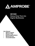
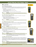
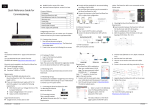
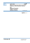
1
99 Washington Street Melrose, MA 02176 Phone 781-665-1400 Toll Free 1-800-517-8431 Visit us at www.TestEquipmentDepot.com HD110C User Manual English Heavy-Duty Digital Multimeter HD110C Features HD110C 6 5 7 4 2 0 0 2 0 2 8 HD110C 3 2 mA 20 mA 200 OFF 1500 A 1000 V 200 V 20 V 200 mA 2 V 2A 200 mV 9 20 M 2 200 2 k 20 k A 1 Number 200 k V COM 2A MAX FUSED 2 M MAX 1500V 1000V CAT IV 1000 V Description 1 COM Input - common or low input for all measurements 2 Amp Input 3 Function/Range Selector Switch 4 Low Battery Indicator 5 Hold Indicator 6 3 ½ Digit LCD with unit indicators 7 AC/DC Button 8 Hold Button 9 High input - voltage and resistance HD110C Heavy-Duty Digital Multimeter Contents Symbols......................................................................................................................................................... 2 Introduction.................................................................................................................................................. 2 Warnings and Precautions........................................................................................................................... 2 Instrument Familiarization.......................................................................................................................... 3 Overload Indication..................................................................................................................................... 3 Measuring Procedures................................................................................................................................. 3 DC & AC Voltage Measurement (See Figure 1).......................................................................................... 4 DC and AC Current Measurement (See Figure 2)....................................................................................... 4 Resistance Measurement (See Figure 3)..................................................................................................... 4 Diode and Continuity Test (See Figure 4)................................................................................................... 4 AC/DC Button............................................................................................................................................... 5 Hold Button.................................................................................................................................................. 5 Auto-Power Down....................................................................................................................................... 5 Incorrect Input Warning.............................................................................................................................. 5 Safety Test Leads.......................................................................................................................................... 5 Optional Accessories.................................................................................................................................... 5 Specifications................................................................................................................................................ 6 Maintenance & Repair................................................................................................................................. 8 Battery / Fuse Replacement (See Figure 5)................................................................................................. 8 Repair............................................................................................................................................................ 9 Symbols B � � � � � � Battery Double insulated Direct Current Alternating Current Fuse Conforms to relevant Australian standards. � � � � � �® Refer to the manual Dangerous Voltage Earth Ground Audible tone Complies with EU directives Canadian Standards Association. [Note: Canadian and US.] Do not dispose of this product as unsorted municipal waste. Contact Amprobe or a qualified recycler for disposal. Introduction The HD110C Heavy-Duty Digital Multimeter is a 3-1/2 digit, manual ranging, ac-coupled average measuring rms reading display instrument that measures: voltage, current, resistance, continuity, and diode junctions. Menu selection allows Data Hold and ac or dc voltage and current selection. Warnings and Precautions This instrument is EN61010-1 certified for Cat IV, 1000 V ac/1500 V dc and lower installations. Based on EN61010-1 transient requirements, this product should only be used in installations where transients do not exceed 12,000 volts (a 1.2 µS/50 µS pulse). • All inputs are protected against continuous overload conditions up to the limits of each function's stated input protection (see specifications). Never exceed these limits or the ratings marked on the instrument itself. • Exercise extreme caution when: measuring voltag e >20 V, current >10 mA, ac power line with inductive loads, ac power line during electrical storms. High voltages can be lethal and high voltage transients may occur at any time. • Operator injury or damage to the multimeter may occur during current measurements if the fuse blows in a circuit with open circuit voltage exceeding 1000 V ac/1500 V dc. • Always inspect your DMM, test leads and accessories for signs of damage or abnormality before use. If an abnormal condition exists (broken or damaged test leads, cracked case, display not reading, etc.), do not use. The internal fuse cover is integral to the EN61010-1 Cat IV safety rating and must be in place to avoid potential shock hazards • When testing for voltage or current, make sure these ranges function correctly. Take a reading of a known voltage or current first. • Never ground yourself when taking measurements. Do not touch exposed metal pipes, outlets, fixtures, etc., which might be at ground potential. Keep your body isolated from ground and never touch exposed wiring, connections, test probe tips, or any live circuit conductors. Do not use the Flex-Strap to attach the meter to your body. • Always measure current in series with the load – NEVER connect the multimeter Test Equipment Depot - 800.517.8431 - 99 Washington Street Melrose, MA 02176 FAX 781.665.0780 - TestEquipmentDepot.com ACROSS a voltage source. Check fuse first. • Never replace a fuse with one of a different rating. • Do not operate instrument in an explosive atmosphere (flammable gases, fumes, vapor, dust.) • Do not use this or any piece of test equipment without proper training • CRT SERVICE SAFETY REMINDER: A potential danger exists when measuring voltages in the horizontal output and damper stages of CRT equipment. (High voltage transients greater than 8000 V). Refer to your CRT service manual for proper servicing instructions. Instrument Familiarization Your shipping carton should include the multimeter, a holster with Magne-Grip hanging strap, one test lead set (one black, one red) threaded alligator clips, one 9 V battery (installed), one 2 mm hex wrench (inside holster) and this manual. If any of the items are damaged or missing, immediately return the complete package to the place of purchase for an exchange. Protective Holster The holster/tilt stand protects the meter form accidental falls and provides greater ease of use. Both test lead probes can be attached to the holster for storage. One probe can be attached for measurement, holding the meter with probe in one hand and the second probe in the other hand. Overload Indication Overload Indication: (input exceeds meter’s highest range) and Display Overload (input exceeds selected range) are both signaled by a 1 displayed on the left side of the LCD. In the volts or amperage ranges Display Overload can be corrected by selecting a higher range to display the input reading. If the highest range is selected and the overload indication continues, this is now an Input Overload. Remove the test leads from the circuit immediately as input exceeds the meter’s rated capability. Note: In both instances, the overload indication is normal in the OHMS and Continuity/Diode ranges to indicate an open circuit. Function Error is signaled a by continuous tone when a test lead is placed in either the 2 A jack and the selector switch is not in the correct current range. If the meter is connected to a voltage source with test leads set for current, very high current could result. All current ranges are protected with fast acting fuses. Battery Low: When the battery low indicator is displayed the battery has less than 50 hours operation and the accuracy of the meter can no longer be guaranteed. Measuring Procedures Turn the meter on by turning the function/range switch away from OFF and selecting the parameter you want to measure. If the parameter selected has more than one range position, the display will indicate the range by a changing position of the decimal point. Always select the highest range if the maximum potential reading is not known. Then turn the selector switch down in range to obtain the best resolution reading. 1. When connecting or disconnecting test leads to a circuit, always turn off power to device or circuit being tested and discharge all capacitors. 2. Strictly observe the max input limits. 3. Do not change functions while test leads are connected to circuit. DC & AC Voltage Measurement (See Figure 1) 1. 2. 3. 4. 5. Connect test leads to the meter as shown in Figure 1. Turn function selector switch to V and the desired range. Press the AC/DC menu button to display either ac or dc indicator. Touch Probe tips across voltage source (in parallel with circuit). Voltage value will appear on Digital Display along with the voltage polarity (for dc). DC and AC Current Measurement (See Figure 2) 1. Connect red test lead to the A input for current measurements up to 2 A. Connect black test lead to COM input connector. 2. Set the Function Switch to the desired current range. 3. Press the AC/DC menu button to display either AC or DC indicator. 4. Open circuit in which current is to be measured (voltage between this point and ground must not exceed 1000 V ac/1500 V dc). Securely connect test leads in series with the load. 5. Turn on power to circuit being tested. 6. Read current value on Digital Display. Incorrect Input Warning: A tone will sound when a test lead is connected to the amperage jack, but the selector switch is not set to the correct current range. Ranges 200 µA to 2 A require the test lead to be in the A jack. Resistance Measurement (See Figure 3) 1. 2. 3. 4. 5. Turn off any power to the resistance to be measured and discharge any capacitors. Any voltage present during a resistance measurement will cause inaccurate readings. Connect test leads to the meter as shown in Figure 3. Set Function/Range Switch to the desired resistance range. Connect test leads to circuit being measured. Read resistance value on digital display. Open circuits will be displayed as “1”. Diode and Continuity Test (See Figure 4) The diode test measures the voltage drop across a diode junction. 1. Connect the test leads as shown in Figure 4. 2. Set the Function/range switch to � �. 3. Apply probe tip of red lead to the anode and the black lead to the cathode of the diode. 4. The meter’s display indicates the forward voltage drop (approx. 0.6 V for silicon diode or 0.4 V for germanium diode). An open diode is indicated by “1”. 5. Reverse test lead connections to the diode to perform a reverse bias test. “1” indicates a good diode. Notes: “1” for both reverse and forward bias tests indicates an open diode. A low voltage reading for both bias tests indicates a shorted diode. If the diode is shunted by a resistor of 1000 Ω or less, it must be removed from the circuit before taking the measurement. Bipolar transistor junctions may be tested in the same manner described above as emitter-base and base-collector junctions are diode junctions. When measuring continuity (also for shorted diodes) the meter emits a continuous tone when the resistance value falls below 50 �. AC/DC Button The AC/DC button works in conjunction with the Selector Switch to alternate the type of input desired for the Volts and Amperes ranges. Each press of the button will alternate the input type again and an ac or dc indication will be appear on the display. Hold Button Data Hold freezes the reading present on the LCD at the moment the button is pressed. To use this menu feature set up the meter for the type of measurement and range desired. Connect the test leads to the circuit/component to be measured, then press Hold. The LCD reading will freeze and display “HOLD.” You may now remove the test leads and the reading will not change until you press Hold again. Auto-Power Down In order to save battery life, your multimeter powers down automatically after approximately 30 minutes of inactivity. You can turn it back on by turning the function selector switch to OFF and back to a measuring function. Incorrect Input Warning The meter sounds a steady audio tone and displays � when a test lead is placed in the 2 A input jack and the Selector switch is not set to a correct current position. If the multimeter is connected to a voltage source with leads set for current, very high current could result. All current ranges are protected with fast acting fuses. Safety Test Leads The test leads included with your meter have shrouded banana plugs to eliminate the possibility of shock if the plugs accidentally pull out of the meter while making a measurement. Replacement part number for safety test leads is TL1500. Optional Accessories CT235A CT237A 1000 A ac/dc Clamp 200 A ac/dc Current Clamp CT238A 20 A ac/dc Current Clamp FP700 HV23110A TC253B DC205C Deluxe Hard-Shell Carring Case TL1500 DC207C Large Deluxe Hard-Shell Carry Case with extra space for accessories VC221B 2 A/1500 V Fuse High Voltage Probe Temperature Converter (900 °C/1652 °F) Standard Replacement Test Leads with threaded alligator clips, CAT IV Padded Vinyl Carrying Case Test Equipment Depot - 800.517.8431 - 99 Washington Street Melrose, MA 02176 FAX 781.665.0780 - TestEquipmentDepot.com Specifications the following European Community Directives: 89/336/EEC (Electromagnetic Compatibility) and 73/23/EEC (Low Voltage) as amended by 93/68/EEC (CE Marking). General Specifications Display: 3-1/2 digit LCD, 1999 counts, with annunciators and menu features However, electrical noise or intense electromagnetic fields in the vicinity of the equipment may disturb the measurement circuit. Measuring instruments will also respond to unwanted signals that may be present within the measurement circuit. Users should exercise care and take appropriate precautions to avoid misleading results when making measurements in the presence of electronic interference. Polarity Indication: Automatic Input overload indication: 1 Low Battery Indication: B < 50 hours battery life remain, accuracy is no longer guaranteed Display Update Rate: 2.5/sec, nominal Oper. Temp. (< 75 % R.H.): 0 °C to +50 °C Electrical Specifications Storage Temp: -20 °C to 60 °C, 0 to 80 % RH, battery removed Accuracies at 23 °C ± 5 °C, <75 % RH noncondensing, guaranteed for one year. Temperature coefficient: 0.1 x spec. accuracy /°C (0–18 °C and 28–50 °C) all functions and ranges except for mVDC DC Volts Ranges: 200 mV, 2 V, 20 V, 200 V, 1500 V Temperature coefficient: 0.3 x spec. accuracy /°C (0–18 °C and 28–50 °C) for mVDC Resolution: 0.1 mV Environment: Indoor use only. Accuracy: All ranges ±(0.1 % rdg+2 dgts) Altitude: Up to 2000 m Input Impedance: 10 MΩ Power: Standard 9 V battery, NEDA 1604, JIS 006P,IEC 6F22 OL Protection: 1500 V dc/1000 V ac rms Transient Protection: 12 kV impulse (1.2 µS/50 µS) based on EN 61010-1:2001 impulse requirement for at CAT IV 1000 V product. This product should not be used in installations where transients exceed 12 kV. Auto Power-Down: Meter powers down after approx. 30 min. of inactivity. Battery Life: 250 hours typical with carbon-zinc, 500 hours typical with alkaline AC Volts (45 Hz to 2 kHz) Dimensions, with holster (H x W x D): 200 x 102 x 59 mm (7.9 in x 4.0 in x 2.3 in) Ranges: 200 mV, 2 V, 20 V, 200 V, 1000 V Resolution: 0.1 mV Weight (incl. battery): 642 g (1.4 lb) Accuracy: 200 mV to 200 V (45-500 Hz): ±(0.8 % rdg+4 dgts) 1000 V (50-60 Hz): ±(0.8 % rdg+4 dgts), 200 mV to 200 V (500 Hz-2 kHz): ±(1. 5% rdg+5 dgts), 1000 V (60-500 Hz): ±(1.5 % rdg+5 dgts) Accessories: Test leads, battery (in instrument), hex wrench in holster, Magne-Grip flex strap and Users Manual Case material: Flame retardant, high-impact thermoplastic Input Impedance: 10 MΩ Safety: meets EN 61010-1 Cat IV - 1500 V dc and 1000 V ac rms, Class II EN60529:IP67 EMC: Meets EN 61326-1 � This product complies with requirements of OL Protection: 1500 V dc/1000 V ac rms Resistance Transient Protection: 12 kV impulse (1.2 µS/50 µS) based on EN 61010-1:2001 impulse requirement for at CAT IV 1000 V product. This product should not be used in installations where transients exceed 12 kV. Ranges: 200 Ω, 2 kΩ, 20 kΩ, 200 kΩ, 2 MΩ, 20 MΩ Resolution: 0.1 Ω Accuracy: 200 Ω ±(0.5 % rdg+4 dgts), 2 kΩ to 200 kΩ: ±(0.3 %rdg+2 dgts), 2 MΩ: ±(1.0 % rdg+4 dgts), 20 MΩ: ±(2.0 %rdg+4 dgts) DC Current Ranges: 200 µA, 2 mA, 20 mA, 200 mA, 2 A OL Protection: 1500 V dc/1000 V ac rms Resolution: 0.1 µA Open Circuit Voltage, 200 Ω rng: 3.0 V dc typical; all other rngs 0.3 V dc typical. Accuracy: 200 µA to 20 mA: ±(0.5 % rdg+2 dgts), 200 mA to 2 A: ±(1.0 % rdg+2 dgts) Diode/Continuity Test Voltage Burden: 250 mV max. (1 mV/1 µA on 200 µA Range), (100 mV/1 mA on 2 mA Range), (10 mV/1 mA on 20 mA Range), (1.5 mV/1 mA on 200 mA Range), (500 mV/1 A on 2 A Range) Test Current: 1m A dc typical Test/Open Circuit Voltage: 3.0 V dc Typical Diode Accuracy: ±(1.5 % rdg +2 dgts) Continuity Audible Threshold: < 50 Ω ± 25 Ω Response Time: <100 msec OL Protection: A Input (F 2 A/1500 V, size 8 x 65 mm IR fast blow ceramic) OL Protection: 1500 V dc/1000 V ac rms AC Current (45 Hz to 1 kHz) Ranges: 200 µA, 2 mA, 20 mA, 200 mA, 2 A Resolution: 0.1 µA Accuracy: 200 µA to 20 mA: ±(0.8 % rdg+4 dgts), 200 mA to 2 A: ±(1.2 % rdg+4 dgts) Voltage Burden: 250 mV max. (1 V on 2 A range) OL Protection: Same as DC Current. Maintenance & Repair If there appears to be a malfunction during the operation of the meter, the following steps should be performed in order to isolate the cause of the problem: 1. Check the battery. 2. Review the operating instructions for possible mistakes in operating procedure. 3. Inspect and test the test probes for a broken or intermittent connection. 4. Inspect and test the fuse. See Fuse Replacement. Except for the replacement of the battery or fuse, repair of the multimeter should be performed only by a Factory Authorized Service Center or by other qualified instrument service personnel. The front panel and case can be cleaned with a mild solution of detergent and water. Apply sparingly with a soft cloth and allow to dry completely before using. Do not use aromatic hydrocarbons or chlorinated solvents for cleaning. Battery / Fuse Replacement (See Figure 5) �� Warning To prevent electrical shock or meter damage, disconnect the meter’s test leads from any circuit and the meter then turn the meter off before removing the rear case cover. Precautions • The hex head case screws each have a washer and gasket integral to the meter’s water/dustproof integrity. Upon opening, be sure these are retained and replaced when closing. • Prying the rear case cover off with a knife or screwdriver is not recommend as this may damage the case rim flanging and/or gasket and destroy the water/dust-proof integrity. • The fuse cover is integral to the EN61010-1 Cat IV safety rating and must be replaced to avoid potential shock hazards. • Battery or fuse replacement should be performed in a clean environment and with appropriate care taken to avoid contaminating the meter’s interior components. • There are no user serviceable parts or components on the circuit boards. Disassembly beyond the instructions listed below for battery and/or fuse replacement will void all warranties. OPENING: Disconnect the test leads, turn off the meter and remove the holster. Remove the six hex head screws in the face plate using the 2 mm hex wrench mounted in holster. Remove the rear case cover carefully and place the front of the meter face down on a clean padded surface. BATTERY REPLACEMENT: Disconnect the test leads, turn off the meter and remove the holster. Remove the 4 hex head battery cover screws from the rear case cover using the 2 mm hex wrench as Shown in Figure 5. Replace the battery with a NEDA type1604 or equivalent 9 V alkaline battery. Make sure the battery compartment seal is in good condition and properly aligned before replacing the cover and screws. FUSE REPLACEMENT: Open the case by disconnecting the test leads, turn off the meter and remove the holster. Remove the six hex head screws in the face plate using the 2 mm hex wrench mounted in the holster. Remove the rear case cover carefully and place the front of the meter face down on a clean padded surface. The fuses are located under a protective cover. Lift off cover and carefully remove the fuse by gently prying under the fuse. Pry out the large fuse by placing a small flat screwdriver under the fuse’s end caps. Do NOT use the gasket as a fulcrum point as this could permanently disfigure the gasket. �� Warning Use only the same size and type fuse specified. Use of higher amperage or lower voltage or different type fuses could result in shock, injury and/or damage to the meter. Replacement fuse is: 2 A/1500 V fast blow ceramic size 8 x 65 mm (small) fuse. Amprobe p/n: FP700. CLOSURE: Replace the fuse cover and replace rear case cover careful not to bend or pinch the case rim gasket. Reinstall the six hex-head screws with a gasket and washer and tighten securely with an even amount of torque on each. Do NOT over tighten as this may strip case threading. Turn on the meter and test operation. If working normally replace the holster. Repair All test tools returned for warranty or non-warranty repair or for calibration should be accompanied by the following: your name, company’s name, address, telephone number, and proof of purchase. Additionally, please include a brief description of the problem or the service requested and include the test leads with the meter. Non-warranty repair or replacement charges should be remitted in the form of a check, a money order, credit card with expiration date, or a purchase order made payable to Amprobe® Test Tools. In-Warranty Repairs and Replacement – All Countries Please read the warranty statement and check your battery before requesting repair. During the warranty period any defective test tool can be returned to your Amprobe® Test Tools distributor for an exchange for the same or like product. Please check the “Where to Buy” section on www.amprobe.com for a list of distributors near you. Additionally, in the United States and Canada In-Warranty repair and replacement units can also be sent to a Amprobe® Test Tools Service Center (see address below). Non-Warranty Repairs and Replacement – US and Canada Non-warranty repairs in the United States and Canada should be sent to a Amprobe® Test Tools Service Center. Call Amprobe® Test Tools or inquire at your point of purchase for current repair and replacement rates. In USA In Canada Amprobe Test Tools Amprobe Test Tools Everett, WA 98203 Mississauga, ON L4Z 1X9 Tel: 877-AMPROBE (267-7623) Tel: 905-890-7600 Non-Warranty Repairs and Replacement – Europe European non-warranty units can be replaced by your Amprobe® Test Tools distributor for a nominal charge. Please check the “Where to Buy” section on www.amprobe.com for a list of distributors near you. European Correspondence Address* Amprobe® Test Tools Europe P.O. Box 1186 5602 BD Eindhoven The Netherlands *(Correspondence only – no repair or replacement available from this address. European customers please contact your distributor.) Test Equipment Depot - 800.517.8431 - 99 Washington Street Melrose, MA 02176 FAX 781.665.0780 - TestEquipmentDepot.com 1 V V 5 > 20V 3 2 0 HD110C Test Equipment Depot - 800.517.8431 - 99 Washington Street Melrose, MA 02176 200 OFF 1500 A 1000 2 FAX 781.665.0780 - TestEquipmentDepot.com V 200 mA V 20 mA 20 V 200 mA 2 V 2A 200 mV 2 4 20 M 200 2 k A 200 k 2 M 1 V COM 2A MAX FUSED 2 20 k MAX 1500V 1000V CAT IV 1000 V A A 4A 3 6 2 0 0 HD110C 2 mA 20 mA 4B 5 200 OFF 1500 A 1000 V 200 V 2 V 2A 200 mV 1 20 M 200 2 k 4C A 20 k 200 k 2 M V COM 2A MAX FUSED 10 20 V 200 mA MAX 1500V 1000V CAT IV 1000 V 2 1 V V 5 > 20V 3 2 0 HD110C 2 mA 20 mA 200 OFF 1500 A 1000 V 200 V 20 V 200 mA 2 V 2A 200 mV 2 4 20 M 200 2 k A 200 k 2 M 1 V COM 2A MAX FUSED 2 20 k MAX 1500V 1000V CAT IV 1000 V A A 4A 3 6 2 0 0 HD110C 2 mA 20 mA 4B 5 200 OFF 1500 A 1000 V 200 V 2 V 2A 200 mV 1 20 M 200 2 k 4C A 20 k 200 k 2 M V COM 2A MAX FUSED 10 20 V 200 mA MAX 1500V 1000V CAT IV 1000 V 2 5 Visit us at www.TestEquipmentDepot.com Back to Amprobe HD110C/HD160C Page 12