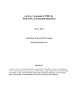
1
USER MANUAL ShuttleSoft 1. List of parts o ShuttleSoft installation CD o USB hardkey dongle o LabView Vison runtime license o uEYE USB camera C-mount lens USB cable Tripod adapter Bracket Software CD o DAQ-S instrument Adapter cables, qty. 4 DO-SET for oxygen control, qty. 2 OR TMP-SET for temperature control, qty. 2 OR pump for salinity control, qty. 4 o o o OXY-REG for oxygen measurements, qty. 2 OR TMP-REG for temperature measurements, qty. 2 OR WTW COND 3310 instruments for salinity measurements, qty. 2 o Flow though probe vessel, qty. 2 o User manual Page 1 of 34 2. Contents 1. List of parts ........................................................................................................ 1 2. Contents ............................................................................................................ 2 3. Installation procedure .......................................................................................... 3 3.1 General........................................................................................................... 3 3.2 ShuttleSoft software for Windows....................................................................... 4 3.3 Connection overview salinity............................................................................ 13 3.4 Connection overview temperature .................................................................... 14 3.5 Connection overview oxygen ........................................................................... 15 3.6 uEye USB camera........................................................................................... 16 3.7 DAQ-S instrument .......................................................................................... 17 3.8 WTW 3310 Cond instrument (salinity only)........................................................ 18 4. Experiment set up ............................................................................................. 20 4.1 Tank............................................................................................................. 20 4.2 Salinity ......................................................................................................... 21 4.3 Temperature ................................................................................................. 22 4.4 Oxygen ......................................................................................................... 23 5. Using ShuttleSoft .............................................................................................. 24 5.1 Start up ........................................................................................................ 24 5.2 New experiment............................................................................................. 27 5.3 Details .......................................................................................................... 28 5.3.1. General .................................................................................................. 28 5.3.2. File Menu................................................................................................ 30 5.3.3. Settings Menu ......................................................................................... 30 5.3.4. Calibration Menu ..................................................................................... 31 5.3.5. Log Menu ............................................................................................... 31 5.3.6. Help Menu .............................................................................................. 31 6. TroubleShooting ................................................................................................ 32 6.1 DAQ-S connection failure ................................................................................ 32 6.2 Relays unresponsive ....................................................................................... 34 6.3 uEye camera connection failure........................................................................ 34 Page 2 of 34 3. Installation procedure 3.1 General ShuttleSoft is a piece of PC software for Shuttle Box experiments ShuttleSoft require Windows XP or Vista running on a PC with an Intel Pentium IV processor of 1 GHz and 1 GB RAM or better. We recommend monitors with a minimum resolution of 1024x768 pixels. ShuttleSoft requires a mouse with a scroll button. Three free USB ports are required on your PC. One for connecting the DAQ-S instrument, one for the digital video camera and one for the dongle. If using WTW COND 3310 instruments for pref. salinity experiment two additional USB ports are required. The ShuttleSoft software finds the position of the experiment animal on the principle of contrast between the object and the surroundings frame-by-frame. The software determines if the animal is in the INCREASING part of the Shuttle box tank part or DECREASING. This is defined by the user. The ShuttleSoft software activates and deactivates solenoid valves/pumps connected to digital relays on the DAQ-S instrument. This way water quality can be controlled automatically depending on animal real-time positions. The software will save all input data and calculated values to an Excel data file. Page 3 of 34 3.2 ShuttleSoft software for Windows The following steps will explain how to install ShuttleSoft on your computer. 1. Insert the CD labelled ShuttleSoft and wait until you see Screen 1. If you do NOT see the screen, browse the CD and double click on the icon labelled ShuttleSoft.exe. Screen 1 2. Click Next to start installation of ShuttleSoft. Screen 2 Page 4 of 34 3. Select destination directory for ShuttleSoft and LabView drivers and then press Next. Screen 3 4. If you accept the License Agreement, please select “I accept the License Agreement(s)” and then press Next. Screen 4 5. Click Next. Page 5 of 34 On Screen 5 the status of the installation is shown. The installation may take a while. Screen 5 Screen 6 6. Click Next to end installation of ShuttleSoft and activate the product. This activation requires an internet connection. Page 6 of 34 7. Choose automatic activation and click Next to activate the software. Screen 7 8. Enter the serial number found on the LabView Vison runtime license card. Then click on Next. Screen 8 Page 7 of 34 9. Fill out the fields with your information, when done click Next. Screen 9 10. If activation was successful Screen 10 appears. Click on Finish to end the activation. Screen 10 Page 8 of 34 11. Now install drivers for the hardkey dongle. When Screen 11 appears, click Next. Screen 11 12. Select supported language, and click Next. 13. Click Next without changing any options. 14. Click Next again after you have accepted the summary of the installation. 15. When installation is done, click Next again. 16. Click Finish to end installation of the WiBu drivers. Page 9 of 34 17. Now drivers for the uEye USB camera will be installed. When Screen 12 appears, click Next. Screen 12 18. Select unpack and remove, and then click Next. Screen 13 Page 10 of 34 19. Wait for the files to be unpacked. The setup screen will appear when done. Screen 14 20. Select “Install driver”. 21. Choose language and then click Next. 22. When Screen 15 appears click Next. Screen 15 Page 11 of 34 23. When Screen 16 appears select Complete and then click Next. Screen 16 24. Choose a destination and then click Next. 25. Select a program folder and then click Next. 26. Click Install to start the installation. 27. Select the additional features you want, then click Next Screen 17 28. Select Click Finish to end the installation of the uEye software package. 29. Remove the CD labelled ShuttleSoft from your CD drive. 30. Restart the Computer. You have now finished the installation of all the software. Page 12 of 34 3.3 Connection overview salinity The following diagram shows how to connect the instruments and devices used for running a preference salinity experiment. Page 13 of 34 3.4 Connection overview temperature The following diagram shows how to connect the instruments and devices used for running a preference temperature experiment. Page 14 of 34 3.5 Connection overview oxygen The following diagram shows how to connect the instruments and devices used for running a preference oxygen experiment. Page 15 of 34 3.6 uEye USB camera 1. Connect the uEye USB camera to the PC. After a few seconds the software installation will start automatically. 2. Click on “Install the software automatically (Recommended)” and then on Next. 3. Click on continue anyways. 4. Click on Finish. 5. Open the uEye camera manager by clicking StartAll ProgramsIDSuEYE Screen 18 6. If installation was successful, the uEYE camera is now shown here. 7. Mount the lens on the uEYE camera. 8. The uEYE camera is now ready for use with ShuttleSoft. Page 16 of 34 3.7 DAQ-S instrument 1. Connect the DAQ-S instrument to the PC. After a few seconds the software installation will start automatically. 2. Click on “Install the software automatically (Recommended)” and then on Next 3. The drivers will now be installed, when done click Finish. 4. Open the Measurement and Automation Explorer (MAX) by clicking StartAll ProgramsNational InstrumentsMAX Screen 19 5. If installation was successful, the USB-6008 DAQ card is now shown here. Page 17 of 34 3.8 WTW 3310 Cond instrument (salinity only) 1. Connect the WTW Cond 3310 instrument to your PC. After a few seconds the software installation will start automatically. 2. Click on “Install the software automatically (Recommended)” and then on Next. If Winows cannot find the drivers, please insert the WTW disc. 3. The drivers will now be installed, when done click Finish. 4. Repeat step 1-3 for the second WTW Cond 3310 instrument. Page 18 of 34 The WTW 3310 Cond needs to be calibrated before starting an experiment. Please follow the instructions in the WTW user manual of the instrument. The user manual can be found on the CD delivered together with the instrument. Before starting ShuttleSoft the WTW instrument serial interface has to be set, to secure export of data. 1. Press ENTER in 2 seconds and choose System. Then press Reset and choose Yes. 2. Then press F1 and choose Reset. Press Yes. 3. Press the M button several times until the instrument measures in Sal. 4. Press the F2 button in 2 seconds. Choose Interval and set it to 1 s. 5. Now choose Continue and press ENTER. The WTW instrument will now start sending data out every second via the serial interface (RS232). DO NOT CHANGE ANY SETTINGS, LIKE LANGUAGE, SEND ID, UNIT ETC. ELSE THE COMMUNICATION BETWEEN THE INSTRUMENT AND SHUTTLESOFT WILL FAIL. Page 19 of 34 4. Experiment set up 4.1 Tank Set up the shuttle tank system as shown on the diagram below. Make sure that the flow direction is correct! If the flow into the shuttle tank is too high, either place a tube clamp on the output side of each pump hose, or lower the position of the buffer tank relative to the Shuttle box tank. Page 20 of 34 4.2 Salinity The diagram below shows how to connect buffer tanks with water reservoirs (not supplied) containing high and low saline water. The fittings in the middle of each buffer tank are used as overflows. Page 21 of 34 4.3 Temperature The diagram below shows how to connect the buffer tanks with the cooling/heating baths. Page 22 of 34 4.4 Oxygen The diagram below shows how to connect the buffer tanks with O2/N2 gas bottles. The air stones need to be placed into down at the bottom of the buffer tanks. The remaining fittings on each buffer tank are connected together. Page 23 of 34 5. Using ShuttleSoft 5.1 Start up Start ShuttleSoft by clicking StartAll ProgramsShuttleSoftShuttleSoft. If the USB hardkey dongle is not connected to the PC, an error dialog box pops up, see Screen 20. Screen 20 Connect the USB hardkey dongle to your PC and wait for the device to be recognized, then click on Retry. Then ShuttleSoft will ask the user of what kind the input is. Screen 21 If choosing preferred Salinity experiment and WTW Cond 3310 the following screen will apear where user is asked to choose the right COM ports for the two WTW Cond 3310 instruments. Page 24 of 34 After choosing COM port, press Connect and ShuttleSoft will try to establish communication with the two WTW 3310 Cond instruments. If connection was successful, the OK button gets available, and the user can continue the initialization by pressing OK. Now Screen 22 will now appear. Screen 22 Page 25 of 34 ShuttleSoft will connect automatically to the first uEye camera found. If no uEye camera is found, ShuttleSoft will detect all USB cameras connected to the PC and ask the user which camera should b used. If no USB camera is found connected to the PC, the following box will appear. The next step is that ShuttleSoft looks for a DAQ-S instrument connected to the PC and is named dev1. If a DAQ-S instrument is connected to the PC but ShuttleSoft has problems finding it please look in the chapter TroubleShooting. If ShuttleSoft has found the DAQ-S instrument, the initialization is done and images from the camera are now seen on the screen. The user can now draw a mask (avoid analysis of areas outside Shuttle Box), INCR and DECR zones, calibrate pixels into units of measure and/or calibrate the input signals. Finally the user can start logging experiment data to an Excel file. To zoom a picture place the mouse over the picture and use the scroll button to zoom. If ShuttleSoft is enlarged, the buttons and graph will remain at the same size, but the image is enlarged. Page 26 of 34 5.2 New experiment Click Binary and use the vertical threshold bars to find the animal inside the Shuttle Box. Start by choosing a narrow range (short distance between the 2 bars) and then use the right hand side slider to scan the image for your animal. If necessary use the filter options found in SettingsFilter to remove irrelevant pixels in the picture. When done click Binary again to view unmodified images. To avoid tracking any moving objects outside the Shuttle Box, click SettingsMask to draw a mask excluding areas for analysis. When done click OK. Now click CalibrationPixel and use the mouse to draw a line along an axis of a known distance in the image. Then enter the distance and unit for the line. The pixel-to-meter ratio is now calculated. Click OK when done. Now ShuttleSoft will find the position of the animal, and calculate its velocity and the distance moved. Click SettingsZones, and draw two zones, one for each of the two Shuttle Box tanks. In the red zone (INCR) oxygen/temperature/salinity will increase whenever the animal is present. In the blue zone (DECR) oxygen/temperature/salinity will decrease. Any areas outside the two zones will be referred to as OFF zone. We recommend leaving a narrow space between the two user-defined zones, in order to avoid errors or misinterpretation associated with animals taking positions in the pass way between the two tanks for prolonged periods of time. When done click OK. For every second, ShuttleSoft will now determine the animals x-y (2D) zone position and log how often it enters a new one. Click CalibrationOxygen/Temperature/Salinity to do a two-point calibration, converting analog inputs on channels IN A and IN B into % air saturation or °C (NB! If using WTW Cond 3310 this is not necessary). Refer the OXY-REG/TMP-REG/WTW Cond 3310 user manual for further instructions on how to calibrate or service probes. Then decide if input IN A should be used for monitoring oxygen/temperature in the (red) INCR zone or the (blue) DECR zone. Do the same for IN B. When done click OK. Now ShuttleSoft will show oxygen/temperature/salinity values for the zone (or tank) in which the animal is present. During times when the animal is in OFF zone, an average between the oxygen/temperature/salinity values in INCR and DECR zones will be calculated. Now set up the difference in oxygen/temperature/salinity that the system should maintain between the two zones – we call it the Delta ± Hysteresis values. Depending on the animals position, the valves/pumps will be activated/deactivated to keep a set difference (Delta) between the two zones. During times when the animal is in the OFF zone, the system will maintain the oxygen/temperature/salinity levels in the two zones recorded prior to entering the OFF zone. To start writing experimental data to a file, click LogStart. Then choose a destination for the data file. To stop logging, click LogStop. To exit ShuttleSoft, click FileExit. Page 27 of 34 5.3 Details 5.3.1. General INCR O2 / INCR temp. / INCR sal. This field indicates the current O2 saturation/temperature/salinity for the INCR zone. DECR O2 / DECR temp. / DECR sal. This field indicates the current O2 saturation/temperature/salinity for the INCR zone. Object zone This field indicates whether the object is in INCR, DECR or OFF zone. Object O2 / Object temp. / Object sal. This field indicates the current O2 saturation/temperature/salinity that the animal is exposed to. INCR visits This field indicates how often the object has entered the INCR zone. This value will be set to 0, when user starts logging. DECR visits This field indicates how often the object has entered the DECR zone. This value will be set to 0, when user starts logging. Distance In this field the distance moved by the object is calculated. The unit of measure can be set via the menu for pixel to meter calibration. This value will be set to 0, when user starts logging. Velocity In this field the velocity of the object is calculated once per second. Please note that the object has to move at least a half pixel length from frame to frame to be obtained as a movement. Threshold bars Use the bars to set the threshold used to find the binary picture. On the left bar it is possible to set the range of the threshold values. The right bar is to move both sliders. Example: The two sliders on the left are set to 40 and 70 and the red indication is between them. Every pixel that has a value between 40 to 70 will be coloured red and all other pixels will be coloured black. The slider on the right bar will stay on 55. Now the user moves the slider to 110. The red indication on the left bar will now be between 95 and 125. Page 28 of 34 Delta Use this field to set the maximum difference in oxygen saturation between the 2 zones. Example: Oxygen saturation is 80% in INCR zone, and 70% in DECR zone. Delta is set to 15. Now if the animal enters the DECR zone, ShuttleSoft will start decreasing the oxygen value in this zone. When the oxygen saturation drops below 65%, and Delta thus exceeds a value of 15% air sat., ShuttleSoft will also start decreasing oxygen saturation in the INCR zone to maintain a maximum difference of 15% air sat. Once the Delta value is <15% air sat. the bubbling of nitrogen gas will stop again. Hysteresis Use a hysteresis value greater than 0 to ensure that the relay does not flicker on the sharp edge of the Delta value, since this might cause a malfunctioning of the solenoid valve. The hysteresis value will also determine upper and lower limits maintained by the system while the animal is in OFF zone. Example: Oxygen saturation is 80% in INCR zone, and 70% in DECR zone. Hysteresis is set to 1%. The animal enters OFF zone between the two tanks and stays there for a while. Due to equilibration with the atmosphere, oxygen values will rise in both tanks. Once the oxygen saturation in DECR zone reaches 71%, ShuttleSoft will activate a relay to open the valve blowing nitrogen into this tank until saturation is back to 70%. Mask Use this button to toggle between unmodified video images and masked images. Binary Use this button to toggle between unmodified video images and thresholded images. Trace Use this button to enable/disable a trailing trace from being shown behind the moving animal and set the duration of the trailing trace in seconds. RE1 This diode indicator gives the relay status for relay 1. On relay 1 the oxygen valve/heating pump for the INCR zone must be connected. RE2 This diode indicator gives the relay status for relay 2. On relay 2 the nitrogen valve/ cooling pump for the INCR zone must be connected. RE3 This diode indicator gives the relay status for relay 3. On relay 3 the oxygen valve/ heating pump for the DECR zone must be connected. RE4 This diode indicator gives the relay status for relay 4. On relay 4 the oxygen valve/cooling pump for the DECR zone must be connected. Log This diode will blink while logging. When moving the mouse over the diode, the actual saving path will be shown. Page 29 of 34 Image Here the video images from the camera is shown. When maximizing ShuttleSoft on your PC monitor, the image will scale accordingly. Move your cursor over the image and zoom/unzoom by using the scroll button on your mouse. Oxygen vs. time / Temperature vs. time graph On this graph oxygen/temperature values are shown, e.g. reading from the inputs IN A and IN B. The left scale is for the INCR zone (red plot) and the right scale is for the DECR zone (blue plot). Interval [min] Use this field to set the X axis time interval for the graph. 5.3.2. File Menu Exit On exit the software will close the camera input and save all settings and then close ShuttleSoft. 5.3.3. Settings Menu Mask Opens a dialog box, where users may create a mask to avoid analysis outside areas of interest. Use either one of the upper buttons to draw a closed figure in the image. Then decide if you want to include or exclude the enclosed area by pressing either one of the two upper buttons in the lower group of buttons. Below there is a button to undo the last step, and one to clear the entire mask and start over. Also it is possible to invert the drawn mask. Created masks can be saved or loaded as bitmap files. When maximizing the dialog box, the image will scale. When moving the mouse over the camera, it is possible to zoom/unzoom the image via the scroll button on the mouse. Zones Opens a dialog box where users may define the INCR and the DECR zone. Start by drawing a closed figure. Then decide if the closed figure should be used as INCR or DECRS zone by clicking either on the I-button or the D-button. Then draw a next closed figure and choose this as the missing zone. Drawn closed figures can be saved or loaded as bitmap files. When maximizing the dialog box, the image will scale. When moving the mouse over the camera, it is possible to zoom/unzoom the image via the scroll button on the mouse. Camera Opens a dialog box where users may set the video settings of the camera. Filter Opens a dialog box where user may set the filter options. Page 30 of 34 5.3.4. Calibration Menu Calibration Opens a dialog box where users may convert image pixels into mm, cm or metres. Change the length and/or position of the green line to match any known distance in the image, e.g. a ruler. The length of the green line will show. Then choose the desired unit of measure and enter the known distance. A pixel ratio will now be calculated and used for all calculations. When maximizing the dialog box, the image will scale. When moving the cursor over the image, it is possible to zoom/unzoom the image via the scroll button on the mouse. Oxygen Opens a dialog box where users may calibrate/convert the input signal from the DAQ-S instrument to %air sat/°C. The calibration is a 2-point calibration. Place the tip of the probe connected as input IN A in a known solution and wait for it to stabilize. Press Lock LO and write the %air sat./temperature value in the LO calibration field. Now place the tip of the oxygen probe in a second known solution and wait for it to stabilize. Press Lock HI and write the %air sat./°C value in the HI field. Use a >>20% difference between the two calibration solutions to maximize the accuracy of oxygen/temperature measurements. Finally, choose if the input should be used as input for INCR or DECR zone. Do the same for input IN B. 5.3.5. Log Menu Start logging data Opens a note field, where users may write notes for the experiment. Then a file prompt opens and user must choose a destination for the data file. When pressing OK, data logging starts. Stop logging data Stops logging data to the data file and closes it. 5.3.6. Help Menu About This menu will open a dialog box, showing the version number of the ShuttleSoft software and contact information for Loligo Systems. Page 31 of 34 6. TroubleShooting 6.1 DAQ-S connection failure Screen 23 The error shown on Screen 23 occurs, when the NI-USB 6008 DAQ card has no properly connection to the PC. This error can occur in 2 ways. Name is not “dev1” To change the device name, open the NI program called Measurement & Automation (look for desktop icon). The following example on Screen 24 shows a simulated device named as “dev1”. The NI-USB 6008 DAQ card is registered as “dev2” Page 32 of 34 Screen 24 Right click with mouse on the “dev1”, and choose rename, or press F2. Change the name to something different than “dev1”. In this example the name is changed to “dev1simu”, see Screen 25. Screen 25 Now change the device name of the NI USB-6008 DAQ card to “dev1”. The DAQ-S instrument should now work properly with ShuttleSoft. Page 33 of 34 Screen 26 Another USB device was improperly removed If an USB device, like a USB memory stick, is not properly removed, while ShuttleSoft is running, there can be a connection problem with the DAQ-S instrument. To solve this problem, close ShuttleSoft. Then disconnect the USB cable between the PC and the DAQ-S instrument. Wait 30 seconds. Then connect the cable and wait. When the green diode on the front side of the DAQ-S instrument is flashing, the connection is reestablished. ShuttleSoft can now be opened again. 6.2 Relays unresponsive Make sure the DAQ-S instrument is connected with a power cable, and the Power button is ON. 6.3 uEye camera connection failure Make sure that no other program is using the uEYE camera while using it in ShuttleSoft. Only one software program at the time can acquire data from the camera. Page 34 of 34