1
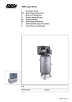
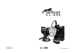
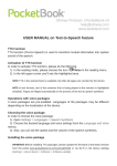
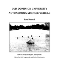
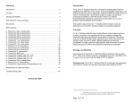
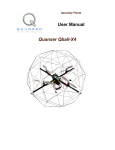
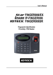
Autonomous Underwater Vehicle Programming
and System Interfacing
Semester:
Summer 2009
Proposed Dates:
13 May – 7 August
Credit Hours:
3
Name:
Jacob H. Cox Jr
Student ID:
1743498
Sponsoring faculty:
Dr. Michael Gustafson
Name of supervisor:
Dr. Nan Jokerst
Phone:
(706) 951-9741
Email:
[email protected]
Autonomous Underwater Vehicle Programming and System Interfacing
Jacob Cox
[email protected]
Pratt School of Engineering, Duke University
Summer 2009 (13 May – 7 August)
Abstract—the Duke Robotics club hopes to compete in the annual International Autonomous
Underwater Vehicle (AUV) competition next year. To this end, a project was undertaken by the
author to develop the software interfaces required by the AUV to control its thrusters and steer
the AUV in a remote control setting. This work provides a dynamic link library (DLL) file that
successfully interfaces LabVIEW, a graphical programming language, with the C code based
hardware drivers of the PCM-MIO Digital-to-Analog card (DAC). Furthermore, the author
provides a detailed overview of the components comprising the AUV along with a newly revised
wiring schematic showing how the AUVs electrical components are now interfaced.
1. Introduction
In July 2007, the Duke University Robotics Club competed in the 10th annual International Autonomous
Underwater Vehicle competition held in San Diego, California [9]. With their robot, named Scylla, the
robotics team had high expectations for a top three finish, as was the case during the previous year’s
competition with their earlier model robot, named Charybdis. Initial practice runs also contributed to the
team’s hopes as they successfully completed enough tasks to lock-in 2nd and 3rd place rankings [9].
Unfortunately, an unforeseen and undiagnosed communication fault, along with a “fried” acoustics
board, ultimately prevented the team from competing. This was the last time Duke University competed
in this competition [9].
In order for the AUV to successfully compete in the above mentioned tournament, held annually, the
AUV must meet several requirements. These requirements include having the AUV pass through an
underwater gate, land on a beach and set off a light beacon, follow a dashed line, mark a target, identify
a brief case containing an acoustic beacon, retrieve the briefcase, and move to a specified location for
the completion of the event [8] [9].
Seeing this absence from the competition as a project opportunity, this author submitted a project
proposal offering to research, program, and implement the programming code required to interface
hardware drivers for the AUV and document the results. This project was planned to be conducted
alongside other team members working on various other aspects of the robot, including acoustics,
vision, and positioning. While the Duke University Robotics club greatly wished to compete in the
International Autonomous Underwater Vehicle tournament this year, the summer team quickly
discovered that there were simply too many hurdles to overcome and instead set up preparations to
compete in next year’s tournament.
2. General Overview of Work Conducted
In the spirit of innovation, the summer robotics team chose to implement its control system in
LabVIEW, a graphical programming language, on a Windows XP platform. Several factors contributed
to this decision. One is that numerous companies are using LabVIEW in commercial markets, and the
use of this software provided team members with an excellent familiarization of this software.
Additionally, Duke University owns full license to this software, so it provided the club with a no cost
software option. Windows XP was chosen because it supported the LabVIEW software and was readily
available in the lab. Finally, LabVIEW provides numerous tools for working with visual and digital-toanalog card (DAC) components.
Unfortunately, initial discoveries revealed that numerous hardware components had been damaged over
the previous two years, and thus prevented initial software development. Such components included the
Epic NANO PC-104 single board computer (SBC), the pressure sensor, the acoustic boards, the digital
to analog converter (DAC), and the robots internal wiring. Additionally, little documentation was
discovered to allow current project members to further the efforts of the previous year’s group. As a
result of these early setbacks, this author’s focus quickly turned to developing the schematic for the
robot’s electronics and circuitry and then interfacing the actual components. More about this
development will be discussed in the section 3 of this paper.
While investigating the AUV’s component operability and use, the author evaluated the following
components and documented their use.
Table 1. Listing of AUV Components.
Component Listing
No. Component Listing
NANO-4386A Single Board Computer
1 32 gb Compact Flash Card (Type 1)
WinSystems PCM-MIO-G (DAC Card)
1 Teledyne ExplorerDVL
TC4013 Hydrophones
3 FDC60-24D12 DC/DC Converter
tecnadyne Model 250 DC Brushless Motors
5 HMR3000 Honeywell magnetic compass
tecnadyne ISO-4 Cards
2 Crydom Solid State Relay
Thunder Power RC Pro Lite MS 4s4pl 8000mAh LiPo Battery
4 Pressure Sensor (TBD)
uEye 2.0 USB Cameras
2
No.
1
1
2
1
2
NA
2a. Epic Nano 4386A-R10 PC/104 Single Board Computer
The Epic Nano 4386A-R10 PC/104 Single Board Computer (SBC) used for this project was riddled with
problems from the onset of this project. It was subject to intermittent faults causing it to reboot at
random intervals. Additionally, the 8 GB Compact Flash card, which holds the Windows XP operating
system, had approximately two gigabytes of corrupted memory requiring a reinstallation of the operating
system. Trouble shooting this board was also time intensive as the AUV team could not alleviate the
constant rebooting. Early indications pointed to the PC/104 board itself as the problem; however due to
the boards expense and the team’s inexperience with single board computers, a choice was made to
eliminate all other possibilities before ordering a new board. As a result, the board remained an ongoing
frustration for nearly five weeks as troubleshooting continually failed to locate the fault on the board and
smaller components were replaced—those being a new Compact Flash Card, a system RAM chip, and a
battery.
Note, that for lab use, the PC-104 is powered by an ATX power source with its green and black wires
shorted together. The ATX power source is standard in many personal computers. Figure 1 shows the
PC-104 connected to a hard drive and DVD player/recorder.
Figure 1. Epic Nano 4386A-R10 PC/104 Single Board Computer (SBC).
Eventually, the CPU was transferred to a new board, and this eliminated the rebooting faults; however,
upon installing Windows XP, a page fault developed. Because of this and the development of IDE
problems, another week was spent unsuccessfully attempting to install LabVIEW. At one point, the PC104 Board was even turned over to Duke IT to see if they could install the LabVIEW software. After a
week, Duke OIT also gave up on this endeavor.
The fix ended up being a complete reinstallation of the Windows XP operating system, after connecting
a DVD and external Hard Drive and reconfiguring the SBC’s BIOS. This attempt resulted in a fully
functional O/S, and LabVIEW was then installed. Unfortunately, the 8 GB Compact Flash did not
possess enough memory to support the 6 GB of space required by LabVIEW and the other 1.7 GB
required by Windows XP to operate. Initially, the AUV team thought the CF cards could only be type II,
which is a much more expensive CF card (around $229.00) with a maximum storage capacity of 16 GB.
Fortunately, an AUV team member discovered that type I cards were interchangeable in Type II CF
sockets and that the PC-104 board would support a Type I CF card as well. As a result, the 32 GB CF
card for the project was purchased. With the new card, the O/S and required software was finally
installed. Ultimately, the most needed requirement for this phase of the project was a lot of patience and
a better understanding of the system BIOS configurations, along with the complete replacement of the
PC-104 board—minus the CPU.
2b. PCM-MIO Digital-to-Analog (DAC) Card.
The PCM-MIO board used for this project has 8 digital-to-analog outputs and 16 analog-to-digital
inputs. It also provides a sample rate of 85 ksps. Amusingly enough, this is the one piece of equipment
that the AUV team was told was inoperable that actually worked. After reading the operation manual for
this piece of equipment, the author determined that the address jumpers on the DAC card were
misconfigured. However, once these jumpers were setup
properly, the PCM-MIO was recognized by the PC-104
SBC. The only real problem with this DAC card is that
WinSystems doesn’t provide LabVIEW drivers for its
hardware. This requires that a Dynamic Link List (DLL)
be written in Visual C++ to call functions written for the
C code driver software provided with the PCM-MIO
board. This DLL is in turn called by LabVIEW using its
Call Library Function (CLF). More about this DLL and
LabVIEW will be discussed later in the implementation
section.
2c. Crydom Relay
Figure 2. PCM-MIO Digital-to-Analog (DAC) card
Figure 3. Crydom Relay.
The current system as it now stands requires three D2D12 relays to create a break between power
sources and their intended destinations. Whenever a voltage of 3.5 VDC or greater is applied to its input,
the relay allows the Output nodes to pass current. Note that it is imperative that the output terminals be
connected appropriately as the relay will not work correctly if the positive and negative terminals are not
connected to each other respectively. If connected backwards, the relay will allow current to flow
through the output terminals regardless of the input voltage. Yes, this comes from experience! For the
AUV, one relay controls the power provided to the PC-104 SBC. This power is continuous so long as
the AUV power switch is closed. The second relay allows the Digital-to-Analog (DAC) card to control
instrument power provided to motors and control logic. This is discussed further in the implementation
section of this paper when the wiring schematic is discussed. Finally, a third relay controls the power
provided to the motors. This is also discussed with the wiring schematics in the implementation section.
2d. FDC60-24D12 DC/DC Converter
The FDC60-24D12 DC/DC Converter provides the AUV circuitry
with a steady supply of +12 VDC power. This converter was
mounted on a circuit card by previous AUV teams. Unfortunately,
the PCB express schematics, detailing the mounting board layout,
was not available. This forced the author to test each of the outputs
of the power board shown to the right in Figure 4 in order to verify
the output values when +30 VDC is applied. Having determined that Figure 4. FDC60-24D12 DC/DC Converter
all outputs of these boards is +12 VDC, the author included two
DC/DC converters in the new AUV wiring. One converter provides a steady +12 VDC to the PC-104
SBC, and the other DC/DC converter provides and intermittent +12 VDC to the control logic of the
motors as determined by the AUV’s control system.
2e. The ISO-4 Card.
The ISO-4 card is manufactured by Tecnadyne—
this is the same manufacturer of the thrusters used
for this AUV—and provides isolated +/- 5 VDC
control signals and +12 VDC instrument power
for up to four Tecnadyne motors. The AUV
utilizes two ISO-4 cards to provide instrument
power, instrument ground, and a control signals
to each of the AUV’s six motors. These cards are
in turn connected to a +12 VDC power source,
provided by the AUV’s DC/DC converter, and
six analog control signals, provided by the PCMMIO DAC Card. The ISO-4 cards are
implemented as a precautionary measure.
According to the documentation provided by
Tecnadyne [4], feedback from motors is capable
of damaging the control system’s DAC Card if
not protected. The ISO-4 cards provide the
desired protection from these feedback signals by
creating isolated circuits for each motor.
Figure 5. The ISO-4 Card.
2f. Model 250 DC Brushless Thrusters
The AUV utilizes six motors for steering and propulsion. Note that the robotics club only owns five
thrusters, and that one has been borrowed in competitions past. Each motor has five inputs (pins 1-5)
and one output (pin 6). Pin 1 attaches to a black wire and provides the ground for the thruster’s power
source. Pin 2 attaches to a white wire and provides up to a +150 VDC, 1.9A power input. In the case of
this AUV, the power is provided from two Power RC Pro Lite MS 4s4pl 8000mAH LiPo Batteries [10]
that provide approximately 30 VDC +/- 1 VDC. Pin 3 attaches to a red wire and provides the instrument
power ground. Pin 4 attaches to a green wire and provides the thruster with its +12 VDC Instrument
power. Pin 5 is attached to an orange wire and provides the thruster with its +/- 5 VDC control voltage.
It is important to note that this voltage should always rise and fall with some unit of time and never step.
Figure 6. Model 250 Tecnadyne Thruster [4].
Table 2. Model 250 Pin Connections.
For DC voltage values between -0.5 V and +0.5 V, the thrusters will remain still. For all voltages in
between, the thrusters obtain a modified thruster output [4]. It is also important to note that control
signals must be electrically isolated from the thruster’s power source [4]. Additionally, the control signal
must also be held at 0v when thrusters are stopped as opposed to creating an open circuit [4]. Another
important note is that, when controlling the thrusters, it is important to use a linear ramp in lieu of a step
function for the control signals. The recommended control signal ramp is 10 milliseconds / volt
according to the Tecnadyne Application Note AN601 [4] . More importantly, the control voltage should
not be allowed to switch from a positive voltage to a negative voltage without first asserting 0 VDC and
allowing the thruster to come to a full stop. Pin 6 attaches to a brown wire and provides the +5V analog
speed output. For the analog control systems, the thruster runs forward at full speed for +5 VDC and
full reverse at -5 VDC. Table 2 shows the pin out.
2g. Thunder Power RC Pro Lite MS 4s4pl 8000mAH LiPo Batteries
The six Tecnadyne DC brushless motors and all circuitry in the AUV are powered by two sets of two
Thunder Power RC Pro Lite MS 4s4pl 8000mAH LiPo Batteries [10] connected in series. Each battery
provides approximately 14.8 V DC and provide a combined
voltage of 29.6 VDC per set. Each set is connected to an
isolated circuit. Additional safety measures for these circuits
include a fast blow type fuse with a current rating 50% higher
than the steady state current allowed for by each of the motors
[4]. Additionally, a 450 uF capacitor is placed in parallel to the
positive and negative terminals of the battery set providing
direct power to the motors in order to protect against voltage
spikes created by sudden voltage changes in the motor
Figure 7. Thunder Power Pro Lite Battery [10].
windings.
2h. ExplorerDVL (Doppler Velocity Logger)
Figure 8. Explorer DVL.
3. Input Power and Communication Interface
The ExplorerDVL in the AUV uses 4 x RS232 Table
Connector (J3) Wiring.
communication protocols to communicate with the
PC-104 board. A combination of other protocols is also
possible, but future AUV teams are referred to the
ExplorerDVL Operation Manual [5] for further
guidance on those protocols. For Power, the DVL
requires a DC supply between +12 VDC and +28
VDC, which is provided by the AUV’s onboard DC
Batteries. This DVL also comes with its own utility
program BBTalk. This software is used to help set up,
use, test, and trouble-shoot the ExplorerDVL.
However, this Software also requires a Windows XP
operating system—see [5] for additional windows
compatible O/S. In order to test the DVL, the reader is
again referred to page 15 of [5]. In order to properly
mount this device, the operation manual recommends
mounting the “transducer head with Beam 3
(instrument y axis) rotated 45 degrees relative to the
ship forward axis.” It is also important to protect the transducer from damage as this will result in a
diminished performance or inoperability of the ExplorerDVL. The pin out for the J3 plug of the DVL is
shown Table 3.
2i. HMR3000 Honeywell Magnetic Compass
The HMR3000 Honeywell Magnetic compass provides pitch, roll, and heading outputs for navigation
[13] and needs to be “strapped” to the DVL. It was obtained this summer when a group member
determined that it was needed so that the DVL mentioned above could work properly. For further
information about this compass the reader is referred to the HMR3000 information sheet [13].
2j. uEye USB 2.0 Cameras
For vision, this AUV incorporates two uEye USB 2.0
cameras. These cameras come with a rugged housing
making them great for industrial or robotic use. For the
AUV, one camera is mounted facing forward while the other
is mounted facing the bottom of the AUV. Together, these
cameras are used to track objects either on the bottom of a
pool or ahead of the vehicle. Another aspect of these
cameras making them convenient for AUV use is their
LabVIEW drivers. Sample programs are also provided to
assist with the development of more specialized
applications. For more information about these cameras, the
reader is referred to the product’s user manual [6].
Figure 9. uEye USB 2.0 Camera [6].
2k. TC4013 Miniature Reference Hydrophone
In order to triangulate an acoustic beacon, the AUV has three
miniature TC4013 hydrophones. These omnidirectional
hydrophones boast a high sensitivity to frequencies ranging
from 1 kHz to 170 kHz [12]. Additionally, they do not
require that any power be applied to them directly. However,
they do require signal amplification in order for the signals
they detect to be read by the AUV’s DAC card. Currently, no
amplification hardware has been developed. In past years, not Figure 10. TC4013 Miniature Reference Hydrophone.
only was an op-amp used, but a band-pass filter and hardware
requiring its own drivers was developed. LabVIEW, the software used for this project, has special
program features that make implementing a bypass filter in software much more feasible for this AUV.
2l. Software.
The software used for this AUV includes Windows XP home edition, LabVIEW, Microsoft Visual C++
[7], and TeamViewer. Windows XP was chosen due to its compatibility with the LabVIEW software
package and the AUV team’s familiarity with the O/S. For the most part, software was chosen based on
its ease of use, price, and familiarity.
Several factors contributed to the team’s choice of LabVIEW. For instance, it is used by industry
worldwide for robotics applications and is praised as a powerful and flexible design tool [2].
Additionally, Duke University owns a full license for the software, so its use added no additional cost to
the development of the AUV’s control system. With LabVIEW being a graphical programming
language, the team believes that this software provides a more intuitive way of understanding the code
produced by other programmers. LabVIEW even provides a trace option that allows users to follow the
flow of the code to see how the program performs its functions, which provides a visual means for
program debugging. Thus, the author believes that the use of LabVIEW will make it easier for work
developed in LabVIEW to be understood by future AUV project teams. Therefore, LabVIEW is seen by
the team as a worthwhile endeavor for the AUV project and software familiarization.
Still, despite the rising popularity of LabVIEW and its use in industry, one setback initially encountered
by the AUV team involved a lack of support by hardware vendors to provide LabVIEW drivers for their
hardware. In the case of this project, the WinSystems PCM-MIO DAC card was chosen due to its eight
analog outputs, sixteen analog inputs, and sample rate of 85 ksps; however, no LabVIEW drivers are
provided with this hardware and LabVIEW is unable to utilize this card directly. As a result of this
limitation, Visual C++ was chosen to develop the Dynamic Link Library (DLL) files required to use the
drivers that came with the PCM-MIO DAC card. Fortunately, Microsoft offers a free download of
Microsoft Visual Studio for students, and it was chosen for its ability to easily generate DLL files.
Finally, TeamViewer—remote login software—was chosen in order to access the AUV robot from other
computers over the network for testing and as an option for remote control. TeamViewer is available
from download.com and is free for non-commercial use.
3. Implementation
Due to the lack of documentation provided by previous AUV teams, this project quickly turned to
finding and verifying the operability of all equipment already on hand and documenting how all of these
components were met to be interfaced. Several other hurdles also quickly presented, ranging from
mislabeled wire interfaces to an inoperable PC-104 SBC, as this project progressed.
The first obstacle required that the AUV be completely rewired due to mislabeling of connectors and the
arrival of a new chassis. Since components were being reused from the old chassis, all of the required
parts had to first be removed before rewiring could occur. The new chassis was built by the Duke
Medical Instruments shop, and from discussions with previous AUV team members and employees at
the instrument shop, the AUV team was informed that this chassis cost the Duke Robotics club
$2,000.00 to have built. Still, the chassis wasn’t delivered until mid-way through the summer session
and much work is still required before testing the AUV will be possible. While SeaCon plugs were
removed from the old chassis fairly easily, most of the wires had to be cut free. Additionally, no
documentation existed for how the wires were supposed to connect to various components, so time had
to be spent documenting the hardware to show how each component was met to be interfaced before
moving forward. Rewiring and pinning the connectors for the motors and hardware components proved
time consuming but still progressed to completion over a period of two weeks.
The next major obstacle that had to be overcome was with the provided single board computer. This
board was subject to random and frequent shutdowns, and it was riddled with errors and faults that
hampered all attempts to install an operating system and other software. As discussed in section 2a, this
problem was eventually overcome and the group moved on to installing LabVIEW. While this software
is a highly abstracted coding language that allows users to visually program by connecting boxes and
while statements within a screen, this software is not readily applicable to all hardware. This is where
the author was able to demonstrate a little innovation by developing a LabVIEW and hardware driver
interface allowing LabVIEW to call C functions from the driver libraries provided with the DAC card.
3a. AUV Schematics and Wiring
Before the wiring for the AUV could be completed, the author first had to ascertain how all components
were originally interfaced before developing a new plan for using most of the old components. A
schematic for the new wiring plan, developed by the author, is shown below. In this schematic, colors
represent various voltages. For instance, White/Grey represents +30 VDC, Green represents +12 VDC,
and Orange represents either +5 VDC or a control voltage, ranging from -5 VDC to + 5 VDC (Analog).
Additionally, the Black and Red wires represent ground for the two isolated circuits shown in the
diagram. The diagram in Figure 11 further shows how the AUVs components are interfaced with one
another.
In Figure 11, the first components of interest are the relays. They provide on/off switching for the circuit
power sources. For example, one power source (two batteries) providing approximately +30 VDC to
each of the six motors whenever +5 VDC is applied to the input terminal of relay 3, which is connected
in series with the motors and batteries. A second power source provides a step-down voltage (via
DC/DC converter) of +12 VDC to the PC-104 SBC so long as +7 VDC is applied to the input terminal
of relay 1. Relay 1 is connected in series with the DC/DC converter and battery source. The +7 VDC is
applied to the relay’s input terminal for as long as the series connected switch is placed in the ON
position. Finally, relay 2 is connected in series within the parallel circuit providing power to the ISO-4
cards, which in turn provides +12 VDC Instrument Power to each of the six motors. Like the +30 VDC
motor power supply, the +12 VDC is only applied to the ISO-4 card when +5 VDC (sometime +4 VDC)
is applied to the input terminal of relay 2 from the DAC card.
Figure 11. AUV Wiring Schematic.
The DC/DC converters in Figure 11 allow us to take the +30 VDC from the batteries and convert it to
+12 VDC. Two separate converters are used so that the PC-104 SBC board is provided continuous
power while the ISO-4 and thruster instrument power receive it only when the control program activates
the thrusters. Other components that will receive a continuous +12 VDC include the Doppler Velocity
Logger (DVL) and the pressure sensor. As of this paper, however, a new pressure sensor must be
acquired as the current one is inoperable. The two USB video cameras receive their power from the PC104 board, and the hydrophones require no external power. One team member is working to develop an
amplifier for these hydrophones, so future power requirements have not been specified for the acoustic
boards.
Upon completing this wiring diagram, the author rewired the AUV to the specifications shown in Figure
11. This required the dismantling of the old chassis and the re-pinning and wiring of new connections.
However, as stated above this work was completed in a couple of weeks. Once wiring was complete, the
power system was connected to the PC-104 board and DAC card to confirm the electrical system was
operable. The PC-104 SBC was then booted and software, described below, was run to confirm that the
system and software was capable of running the thrusters.
3b. Driver Interface Software.
In order to utilize the LabVIEW software and have it interface the PCM-MIO DAC card drivers, a
Dynamic Link Library (DLL) was created using Visual C++. This particular part of the project is
perhaps the most innovative as the author was unable to find any software that could perform this
function. After contacting the manufacturer, WinSystems, and learning that they had no LabVIEW
driver software for the AUV team to use, the author began researching possible options for interfacing
the DAC card drivers. Further study revealed that LabVIEW has the ability to call DLL files written in
C or C++ from it Call Library Function [11]. Thus, after reading the operations manual [14] [15] for the
DAC card and listing applicable functions, the author created a DLL to call these device drivers
functions from LabVIEW anytime a voltage output is required. Once the DLL was completed, a virtual
instrument (VI) was created (LV_DAC_Interface.vi) to handle the DLL and control the passing of
channels and voltage values to the DAC card.
Another limitation of LabVIEW revolved around its inability to pass float type variables to Call Library
Functions (CLF). Since the AUV receives DAC output values in increments of 0.1 VDC, this limitation
presented a minor challenge to the author’s LabVIEW program. To compensate, the author chose to
multiply all values sent to the CLF by 10, so a value of 4.5 is received as 45 by the DLL called in
LabVIEW. The DLL file was then modified to multiply all incoming values received by LabVIEW by
0.1 and assign the resulting value to a float-type variable. The float variable is then provided to the
set_dac_volt() function located in the DLL, which is a function of the driver software provided with the
PCM-MIO DAC card.
3c. Motor Controls
With the DLL and LabVIEW DAC Interface (LV_DAC_Interface) VI complete, the author’s attention
then turned to developing the VI needed to control the motors. The resulting VI is the Steering Controls
VI shown in Figure 12. This VI provides motor control for the AUV. Options available to the user
include AUV Steering, Motor Voltage, Motor Run Time, Pitch, Depth On, Depth Voltage, and Analog
Out options.
Figure 12. Steering Controls Virtual Instrument.
Of the options provided, AUV Steering offers seven possible states. Those are Idle, TurnRight,
TurnLeft, GoForward, Reverse, Dive, Rise, and Test respectively. As their name implies, each state
controls the voltages on different channels of the DAC card to achieve a specific action. Motor Voltage
sets the voltage value to be applied on each channel during a given mode with exceptions being for Idle
or Test modes. Motor Run Time sets the duration for which the voltage will be applied to the channels.
Pitch still needs to be adjusted by testing, but it applies a voltage to control Motor 2. A positive voltage
pulls the nose of the AUV down while a negative voltage pulls the nose up. The Depth On button and
Depth Voltage allows the user to set the voltage on motors 0, 2, and 4 in order to control the AUV’s
depth while it makes other movements. Also, this program incorporates a safety function preventing
voltages from being applied to the DAC Channels unless the Analog Out button is set to True. In order
to stop the entire program, the user may simply press System Stop; however, if a process, such as
GoForward, needs to be interrupted the user can press the Process Stop button.
This virtual instrument (VI) also provides indicators that show the AUV’s current state of movement.
Additional information about which motors and what power levels are applied are also visible. Motor 0,
Motor 2, and Motor 4 indicators show what voltages are applied to the Z (up/down) coordinate motors,
while Motor 1, Motor 3, and Motor 5 provide values assigned to motors in the X-Y (North/South)
coordinate plane. Furthermore, just as the motors are located in tandem at specific points of the AUV,
the indicators are oriented in a similar manner on the control board for visual comparison. Finally, the
values associated with Analog_0 and Analog_1 indicate that 4 volts is being applied to the appropriate
relay to allow thrusters to receive power for their motors and instrument logic.
Figure 13 on the next page shows the top most view of the Steering Controls.vi. Included in this virtual
instrument are the Thrust Pwr Cntrl, the LV_DAC_Interface, the Analog Output, and the Pwr Ramp
Volt virtual instruments (VI). Each of these VIs were developed by the author and are used to provide
voltage ramping—the motor requires that voltage control be ramped at a rate of one volt per 10
milliseconds—along with voltage output control on the DAC card.
Also, in Figure 13, each of the orange rectangular boxes represents a Float type global variable while the
green rectangular boxes represent Boolean type global variables. Generally, it is discouraged to use such
variables in programming due to race conditions possibly altering global variables before a current
sequence is completed and the difficulty it creates in regard to debugging. In LabVIEW, however, local
or global variables are required to pass values inside loop structure, such as for and while loops, to other
threads running in parallel with the loop structure. Still, in order to prevent race conditions from
occurring, a "millisecond multiple function" is used to manage timing within loop structures so that all
processes are given enough time to run to completion.
Figure 13. Steering Controls High Level Program View.
4. Results and Discussion
While this project presented some initial challenges, substantial progress was made to rewire the AUV,
distribute power appropriately, repair its single board computer and DAC card, and install the required
software. Once these hurdles were overcome, progress moved forward much more quickly. The DAC
card was interfaced with LabVIEW via a DLL file written in Virtual C++, and virtual instruments were
implemented to provide motor control.
With this phase of the project complete, much work still needs to be completed with the AUV. The
greatest priority at this time has to be setting up the chassis to allow us to install the electrical
components and start testing the AUV in the water. At this point, no testing can be done with the chassis
due to it still being unfinished. Specifically, the chassis needs to be sealed and holes need to be drilled to
facilitate the connection of the SeaCon connectors needed for thruster controls. The second issue of
similar importance it to determine why the ISO-4 cards are not working. The author contacted the
vendors and was provided schematics for trouble shooting the boards; however, this part of the project
must be completed in future weeks. Pictures of the connections for the ISO-4 interface were emailed to
the engineering department of Tecnadyne. An email was received from Tecnadyne shortly their after
indicating that the connections were correct.
Looking at the AUV Systems Objectives chart in
Figure 14, it is clear that there are many objectives
competing for completion before this AUV will be
ready for testing. Still, remote control testing can
begin nearly as soon as the work on the AUV
chassis is completed. The vision, acoustic, depth
sensing, and positioning systems all still require
much work. The vision system development for this
AUV is ongoing; however, at this point, all required
components needed to implement a vision software
program for the AUV are available. The acoustic
detection system also remains a work-in-progress.
Once hardware components are developed to allow
hydrophone signals to be amplified to a range
suitable for acoustic detection, the filtering and
triangulation software can be developed. Perhaps
the most difficult work ahead for the AUV team is
the positioning system, which uses the Doppler
Velocity Logger (DVL). Due to the expense at Figure 14. AUV System Objectives.
which this device was obtained ($15,000.00) and the
fact that the new chassis was designed specifically for the new DVL, the AUV team felt compelled to
use it. However, while it is smaller and lighter than its predecessor, simple testing requires at least a 0.5
meter depth pool be available. Additionally, the DVL requires that a digital compass be “strapped” to it
so that the two can work together to determine the AUV’s movement and position in an X, Y, Z
coordinate plane. As of this paper’s first draft, a compass has been purchased and a small pool is on
order so DVL software system development can begin soon.
5. Conclusion
While an average of two people worked on the AUV project throughout the summer at any given time, a
substantial amount of work was completed, and the author believes that the AUV is well on its way to
competing in next summer’s International Autonomous Underwater Vehicle competition. The electrical
system is ready; the PC-104 SBC and PCM-MIO DAC card are functioning properly; and software is
now developed that allows LabVIEW to communicate with the DAC card hardware drivers.
Additionally, a LabVIEW Virtual Instrument (VI) was developed to allow users to remote control the
AUV through a TeamViewer remote login application. Work on the DVL positioning system has also
moved forward, but more work is still required as is the case for the Vision, Acoustic, and Depth Sensor
systems.
6. Acknowledgements.
Several people were instrumental to the progress made in this project throughout the summer. I would
like to thank Dr. Michael R Gustafson for agreeing to sponsor my project; Dr. Robert E. Kielb for his
support and funding approval; and Poornima Gadamsetty for her diligent efforts, continuous presence,
and discoveries throughout the summer.
7. References
[1] ROS: an open-source Robot Operating System, Morgan Quigley, Brian Gerkey, Ken Conley, Josh Faust,
Tully Foote, Jeremy Leibs, Eric Berger, Rob Wheeler, Andrew Y. Ng. To Appear in Open-source software
workshop of the International Conference on Robotics and Automation (ICRA), 2009.
[2] Bishop, Robert. (2007) LabVIEW 8 Student Edition. National Instruments. Pearson Prentice Hall, Saddle
River, NJ
.[3] Brokav, Paul. An IC Amplifier User’s Guide to Decoupling, Grounding, and Making Things Go Right for a
Change. Analog Devices AN-202 Application Note. Norwood, MA. [Online]
http://www.analog.com/static/imported-files/application_notes/135208865AN-202.pdf
[4] Tecnadyne. (2006) General Power System Guidelines. [Online] http://www.tecnadyne.com/support.htm.
[5] ExplorerDVL Operation Manual. [Online] http://www.adcp.net/explorer.html.
[6] User Manual uEye 2.0 Cameras. Verstion 2.2. IDS Imaging Development Systems GmbH. May 2006.
[Online] http://www.ueye.com.
[7] MSDN. Visual C++ Developer Center. 2009 Microsoft Corporation. [Online] http://msdn.microsoft.com/enus/visualc/default.aspx.
[8] Official Rules and Mission AUVSI & ONR's 12th Annual International Autonomous Underwater Vehicle
Competition. July 2009. [Online.] http://www.auvsi.org/competitions/09AUVMission.pdf
[9] Duke Engineering. “Underwater Robot Competition Proved a 'Rollercoaster Ride' for Duke Robotics Club.”
July 2007. [Online.] http://www.pratt.duke.edu/news/?id=1029.
[10] Thunder Power RC Pro Lite MS 8000mAh 11.1V 3 Cell Li Poly 3s4p 8000 Lithium. [Online]
http://www.rctoys.com/rc-toys-and-parts/TP-8000-3S4PL/RC-PARTS-THUNDER-POWER-PRO-LITE-LIPOLY-BATTERY.html.
[11] National Instruments. NI Development Zone. [Online] http://zone.ni.com/dzhp/app/main
[12] Hydrophone TC4013. Miniature Reference Hydrophone. Reson. 2005. [Online] www.reson.com.
[13] Digital Compass Solution HMR3000. Honeywell International Inc. 2006. [Online]
http://www.magneticsensors.com/datasheets/hmr3000.pdf.
[14] Operations Manual PCM-MIO-G. (2008). [Online] http://www.winsystems.com/manuals/PCM-MIO-G.pdf.
[15] WinSystems PCM-MIO Windows Device Driver Package. Windows XP Drivers and Example. [Online]
http://www.winsystems.com/software/mio_xp.zip.