1
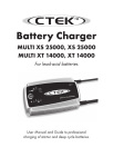
CONGRATULATIONS
to the purchase of your new professional switch mode battery charger. This charger is
included in a series of professional chargers from CTEK SWEDEN AB and represents the
latest technology in battery charging.
SAFETY
•The charger is designed for charging only batteries according to the technical specification.
Do not use the charger for any other purpose.
Always follow battery manufacturers' user and
safety recommendations.
•Never try to charge non-rechargeable batteries.
•Never place the charger on top of the battery
or cover the charger when charging.
•Never charge a frozen or damaged battery.
•Never charge a Li-battery with temperature
below 0°C (32°F) if not specified by the battery
manufacturer.
•Never use a charger with damaged cables.
Ensure that the cables have not been damaged
by hot surfaces, sharp edges or in any other
way.
•Never place a fan-cooled charger so that dust,
dirt or similar can be sucked into the fan.
•A damaged cable must be replaced by a
CTEK representative using an original part
supplied by CTEK. A detachable cable can be
replaced by the user using an original part supplied by CTEK.
•Connection to the mains supply must be in
accordance with the national regulations for
electrical installations.
•Chargers with grounded mains plug must only
be connected to a grounded socket outlet.
•During charging, Lead-Acid batteries could
emit explosive gases. Prevent sparks close to
the battery. Provide for good ventilation.
•Chargers with IP-class lower than IPx4 are
designed for indoor use. See technical specification. Do not expose to rain or snow.
•Connect the charger to the battery´s positive
pole and then to the negative pole. For batteries mounted inside a vehicle, connect the negaEN • 3
EN
MANUAL
tive connection to the vehicle chassis remote
from the fuel pipe. Then connect the charger to
mains supply.
•Disconnect the charger from the mains supply.
Next remove the negative connection (vehicle
chassis) and then the positive connection.
•Don’t leave any battery unattended for a
longer period of time during charging. If any
error occurs disconnect the charger manually.
•(IEC 7.12 ed.5) This appliance is not
intended for use by persons (including children)
with reduced physical, sensory or mental capabilities, or lack of experience and knowledge,
unless they have been given supervision or
instruction concerning use of the appliance by
a person responsible for their safety. Children
should be supervised to ensure that they do not
play with the appliance.
(EN 7.12) This appliance can be used by
children aged from 8 years and above and
persons with reduced physical, sensory or
mental capabilities, or lack of experience and
knowledge if they have been given supervi4 • EN
sion or instruction concerning use of the appliance in a safe way and understand the hazards
involved. Children shall not play with the appliance. Cleaning and user maintenance shall not
be made by children without supervision.
HOW TO CHARGE
1.Connect the charger to the battery.
EN
2.Connect the charger to the wall socket. The power lamp will indicate that the mains
cable is connected to the wall socket. The error lamp will indicate if the battery clamps
are incorrectly connected. The reverse polarity protection will ensure that the battery
or charger will not be damaged.
3.Press the MODE-button to select charging program. 4.Follow the 8-step display through the charging process.
The battery is ready to start the engine when STEP 4 is lit.
The battery is fully charged when STEP 7 is lit.
5.Stop charging at any time by disconnecting the mains cable from the wall socket.
ready to use
fully charged
ERROR LAMP
MODEBUTTON
POWER
LAMP
TEMPERATURE
SENSOR
INDICATOR
NORMAL
BATTERY
PROGRAM
AGM
BATTERY
PROGRAM
RECOND
PROGRAM
SUPPLY
PROGRAM
EN • 5
CONNECT THE CHARGER TO A BATTERY
INFO
If the battery clamps are incorrectly
connected, the reverse polarity
protection will ensure that the battery
and charger are not damaged.
Comfort
Connect
–
+
–
+
For batteries mounted inside a
vehicle
1. C
onnect the red clamp to the battery's
positive pole.
2. Connect the black clamp to the vehicle
chassis remote from the fuel pipe and
the battery.
3. Connect the charger to the wall socket.
4. D isconnect the charger from the wall
socket before disconnecting the battery.
5. D isconnect the black clamp before the
red clamp.
CHARGING programs
Settings are made by pressing the MODE-button. After about two seconds the charger
activates the selected program. The selected program will be restarted next time the
charger is connected.
The table explains the different Charging Programs:
Program
AGM
RECOND
Battery
Size (Ah)
Explanation
20–300Ah
Normal battery program
14.4V/10A. Use for WET batteries, Ca/Ca, MF and for most GEL batteries
-20°C–+50°C
(-4ºF–122ºF)
20–300Ah
AGM battery program 14.7V/10A
Use for AGM batteries.
-20°C–+50°C
(-4ºF–122ºF)
-20°C–+50°C
(-4ºF–122ºF)
20–300Ah
Recond program 15.8V/1.5A
Use to return energy to the empty
WET and Ca/Ca batteries. Recond
your battery once per year and after
deep dischare to maximise lifetime and
capacity. The Recond program adds
STEP 6 to the normal battery program.
-20°C–+50°C
(-4ºF–122ºF)
20–300Ah
Supply program 13.6V/10A
Use as 12V power supply or use for
float maintenance charging when 100%
capacity of the battery is required.
Supply program activates step 7 without
time or voltage limitation.
WARNING!
The spark protection on the battery charger
is disabled during SUPPLY program.
Comfort
Connect
6 • EN
Temp range
ERROR LAMP
TECHNICAL SPECIFICATIONS
1. Is the chargers positive lead connected to the batterys
positive pole?
2. Is the charger connected to a 12V battery?
3. Has charging been interrupted in STEP 1, 2 or 5?
Restart the charger by pressing the MODE-button. If charging is still
being interrupted, the battery...
step 1: ...is seriosly sulphated and may need to be replaced.
step 2: ...can not accept charge and may need to be replaced.
step 5: ...can not keep charge and may need to be replaced.
POWER LAMP
If the power lamp is lit with a:
1. STEADY LIGHT:
The mains cable is connected to the wall socket.
2. FLASHING LIGHT:
The charger has entered the energy save mode. This happens if the
charger isn´t connected to the battery in 2 minutes.
TEMPERATURE SENSOR
The charger is equipped with a temperature sensor. The temperature sensor
will adjust the voltage to the ambient temperature. For MXS 10 EC - the
temperature sensor is not detachable. Activated temperature sensor will be
indicated by a lit temperature sensor indicator lamp.
Model number
1046
Rated Voltage AC
Charging voltage
220–240VAC, 50–60Hz
Start voltage
2.0V
Charging current
10A max
14.4V, AGM 14.7V, RECOND 15.8V, SUPPLY 13.6V
Current, mains
1.4A rms (at full charging current)
Back current drain*
Less than 1Ah/month
Ripple**
Less than 4%
Ambient
temperature
-20°C to +50°C, output power is reduced
automatically at high temperatures
Charger type
8-step, fully automatic charging cycle
Battery types
All types of 12V lead-acid batteries (WET, MF, Ca/Ca, AGM and GEL)
Battery capacity
20–300Ah
Insulation class
IP65
EN
If the error lamp is lit, check the following:
*) Back current drain is the current that drains the battery if the charger is not connected
to the mains. CTEK chargers has a very low back current.
**) The quality of the charging voltage and charging current is very important. A high
current ripple heats up the battery which has an aging effect on the positive electrode.
High voltage ripple could harm other equipment that is connected to the battery. CTEK
battery chargers produce very clean voltage and current with low ripple.
READY TO USE
The table shows the estimated time for empty battery to 80% charge
BATTERY SIZE (Ah)
20Ah
50Ah
100Ah
200Ah
TIME TO 80% CHARGED
2h
5h
10h
20h
EN • 7
CHARGING PROGRAM
SOFT START
BULK
ABSORPTION
ANALYSE
RECOND
FLOAT
PULSE
11
2
3
4
5
6
7
8
AGM
RECOND
15.8V
10A until 12.6V
15.8V
10A until 12.6V
15.8V
10A until 12.6V
Increasing voltage
to 14.4V @ 25°C
10A
Increasing voltage
to 14.7V @ 25°C
10A
Increasing voltage
to 14.4V @ 25°C
10A
14.4V @ 25°C
Declining current
Checks if voltage
drops to 12V
13.6V
10A
12.7V‒14.4V
10‒2A
14.7V @ 25°C
Declining current
Checks if voltage
drops to 12V
13.6V
10A
12.7V‒14.7V
10‒2A
14.4V @ 25°C
Declining current
Checks if voltage
drops to 12V
13.6V
10A
12.7V‒14.4V
10‒2A
Max 15.8V
1.5A
Max 13.6V
10A
SUPPLY
Limit:
Max 8h
Max 8h
Max 20h
Max 10h
STEP 1 desulphation
Detects sulphated batteries. Pulsing current and voltage, removes sulphate from the lead
plates of the battery restoring the battery capacity.
STEP 2 soft start
Tests if the battery can accept charge. This step prevents that charging proceeds with a
defect battery.
STEP 3 bulk
Charging with maximum current until approximately 80% battery capacity.
STEP 4 absorption
Charging with declining current to maximize up to 100% battery capacity.
8 • EN
3 minutes
30 min or 4h
depending on
battery voltage
10 days
Charge cycle restarts
if voltage drops*
Charge cycle restarts
if voltage drops
*Supply program is not time or voltage limited.
CURRENT (A)
VOLTAGE (V)
DESULPHATION
STEP 5 analysE
Tests if the battery can hold charge. Batteries that can not hold charge may need to be replaced.
STEP 6 recond
Choose the Recond program to add the Recond step to the charging process. During the Recond step
voltage increases to create controlled gasing in the battery. Gasing mixes the battery acid and gives
back energy to the battery.
STEP 7 float
Maintaining the battery voltage at maximum level by providing a constant voltage charge.
STEP 8 pulse
Maintaining the battery at 95–100% capacity. The charger monitors the battery voltage and gives a
pulse when necessary to keep the battery fully charged.
LIMITED WARRANTY
EN
CTEK SWEDEN AB, issues this limited warranty to the original purchaser of this product.
This limited warranty is not transferable. The warranty applies to manufacturing faults
and material defects for 2 years from the date of purchase. The customer must return the
product together with the receipt of purchase to the point of purchase. This warranty is void
if the battery charger has been opened, handled carelessly or repaired by anyone other
than CTEK SWEDEN AB or its authorised representatives. One of the screw holes in the
bottom of the charger is sealed. Removing or damaging the seal will void the warranty.
CTEK SWEDEN AB makes no warranty other than this limited warranty and is not liable
for any other costs other than those mentioned above, i.e. no consequential damages.
Moreover, CTEK SWEDEN AB is not obligated to any other warranty other than this
warranty.
SUPPORT
Fore support and more information about CTEK products: www.ctek.com, [email protected],
[email protected], +46(0) 225 351 80. For latest revised manual see www.ctek.com.
EN • 9
10 • EN
20014905G