1
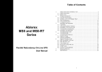
P15571
Rev 2
Test Plan
This document will detail the team’s plan to test that the engineering requirements of the project are
met. Some of the items found in this report are on-going, so this report will be updated periodically.
Table Contents
Mechanical Testing ....................................................................................................................................... 3
ER1: “Rotate dish azimuth” Minimum 210°.............................................................................................. 3
ER2: “Change dish altitude” Minimum 20-72°.......................................................................................... 3
ER4: “Track sun’s daily path” .................................................................................................................... 3
ER5-6-7: “Environmental Resistance” Minimum IP54 .............................................................................. 3
ER8: “Wind Resistance” Maximum operating wind speed of 49 MPH ..................................................... 5
ER14: “Limit Declination” Prevent over-extension and over-retraction .................................................. 5
ER14: “Limit Rotation” Prevent over-rotation of the slewing drive (<360°)............................................. 5
ER24: “Rotate Azimuth” Minimum 150 ft.lb of torque............................................................................. 6
ER25: “Rotate Azimuth” Resist wind over-turning moment .................................................................... 6
ER26: “Rotate Azimuth” Support Iced dish weight ................................................................................... 6
ER29: “Move declination” Provide sufficient force to move the dish ...................................................... 7
ER31: “Resist Backlash” resist backlash from reversed loading ............................................................... 7
ER31: “Resist Backlash” resist backlash from reversed loading ............................................................... 7
Electrical Testing ........................................................................................................................................... 7
ER8: “Protects Electrical Systems” Short Circuit Protection ..................................................................... 7
ER9: “Protects Electrical Systems” Open Circuit Protection ..................................................................... 7
ER11: “Protects DAQ” Runs on Backup Power for 2 Minutes................................................................... 7
ER17: “Collect Data” Movement of Dish does not Affect Collected Data ................................................ 8
ER27: “Rotate Azimuth” Motor Shield can Support Power Requirements of Slewing Drive ................... 8
ER28: “Move Declination” Motor Shield can Support Power Requirements of Linear Actuator ............. 8
ER32: “Feedback of Position” Controller Reads Feedback from Encoders Properly ................................ 8
ER33: “Protects Electrical Systems” Electrical Systems Must Be Able to Survive Hard Reset .................. 8
ER34: “Movement” Controller Must be Able to See a Specific Resolution from Motor Encoders .......... 9
Software Testing ........................................................................................................................................... 9
Other Testing ................................................................................................................................................ 9
ER18: “Documentation” User’s Manual is Provided ................................................................................. 9
P15571
Test Plan
Rev 2
P15571
Rev 2
Test Plan
Mechanical Testing
ER1: “Rotate dish azimuth” Minimum 210°
ER1 will be tested once the Slewing drive has been received by the team. The slewing drive is
designed for continuous rotation, but this will be verified by running the motor at an
appropriate duty cycle to ensure the drive works properly. Assuming a 50% duty cycle, the 360°
rotation test should take about 1 hour.
ER2: “Change dish altitude” Minimum 20-72°
ER2 can only be tested when the LA is installed in the actual dish system. Preliminary fit checks
and range of motion checks have been completed in CAD, and have shown the LA should
produce an angle range of 15-75°. This will surpass the requirement of 20-72° if everything is
installed correctly.
The team has both a dial inclinometer and smart phone apps that can verify whether the dish is
achieving the expected range of motion. Once the LA is installed, it will be fully retracted and
fully extended. The angles produced at each extreme will be measured to verify the true range
of motion.
ER4: “Track sun’s daily path”
CAD simulation work has shown that the tracking algorithms and drivers should produce the
desired tracking accuracy. The motors are speeds are also more than sufficient to meet the
rotational/inclination speed requirements.
Once the LA and slewing drive are installed, testing of the systems accuracy can begin. The beam
width of the antenna is estimated to be 2° and the sun has an angular size of 0.5°. Updating
roughly every 6 minutes, the dish system can keep the sun inside the beam. Simply adjusting
some accuracy parameters in the RadioEyes telescope file, this time can be shortened to make
the dish update more frequently if needed.
To fully test the system once it is functional, the system will be left to operate for a number of
days. The collected data will be analyzed to ensure the data is continuous, and the suns
signature has not been lost (or is intermittent). If there are any problems with the data, such as
the data being spotty, or not appearing at all, the team will know that the dish has been
calibrated inaccurately and a re-calibration will be done.
Testing for a number of days will also allow the team to test whether or not the dish software
follows all appropriate set-up steps, shut-down steps, and data saving steps. The dish system
should also shut off the receiver once the sun has set below the tree line, so this can be verified
as well.
ER5-6-7: “Environmental Resistance” Minimum IP54
Since the dish will be autonomous and operate outdoors, the system must be robust enough to
resist all environmental conditions (with the exception of 50+ Mph winds, to be discussed later).
P15571
Rev 2
Test Plan
IP ratings will be discussed in this section. An IP chart can be found below for reference.
[http://www.juiceelectricalsupplies.co.uk/wordpress/wp-content/uploads/2013/04/iptable.jpg]
The dish system as a whole should meet a IP rating of 54 at a minimum, which means the dish is
resistance to dust and particle ingress (intrusion of small amounts of dust does not hinder
operation) and protected against low pressure water jets (similar to a stream from a hose, or a
heavy rain). Components purchased and planned for purchase thus far have been chosen to
meet this standard individually so no additional waterproofing must be done. The linear
actuator is rated for outdoor use, with an IP 65 rating. The slewing drive and its motor are both
rated IP54 when installed in the correct orientation. All wires will lead to a weatherproof
enclosure to be purchased by the customer. The cables will enter the box via a cable gland to
prevent moisture/water/dust ingress from outside. The LA and Slewing Drive (SD) can be tester
for their environmental resistance by spraying them with a rose for a couple minutes, then
confirming operating of the devices is not affected.
There is a planned accelerometer to provide feedback to the driver and alert it if there is an
elevation that does not match the expected value. This accelerometer will be on the dish’s
declination bracket, and must be waterproofed in some way. A small plastic waterproof box will
be purchased to protect the accel and allow the cable to leave (again through a cable gland).
This box’s water resistance will be tested in a similar fashion to the LA and SD.
Ingress of dust will not pose a serious issue for any components, and will not be tested
specifically. In general, a waterproofed enclosure or device is protected from dust by its very
nature. Any components that can meet the IP#4 requirements will be sufficiently protected for
our application. There is also not a high likely hood of a dusty environment where the dish will
operate.
IP54 will also provide sufficient protection against snow, even though it is not stated in the IP
chart.
P15571
Rev 2
Test Plan
Besides ingress or water and dust, other environmental concern is temperature. The LA and SD
motors are rated to operate at -20F. Since the dish will partially be constructed in the winter,
there will likely be a few opportunities to test the motors at very low temperatures. If the
weather does not permit the testing, the team will seek out a sub-zero cooling unit that can
support the motor testing. The motors should operate at the specified -20F temperature, and
ideally will operate at even lower temperatures.
ER8: “Wind Resistance” Maximum operating wind speed of 49 MPH
As part of feasibility, wind loading on the dish was investigated. Based on the finding it was
decided that the dish should not operate in winds of 50MPH or greater, both due to loading on
the system and the effect on the systems accuracy. The team plans to tap into the Farash
center’s wind speed meter, and receive wind speed updates. When the wind approaches 50
MPH the dish will send a text or email warning to the customer (or whoever is specified) to alert
them that the dish will be shutting down.
This system will be tested by passing a dummy wind speed reading of 50+ MPH to the system,
and seeing how the system responds. The team will verify the dish send the warning, and then
shuts down the system correctly. Shut-down should include stopping data collection, uploading
the last data packet to eCallisto, retracting the LA to point the dish upward, and then pausing
the RadioEyes program. The system should come back online after a specified time has passed
with winds less than a threshold value.
ER14: “Limit Declination” Prevent over-extension and over-retraction
ER14 is concerned with keeping the declination of the dish (the LA’s extension) within safe
limits. The first line of defense to prevent over extension/retraction will be the software driver.
The driver will not command the LA to retract or extend past certain values (customizable to
allow for a different LA to be used in the future). The driver already has this protection built it,
and it has been tested in conjunction with the CAD model. The driver safely prevented the dish
from over-extending past the programmed 15°. When the LA arrives, testing will begin to ensure
that the encoder precision and other attributes are correct. Low duty-cycle testing can then be
done to test that the driver extends and retracts the LA to the limit points repeatedly without
issues.
In the event that the software has the wrong encoder count, or something else goes wrong, the
LA has internal limit switches to prevent damage to the device. The functionality of these will be
tested by running the LA to these ‘hard stops’.
In the event that there is a collision at or before the fully extended limit due to some unknown
occurrence, a shear pin is being designed to allow the LA to safely detach itself from the dish.
The team hopes to fabricate some shear pins and test their strength with one of the ME tensile
testers. Before this can happen though, the final pin design needs to be looked at by a SME.
ER14: “Limit Rotation” Prevent over-rotation of the slewing drive (<360°)
The slewing drive has the potential to rotate past 360°, but since the top of the dish assembly
has cables coming from it we don’t want them to become strained or torn out. Again, the first
P15571
Rev 2
Test Plan
line of defense against this is the software limits. As long as the system knows where it is, the
software should be able to prevent over-rotation.
Software limits will be tested by running the drive at a low duty cycle to and from the software
limits. The drive will operate for a long duration to ensure that the encoder accuracy is also
being maintained. At the end of the test, the final position of the drive should be a set known
value. The team will measure the rotation to verify the drive is resting in the final position.
If the software fails, or the positional information is wrong, the team wants to implement a limit
switch on the slewing drive. The design of this feature is still in the brainstorming stages because
the drawings and 3D CAD model for the drive do not provide sufficient information. The current
plan is to either affix a limit switch inside the inner drum of the SD where one wall rotates next
to another, or to put a switch on the wiring, that shuts power off if the wires are over-tensioned.
Both of these limit switch ideas can be tested easily in the lab when the team gets the drive. Lab
testing will also verify whether or not the limit switch wiring is done correctly.
ER24: “Rotate Azimuth” Minimum 150 ft.lb of torque
The selected slewing drive provides more than 300 ft.lb of torque, which the drive rated to
withstand over 2800 ft.lb of torque. The team can test the torque of the SD by mounting it on its
side and attaching an arm linkage to the opposite face. Weight can be applied to the end of the
arm until a moment of 150 ft.lb or more is applied. The SD should be able to rotate the mass
with little trouble. This test may not be feasible without help from the ME machine shop staff,
who may not be able to help set up the test. A location or plate to mount the drive to may also
not be available. The team will have to discuss if this testing is truly necessary since the drive will
far exceed even the worst case loading requirements.
ER25: “Rotate Azimuth” Resist wind over-turning moment
The drive is rated to withstand 5,700 ft.lb. The calculated wind loads at 50 MPH will not exceed
1000 ft. lb. There is no current plan to test this requirement due to the strength of the drive. To
achieve 1000 ft.lb of torque on the drive face would also be difficult and resource intensive for
the team.
Though there is not plan to test this requirement, one possibility would be to it is possible that a
tensile tester could be used to apply a load at the end of an arm attached to the SD. The SD
mounting face would have to be bolted to a plate and clamped in place. A skid plate would also
have to be used to allow the SD to rotate the arm underneath the tensile tester piston. The
piston would ride on top of the plate, applying its load continually. The resources to do this test
would likely not be available for free. The team would have to invest some of the budget into
manufacturing and purchasing materials for the plate and arm.
ER26: “Rotate Azimuth” Support Iced dish weight
The SD is rated for multi-thousand pound loading in the axial direction, and the iced dish is
estimate to weigh no more than 250 lb. To verify slewing drive operation under roughly 250lb
loading, two P15571 team members can stand on the drive while the motor is running.
P15571
Rev 2
Test Plan
ER29: “Move declination” Provide sufficient force to move the dish
The LA must provide enough force to overcome the force of an iced dish under high winds (49
MPH). The LA’s strength can be tested by mounting it in a vice (with the back pin) vertically and
adding weights to the LA piston pin. The LA needs to provide roughly 300 lb maximum, but is
rated for 400 lb. Testing the LA under increasing loads will also allow the team to characterize
the motor and understand the current draw as a function of load.
ER31: “Resist Backlash” resist backlash from reversed loading
The SD is driven by a hour-glass worm gear and is rated for not more than 0.2° of backlash. The
team will test this by running the drive in one direction, stopping the drive, and then accurate
measuring the angular position from a reference point (i.e. the edge of a fixed nearby object to
the center of a bolt hole). The drive will then be torqued in both directions with an arm attached
to the head of the drive. The reference dimension can be re-measured to see if any substantial
backlash has occurred.
Alternatively, the team can print a paper ring with degrees marked on it and tape it to the drive
to measure deflection.
ER31: “Resist Backlash” resist backlash from reversed loading
The LA is driven by a ACME or ball screw, and will resist backlash by design. The LA can be
mounted in a similar manner to the test of ER29, except with the LA pointing up. The LA will be
extended, and then measured. A heavy load can then be applied to the piston pin, and the LA
extension can be re-measured to see if any compression has occurred.
Electrical Testing
ER8: “Protects Electrical Systems” Short Circuit Protection
Short circuits can originate from many sources, including contact foreign conductive materials,
exposed wiring, and unintended electrical connections. Our protection against exposed wiring
and unintended electrical connections are secure and clean wiring/components as well as
component covers where appropriate. There is no good way to test our protection without
damaging our system, therefore all installation must be done with the upmost scrutiny.
ER9: “Protects Electrical Systems” Open Circuit Protection
To protect against open circuits, the system will be installed with care. To test if the connections
are correct, they can be tested using a multimeter.
ER11: “Protects DAQ” Runs on Backup Power for 2 Minutes
The UPS can be tested by starting with only the PC connected to the AC power (via the UPS) and
then disconnecting it. The UPS should alert the PowerChute software in the PC. The PowerChute
software should then run the necessary commands to prepare our system for hibernation. Then
it should enter hibernation. Then when Team Viewer is used to access the PC, it should wake
from hibernation and allow the user to save the OVS from the run before power loss in order to
pass.
P15571
Rev 2
Test Plan
ER17: “Collect Data” Movement of Dish does not Affect Collected Data
The motor noise emitted during operation will be compared against the RF data collected during
normal operation. If the motor noise is not significant according to the User’s approval than the
RF data collection will not be stopped when the motors are operating. If the User determines
that the RF noise is significant, then the RF data collection will need to be stopped while the
system is moving. The system passes if the User is satisfied with the collected RF data.
ER27: “Rotate Azimuth” Motor Shield can Support Power Requirements of Slewing
Drive
The driving capabilities of the Motor Shield will be tested with three scenarios. First, the Slewing
Drive will be ran at varying duty cycles with only the itself connected to the shield. The duty
cycles TBD, but based off the maximum duty cycle needed in normal operation. Successful
operation is determined by the ability of the motor to meet our movement requirements
without drawing the total amount of current provided by the PS. The other two scenarios will be
tested in the same way but the second scenario has the Linear Actuator motor attached as well
but not operating. The third scenario will attempt to move both the Slewing Drive and Linear
Actuator at the same time at a low duty cycle. This is not an actual operation scenario but will
help test the capabilities of the motor shield and its power supply. To pass, the Motor Shield
must allow the Slewing Drive to operate in both the first and second scenario without being
current limited.
ER28: “Move Declination” Motor Shield can Support Power Requirements of
Linear Actuator
See ER27, the Linear Actuator will be tested in the same way but at the following TDB duty
cycles.
ER32: “Feedback of Position” Controller Reads Feedback from Encoders Properly
The Arduino and Hardware Counter will be fed signals representing encoder inputs but at
frequencies higher than will be encountered when attached to Encoder. This will ensure the
system can handle the Encoder signals. The Encoders will then be attached and ran to make sure
all pulses are captured. If the first test with the signal generators are correct but the Encoders
do not function when connected, the failure will be at the Encoder connection. The frequency
the signal generators will run at will be 50 kHz, but the expected Encoder pulse frequencies will
be less than 100 Hz. The system must work at the 100 Hz rate at a minimum to pass.
ER33: “Protects Electrical Systems” Electrical Systems Must Be Able to Survive
Hard Reset
The controller will be turned off when simulating operation (without motors attached) and then
turned on according to the PC initialization routine. It should attempt to move the system to a
known location. If it behaves as expected, the motors will be attached and the same test will be
ran. If the controller moves the motors to the expected extensions/rotations then it will be
considered successful.
P15571
Rev 2
Test Plan
ER34: “Movement” Controller Must be Able to See a Specific Resolution from
Motor Encoders
First the maximum encoder pulses will be determined empirically. The LA and Slewing Drive will
be set to move at a specific frequency. Then the time to run from full extension/retraction to full
retraction/extension will be determined (or 360 revolution for the Slewing Drive). This
information gives the total pulse count of the LA and Slewing Drive. Then the LA and Slewing
Drive will run again from limit to limit, the controller and Hardware Counter must be able to
count all pulses. If the Controller/Hardware Counter reports a pulse count within 0-TBD pulses,
then it passes.
Software Testing
Other Testing
ER18: “Documentation” User’s Manual is Provided
The compiled User’s Manual will be provided as soon as a draft is completed for the User to
review. As soon as the prototype is complete, the User will be asked to perform tasks according
to the User manual. If there are no objections from the User and all operations can be
performed according to the manual, it will be considered tested.
Control Loop Methodology Testing
We will compare a closed loop system and an open loop system where the pwm for the open
loop system is replicated from the pwm of the closed loop system. The reason for wanting an
open loop system with variable pwm is two part. First, having an open loop system allows the
driver to continue interacting with the micro-controller which allows us to do things like abort
slews and poll the current location of the dish. Secondly, the variable pwm will help to reduce
the stopping forces of the motors. The reason for testing is to compare the run time and error
(how many time each method has to reverse direction) of each method and see if the open loop
is acceptable and comparable to the closed loop system which should be quicker.
The test method will be as such:
●
●
●
Define 100 positions on the linear actuator that meet the following characteristics
○
25 positions within 25% max distance of the previous For example, if the first
point is 0inch, then the second point must be in range (0,3 inches). Let the
second point be 1.5 inches. Then the third point must be in the range (0,4.5
inches)
○
25 positions within 50% max distance of the previous
○
25 within 75% of max distance of previous
○
25 points where the difference is 1 degree altitude (this requires knowing
precision of linear actuator)
Using closed loop control system, run through each set of points documenting runtime
and number of reverses.
Using open loop control system, run through each set of points documenting runtime
and number of reverses.
P15571
Rev 2
Test Plan
●
Compare performance.
○
For errors, the better performing method will have fewer errors.
○
For timing, the two systems can be considered comparable if
■
the average time per tick are within X% (need discussion on
comparability).
■
Overall time is within Y%