1
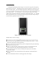
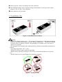
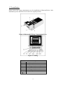
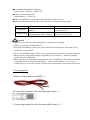
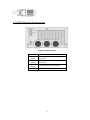
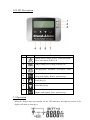
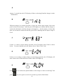
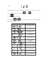
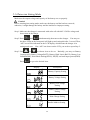
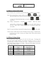
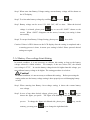
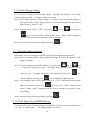
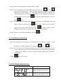
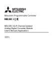
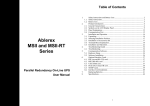
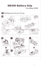
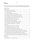
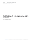
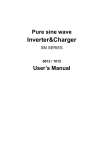
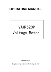
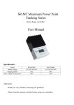
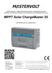
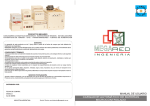
Photovoltaic Charger PCM4048/PCM6048 12/24/36/48 Vdc User’s Manual Content IMPORTANT NOTES .............................................................................................................. 3 1.0 INTRODUCTION ........................................................................................................... 4 1.1 INSTALLATION SITE .................................................................................................... 5 1.2 INSTALLATION ............................................................................................................ 6 1.3 ACCESSORIES.............................................................................................................. 7 1.4 LED INDICATION EXPLANATIONS .............................................................................. 8 2.0 LCD DESCRIPTION ..................................................................................................... 9 2.1 OPERATION ................................................................................................................. 9 2.1.1Enter into Setting Mode ....................................................................................................................... 12 2.1.2Battery Capacity(AH) Setting .............................................................................................................. 13 2.1.3Battery Voltage Setting ........................................................................................................................ 13 2.1.4 Battery Over-voltage Limit Setting ..................................................................................................... 14 2.1.5 Battery Under-Voltage Limit Setting .................................................................................................. 15 2.1.6 Pulse Charge Setting ........................................................................................................................... 16 2.1.7 Parallel Address Setting ...................................................................................................................... 16 2.1.8 Total Input Power(KWH)Setting: ....................................................................................................... 16 2.1.9 Parameters Displayed .......................................................................................................................... 17 2.2 LCD DISPLAY EXPLANATIONS ................................................................................. 17 2.3 ERROR CODES .......................................................................................................... 19 3.0 PRODUCT SPECIFICATIONS........................................................................................ 20 2 Important Notes 1. Keep this user’s manual and follow all instructions indicated in the manual. 2. Don’t overload the charger. 3. Don’t split the charger apart; otherwise, your warranty is void. 4. Only authorized technician may repair or replace the interior components. 5. Make sure the ground of the load is connected properly. Otherwise, you may get electrical shock. 6. Keep the PV charger clean and dry. 7. Make sure all the contacts with correct polarity to avoid from short circuit. 8. Following the instruction of the user’s manual to use or configure the charger. 3 1.0 Introduction PCM4048/PCM6048 photovoltaic charger is to convert the energy from solar panel to load or batteries connected. With different load or batteries connected, it can be set as 12V, 24V, 36V or 48V system. The solar charger can get max. efficiency up to 95%. The solar cells can get the highest efficiency by means of Maximum Power Point Tracking(MPPT) and pulse charge method.. Via LCD display, it is easy to get input voltage/current, output voltage, battery temperature(with battery temperature compensation feature)…etc.. Through RS232 communication port, our monitoring software may provide output voltage setting or record all relative parameters from the PV charger. Figure 1: The front view of the PV charger Standard features of the PV Charger: Maximum Power Point Tracking(MPPT) maximizes energy harvest from the PV array. Auto-selection Four-stage (Bulk/Pulse/Float1/Float2) charge mode to reduce 1~3 times charge time and maximize system performance. Easy-to-read LCD and four functional key pads for configuration and system monitoring. Maximum efficiency up to 95%. Input over-voltage and under-voltage protection, output over-current protection and back-feed protection with warning messages appeared on LCD and LED. Over-temperature protection and power derating when output power and ambient temperature are high. Battery temperature sensor automatically provides temperature compensated battery charging. Provide communication software to monitor the status of the charger. 4 Smart fan speed Control according to the load connected. This intelligent charger may set output voltage automatically or user may select output voltage 12/ 24 /36/ 48 V via LCD panel。 Allow multi devices in parallel. 1.1 Installation Site Figure 2: Installation Environment Notice! 1.Inspect the charger upon receipt. This product is designed to be with robust packaging. However, accidents and damage may occur during transportation. Notify the forwarder or dealer if there is damage occurred. The packaging is recyclable; save it for reuse or dispose of it properly. 2.It is designed to be installed and commissioned in a sheltered controlled environment as follows: --Operating temperature -20°C ~60°C. --Always avoid from contact with direct sunlight. --Install it away from objects that give off excessive heat and areas that are excessively wet. . --Install it indoors as it is not designed for installation outdoors. Figure 3: Installation Site 5 1.2 Installation Please remove the wiring compartment cover for installation as illustrated below. After installation, please fasten the cover back to its original position. Figure 4: Disassemble Wiring Compartment Cover Figure 5: Cabling PV+ PVBat+ BatLoad+ LoadBTS Contact Description To the positive(+) of solar cell To negative(-) of solar cell To the positive(+) of Bat. input To the negative(-) of Bat. input To the positive(+) of Load To the negative(-) of Load Battery Temperature Sensor Ground 6 ■Recommended Installation Sequence: Connect Load → Battery → Solar Cell ■If there is no load connected Connect Battery → Solar Cell ■Make sure the BTS wire is installed and fixed to the contact (CN11). ■Make sure the Battery and load are removed before entering into setting mode. Mode Load Mode Charging Mode Description Output without connecting with battery. Output connecting battery or connecting both battery and load. Remarks Output voltage via LCD panel is required to be set.. Output voltage via LCD panel can be fixed or auto set. Caution! 1. Make sure all cables are connected properly without short-circuiting. 2. There is 100A fuse inside the (BAT+). 3. Disconnect the Battery if there is no solar cell and load connected or if the solar cell is sheltered for a long while. 4. Do not overload the charger! Please refer to specification sheet to use the charger properly. 5. Make sure the voltage and capacity of the Battery is set correctly. Re battery setting, please refer to 2.1 Operation 6. Make sure the bat. Temperature compensation wire is installed and fixed where the battery is installed, not in the internal of the battery. Make sure the adhesive use is easy to conduct heat, so as to make sure the accuracy of the temperature compensation of the unit. 1.3 Accessories 1.Battery Compensation wire(BST) × 1 2.Connecting terminal to the solar panel(phi4-male) × 1 3.Connecting terminal to the solar panel(phi4-female) × 1 7 1.4 LED Indication Explanations Figure 6: Bottom View LED Fault (Red) PV Low (Amber) Normal (Green) RS232 Description System Fault, Protection Circuit is activated. Under-voltage/Over-voltage of Solar Cell System Operation in Normal RS232 Communication Interface 8 2.0 LCD Description Item Symbol Description 1 System Fault, Charger goes to “Protection Mode” Error code shown on the LCD 2 Under-voltage/Over-voltage of Solar Cell 3 Charging Mode –Illuminate / Load Mode - Flash 4 Function Key (Left: push slightly; Return: push heavily) 5 Scroll Key-Up 6 Scroll Key-Down 7 Function Key (Right: push slightly; Enter: push heavily) 2.1 Operation When the charger starts up normally, all the LED indicators will light up and the LCD display will show as drawing A. 9 A Approx. 3 seconds later, the LCD display will show as drawing B and the charger is under initialization. B When the charger is in normal operation, it shows the current input voltage of the solar panel as shown in drawing C, then the green LED lights up to indicate that the charger is connected with batteries and also charges to the batteries. On the contrary, it shows that there are no batteries connected when the green LED is blinking and the output voltage is fixed. C If there is a defect occurred during operation, the LCD display shows Er04 as shown below. For more detailed error code, please refer to Table 1 Error Code. D If there is over-voltage or under-voltage occurred during operation, the LCD display will show Alarm code as indicated below and the Amber LED lights up. E Press press key to indicate the parallel address of the charger as shown as drawing F and key once again or wait for 10 seconds to go back to Main Menu. 10 F After turning on the PV charger, it will display current solar cells’ voltage. like to see other parameters, you may press Caution: You may press key or If you would key. keys are of no use. or key to scroll up and down to get different display information and message. Display Description Input Voltage of Solar Panel Input Current of Solar Panel Input Power of Solar Panel Total input Power of Solar Cells Battery Voltage Current supplied to batteries Current battery capacity set Battery Temperature(℃) IGBT Temperature(℃) Battery Temperature(℉) IGBT Temperature(℉) 11 2.1.1Enter into Setting Mode Make sure the output voltage and capacity of the battery are set properly. Caution! Before entering into setting mode, make sure the battery and the load are removed; otherwise, it might damage the battery and the load due to improper setting. Step1: Make sure the charger is connected with solar cell with 40V~150Vdc voltage and do not turn on the charge. Step2: Press and simultaneously, then turn on the charger. You may see the three LEDs on the front panel will light up and extinguish after 3 second. Then, “AH” text will be indicated on the LCD display, which means the charger is in setting mode now. If no “AH” text shown on the LCD, you need to repeat Step 2. Step3: Press or to choose item to be set. Basically, you may set Battery Capacity(AH), Battery Voltage(BATT), Battery High Limit (BAUP), Battery Low Limit(BADW), Pulse Mode Setting(PULS), ID(ID), and total input power(KWH). Press to go to the desired item. Display Description Battery Capacity Setting Battery Voltage Setting Battery Over-voltage Setting Battery Under-voltage Setting Pulse Charge Setting Parallel Address Setting 12 Total Input Power(KWH) Setting 2.1.2Battery Capacity(AH) Setting Step1: It indicates the current battery capacity when getting into Battery Capacity setting. Step2: Select desired battery capacity (AH) by scroll key or key. The digit with flashing cursor means the desired one to be changed. If you would like to change the left-hand/right-hand digit, you may press respectively. Step3: Battery Capacity(AH) is selectable from 1~999AH. key or key When the desired capacity(AH) is selected, please press key to save till “SAVE” shown on the screen. When “SAVE” disappears on the screen, it means your setting is done successfully. Step4: To escape from Battery Capacity(AH) setting, please press key for a while. Caution: If there is ER39 shown on the LCD display after the setting is completed and a re-starting process is done, it means your setting is failed. Please proceed desired setting once again. 2.1.3Battery Voltage Setting The selectable battery voltage settings are 12V, 24V, 36V, 48V or auto. The charger will check the selected voltage matched to the batteries connected. In case it is out of acceptable range, it will show it as battery out of order. Meanwhile, the user can self set battery under-voltage and battery over-voltage. When the AUTO setting is selected, the voltage window will be as below: Battery Voltage Auto Detecting Voltage Range Self-Setting Voltage Range(default) 48V 44~56V 42~54.6V 36V 33~42V 28~40.9V 24V 22~28V 18~27.3V 12V 11~14V 9~13.6V 13 Step1: When enter into Battery Voltage setting, current battery voltage will be shown on the LCD display. Step2: To select other battery voltage by scrolling key and key. Step3: Battery voltage can be set as 12V, 24V, 36V, 48V or Auto. When the desired voltage is selected, please press key to save till “SAVE” shown on the screen. When “SAVE” disappears on the screen, it means your setting is done successfully. Step4: To escape from Battery Voltage Setting, please press for a while. Caution: If there is ER39 shown on the LCD display after the setting is completed and a re-starting process is done, it means your setting is failed. Please proceed desired setting once again. 2.1.4 Battery Over-voltage Limit Setting In normal condition, it is not necessary to calibrate this setting as long as the battery voltage selected is within window. For example, if the user selects 24V, the default over-voltage is 27.3V. In case the battery voltage desired is higher than this voltage, you may calibrate battery voltage to be higher. The setting procedure is as below: Caution! In normal condition, it is not necessary to calibrate this setting. Before processing the setting, make sure the battery voltage setting is done properly to avoid damaging battery or load. Step1: When entering into Battery Over-voltage setting, it shows the current battery over-voltage. Step2: In case of any other desired voltage, please press key or key to choose the figure you prefer. The figure with blinking means the current place you are. To change the figure at left-hand side, please press contrary, you may press key to change the right-hand side. 14 key, on the Step3: After the battery over-voltage is selected, please press key to save till “SAVE” shown on the screen. When “SAVE” disappears on the screen, it means your setting is done successfully. Step4: If you would like to escape from battery over- and under- voltage setting, please press key to escape. 2.1.5 Battery Under-Voltage Limit Setting In normal condition, it is not necessary to calibrate this setting as long as the battery voltage selected is within window. For example, if the user selects 24V, the default under-voltage is 18V. In case the battery voltage desired is lower than this voltage, you may calibrate battery voltage to be lower. The setting procedure is as below: Caution! In normal condition, it is not necessary to calibrate this setting. Before processing the setting, make sure the battery voltage setting is done properly to avoid damaging battery or load. Step1: When entering into Battery Over-voltage setting, it shows the current battery under-voltage. Step2: In case of any other desired voltage, please press key or key to choose the figure you prefer. The figure with blinking means the current place you are. To change the figure at left-hand side, please press contrary, you may press key, on the key to change the right-hand side. Step3: After the battery under-voltage is selected, please press key till “SAVE” shown on the screen new parameter. If the “SAVE” extinguishes from the screen and show “OVER” instead. It means the voltage selected is higher than the battery’s over-voltage. Step4: If you would like to escape from battery over- and under- voltage setting, please press key to escape. 15 2.1.6 Pulse Charge Setting It is to set if the charger can be in pulse charge. Basically, the charger is set at Pulse Charge setting as default. Setting procedure is as below: Step1: Step1: Enter into Pulse Charge Setting. If it shows “ON” it means the charger is able to be in Pulse Charge; on the contrary, it means the charger is not able to be in Pulse Charge if it shows “OFF”. Step2: You may select “ON” or “OFF” by pressing key or key, then press key to save till “SAVE” shown on the screen. When “SAVE” disappears on the screen, it means your setting is done successfully. Step3: You may escape from this setting by pressing key. 2.1.7 Parallel Address Setting When there are several chargers in parallel, you may proceed the setting as below: Step1: Enter to Parallel Address Setting, then the charger will show the address of the charger in parallel. Step2: To select other desired parallel address, you may press key or key to choose the figure you prefer. The figure with blinking means the current place you are. To change the figure at left-hand side, please press key, on the contrary, you may press key to change the right-hand side. Step3: The selectable range of the parallel address is 1~254. When the desired parallel address is selected, please press key to save till “SAVE” shown on the screen. When “SAVE” disappears on the screen, it means your setting is done successfully. Step4: You may escape from this setting by pressing key 2.1.8 Total Input Power(KWH)Setting: To set the initial value of the total input power(KWH), user may set the total input power to “zero” or “certain value”. The setting method is as below: 16 Step1: Enter into total input power setting, it shows ”0000”。 Step2: If you would like to set other initial value, you may use key or key to select desired value. When the figure selected is blinking, it means the figure that you may change. “K” at the right-hand side means “1000”times, so if the screen shows 123K means 123000 KWH. If you would like to change the left-hand figure, you may press key and the right-hand figure, you may press key. Step3: The range of the total input power can be selected from 0~999K KWH. Once the figure is selected, you may press key to save. Make sure the “SAVE” shown on the screen, then you may release key now. When “SAVE” disappears on the screen, it means your “save” is done successfully. Step4: You may escape from this setting by pressing key 2.1.9 Parameters Displayed Step1: After turning on the PV charger, it will display current solar cells’ voltage. would like to see other parameters, you may press key or If you key. Step2: The LCD can show the following data, such as the voltage of the solar cells, the input voltage/current of the solar cells, the input power of the solar cells, battery voltage/current, Battery Capacity set(AH), charger temperature and battery temperature. Caution: keys are of no use. 2.2 LCD Display Explanations Display Description Input Voltage from Solar Cells Input Current from Solar Cells 17 Input Power from Solar Cells Total Input Power of the solar Cells Battery Voltage Current supplied to Battery Current Battery Capacity Setting Battery Temperature in Celsius IGBT temperature in Celsius Battery Temperature in Fahrenheit IGBT temperature in Fahrenheit Battery Capacity Setting Directory Battery Voltage Setting Directory Battery Over-voltage Setting Battery Under-voltage Setting Pulse Charge Setting Parallel Address Setting Total Input Power(KWH) Setting Battery Capacity configuration 18 Battery Voltage configuration New parameters set are under saving. 2.3 Error Codes When the charger can not work normally, it will show the error code on the LCD display as Table 1. You may proceed troubleshooting indicated as below. Error Code Description Trouble Shooting AL04 Input Over-voltage Reduce input voltage AL05 Input Under-voltage Increase input voltage Battery Voltage different Ensure battery voltage and proceed from Setting setting ER11 Input over power Decrease solar power (Watt) or reduce load connected ER13 Output Short Circuit Check to see if the output short circuit is removed. ER17 EEPROM Error Consult with your local agent ER18 Over-heat Reduce the ambient temperature and reduce load connected. ER25 Input Over-current Decrease solar power(Watt) or reduce load connected. ER28 Output Voltage too high Re-start the charger ER32 Memory Error Re-start the charger ER33 Charger is self-locked Check to see if the operation condition is complied with what the charger requires. ER34 Crystal damage Consult with your local agent ER35 Output voltage too low The charger will be automatically re-start after 15 seconds. ER36 Bat. Over-heat Reduce the environmental temperature of the battery ER37 Fan out of order Check to see if fan is blocked. ER38 AUTO Function Enable Reset the output voltage manually ER39 Failure in “save” Re-setting ER04 Table 1 Error Code Caution! 19 Before any troubleshooting is on process, make sure the solar panels and batteries are disconnected. If the error code still exists, please consult with your local agent. 3.0 Product Specifications Models PCM4048 Input Rated Voltage 40~120Vdc 40~120 Vdc @ 12Vbat 40~120 Vdc @ 24Vbat 50~120 Vdc @ 36Vbat 60~120 Vdc @ 48Vbat Operating Voltage / MPPT Range Max. Input current Max. PV Array Open Circuit Voltage Max. PV Array Power Battery Voltage Max. Charger / Output Current Ripple Voltage Max. Efficiency Charge regulation modes PCM6048 25 A 35 A 150 Vdc 1000W Output 12 / 24 / 36 / 48Vdc 40 A 1500W 60 A < ± 1V 95% Bulk / Pulse / Float1/Float2 or Bulk / Float1/Float2 Display Solar Cell Input Voltage / Solar Cell Input Current/Solar Cell Status on LCD Input Power /Bat. Voltage /Bat. Current /Bat. AH/ IGBT temperature /Bat. temperature/ Voltage setting table, etc. Status on LED Normal/Fault/PV Low Protection Overload >110% shutdown >105% shutdown Short Circuit at load side Output current>60A shutdown Solar Cell Polarity Error Yes Protection Battery Temperature –3.3mV/ºC/cell Compensation Standby Power 0W Consumption Total Power Consumption While 3.5 W Operating Alarms Visible Fault, PV Low, Bat. Abnormal, etc. PHYSICALS CHARACTERISTICS Mechanical Dimensions 165x85x330 mm (2U height) WxHxD mm Input/Output Connectors Hardwire(Terminal Block) Enclosure Type IP20 20 Net Weight (Kgs) 3.2 Kgs ENVIRONMENT Operating Temperature -20℃ to +60℃ Storage Temperature -40℃ to +85℃ Altitude Humidity Type Quality Standard EMC Marking Part No. 0-2000M up to 60℃; 0~3000M up to 55℃ 100% RH Maximum, No Condensing INTERFACE COMPUTER Standard RS232 COMPLIANCE ISO9001 EN61000-6-1, EN61000-6-3 CE Patent Pending Taiwan: 97147246 China: 200810180491.7 USA: 12/273,669 21 22 23 192321452000000 24