1
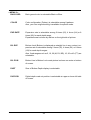
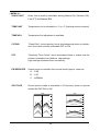
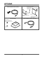
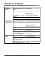
OPERATIONS MANUAL
HE-777
ECHO SOUNDER / FISH FINDER
INTRODUCTION
We thank you very much for purchasing HE-777.
Please be sure to read this operations manual carefully and understand what it describes
before you operate this unit in order to keep your safety.
After you read this manual, please keep it at the place where you will not lose or break and
so as to read soon when it necessary.
In case that you resell or transfer this unit, please give it to the new owner.
We will not be responsible for product liability (PL) law relating to damage to human or
physical property resulted from operation which is not described on this manual or wrong
operation.
DEFINITION OF SYMBOL MARK OF 【CAUTION FOR SAFETY】
DANGER
: Incur the accident resulting in the death or serious wound
unless you keep the descriptions.
WARNING
: Be in danger of incurring the accident resulting in the death or
serious wound unless you keep the descriptions.
CAUTION
: Be in danger or incurring the slight wound to human or damage
to other physical property unless you keep the descriptions.
・ Do not reproduce a part or all of contents described on this manual without our
approval.
・ Please understand that the unit may differ from contents described on this manual
partially due to change of specifications and so on.
・ If you have questions on this manual, may we trouble you to inform us?
CONTENTS
CAUTION ON SAFETY (PLEASE MAKE SURE TO READ.) ............................... 1
HANDLING OF UNIT .......................................................................................... 1
HANDLING OF CABLES .................................................................................... 2
HANDLING OF TRANSDUCER AND WATER TEMPERATURE SENSOR ....... 3
CAUTION ON OPERATION ................................................................................... 4
GENERAL INFORMATION OF ECHO SOUNDER/FISH FINDER ........................ 5
CHECK THE SUPPLIED UNIT AND ACCESSORIES ........................................... 8
DEMENSIONAL DRAWING (DISPLAY) ................................................................ 9
INSTALLATION OF WATER TEMPERATURE SENSOR .................................... 10
CONNECTION WITH DISPLAY UNIT ...................................................................11
INSTALLATION OF THE UNIT............................................................................. 13
HOW TO SEE THE DISPLAY AND DESCRIPTIONS OF CONTROL KEYS ...... 15
POWER ON/OFF OF THE DISPLAY UNIT .......................................................... 16
POWER ON/OFF.............................................................................................. 16
TO USE FOR THE FIRST TIME AFTER PURCHASING ................................. 17
ECHO SIMULATION ......................................................................................... 17
TO SET THE SENSITIVITY .............................................................................. 18
TO SET THE DEPTH ....................................................................................... 20
TO CHANGE THE DISPLAY MODE................................................................. 22
SHIFT ............................................................................................................... 23
SETTING THE FUNCTION BY MENU ................................................................. 24
MENU LIST AND IT’S INDICATION METHOD ................................................. 24
TO SELECT MENU ITEM ................................................................................. 25
FUNCTIONS WHICH CAN BE SET BY MENU ................................................ 26
SWEEP......................................................................................................... 26
AUTO GAIN .................................................................................................. 26
AUTO R/S..................................................................................................... 26
A-MODE ....................................................................................................... 26
SCALE LINE ................................................................................................. 26
TEMP GRPH ................................................................................................ 26
ALARM ......................................................................................................... 27
PICTURE ...................................................................................................... 27
BACK GRD ................................................................................................... 28
COLOR ......................................................................................................... 28
EXP RATE .................................................................................................... 28
B/L EXP ........................................................................................................ 28
B/L POSI....................................................................................................... 28
DIGIT ............................................................................................................ 28
DIG POSI ..................................................................................................... 28
SCALE UNIT ................................................................................................ 29
TEMP UNIT .................................................................................................. 29
TEMP ADJ .................................................................................................... 29
C-ECHO ....................................................................................................... 29
STC .............................................................................................................. 29
PW REDUCER ............................................................................................. 29
SPLIT SCR ................................................................................................... 29
DISPLAY ....................................................................................................... 30
RESET.......................................................................................................... 30
OPTIONS .............................................................................................................. 31
TROUBLE SHOOTING ........................................................................................ 32
SPECIFICATIONS ................................................................................................ 34
CAUTION ON SAFETY (PLEASE MAKE SURE TO READ.)
This section explains the important cautions in order to prevent the person who will use our product or other
persons from human damage or damage to their property.
HANDLING OF UNIT
DANGER
• High voltage is applied to the inside of unit.
No one besides authorized technician should disassemble or modify it.
Unless you keep it, the accident resulting in the electric shock will occur.
* Please be sure to consult with dealer when you want to repair.
WARNING
• Do not install it simply.
It causes to the accident like human damage.
* Please be sure to install correctly according to descriptions on "Installation of the
unit" of this manual.
• Do not use the information displayed on the screen of unit for navigation directly.
It causes to the marine disaster.
* Please be sure to use the official marine charts for navigation judgement.
• Do not operate the unit when you operate the boat.
It causes to the marine disaster.
* Please be sure to operate it after due confirming the surrounding safety.
• Do not put the power on in the presence of flammable materials.
It causes to firing.
• Do not use the power supply besides the specified ones.
It causes to heating or firing.
1
HANDLING OF CABLES
WARNING
• Be sure to use the specified power supply cable.
It causes to heating or firing.
• Do not leave the power plug as it is while it is pulled out of the unit.
If the plug gets well, it causes to heating or firing due to short circuited.
• Be sure to wire in order to prevent the cables from interfering to operate boat.
If feet of crews or operating equipments are caught in cables, it causes to the accident.
* Do not put the heavy objects on cables or do not bend cables excessively.
• Do not disassemble or modify the cables.
It causes to heating, firing or electric shock.
• Do not use the damaged cables.
It causes to firing or electric shock.
CAUTION
• Do not pull the cable when you pull out the plug.
It causes to firing or electric shock because the cable is broken.
* When you pull out the plug, be sure to have it in your hand and pull it.
2
HANDLING OF TRANSDUCER AND WATER TEMPERATURE SENSOR
DANGER
• Work on the bard is too unstable and risky.
Installation and maintenance of transducer and water temperature sensor should be
done after you land and fix the boat.
Unless you keep it, human damage resulting in death or serious wound will occur.
WARNING
• Installation of the transducer or water temperature sensor inside the hull with adhesive should be done while you ventilate well inside the boat.
Volatile gas from solvent or etc. causes to toxic symptoms.
• When you work using electric tools, please keep your hands dry.
If your hands are wet, it causes to electric shock.
• When you pull out or insert the plug of transducer or water temperature sensor,
please be sure to turn the power switch off.
It causes to electric shock.
• Perfect waterproof treatment should be done when you install the transducer or
water temperature sensor through the hull.
If waterproof is not sufficient, It causes to marine disaster because water come in.
3
CAUTION ON OPERATION
Be sure to put the power switch off when you start to run the engine!
When the engine starts to run, voltage of battery varies heavily. It may influence to the
unit.
Be sure to put the power switch of the unit off when you start to run the engine.
Power supply should be 11~35VDC!
Please operate the unit at 11~35VDC of power supply voltage.
Avoid the place where it is high temperature!
When temperature of the unit exceeds 70 C it causes to faulty. Please be more
careful to operate or store it under direct sun ray in the summer time and use it carefully
where it is in the shade as possible.
Prohibited to use the organic solution!
Do not clean this unit with organic solution like thinner, alcohol or etc. as some
parts of the unit and panel are coated or made by plastic. In case it is too dirty, soak the
soft cloth in a synthetic detergent and clean with it after wringing well.
Be careful for water-spray!
Water-spray on the unit causes to faulty. Install at the place where there is no waterspray.
4
GENERAL INFORMATION OF ECHO SOUNDER/FISH FINDER
THEORY OF ECHO SOUNDER/FISH FINDER
• Theory of echo sounder/fish finder is same as echo.
Ultrasonic pluses transmitted from the transducer into the water are reflected from fish school or the sea
bottom and then they are received by transducer.
Echo sounder/fish finder converts round-trip time between the time the ultrasonic wave is transmitted and
the time the reflected wave is received into distance and measures the depth. It displays size or density of
fish school, the outline of bottom or nature of bottom on the screen in different colors.
Transducer
Round trip
0.5 sec.
Round trip
1.0 sec.
The speed at which the ultrasonic wave propagates in
water is approximately 1,500mper second.
For example, in case of roundtrip time between
transmission and reception is 1 sec. to sea bottom and
0.5 sec. to fish school,
Distance to sea bottom......
Reflected wave
from fish school
1,500m (1 sec.)
= 750m
2 (round-trip)
Reflected wave
from sea bottom
Distance to fish school......
750m (0.5 sec.)
= 375m
2 (round-trip)
• Displayed image
Each time when image is sent by one line to the left, ultrasonic wave is transmitted and it’s reflected echo is
displayed on the right edge screen. By repeating this, image is formed.
0m
10m
20m
30m
40m
5
HOW TO DISTINGUISH THE FISH SCHOOL
• Importance is comparison between display of fish school and catch
It is possible to distinguish the fish sort by display of fish school to some extent. But even if fish sort is same,
it’s form making school is different according to difference of fishing ground and difference of time (day and
night, four seasons, variation of current).
The important thing to distinguish the fish sort is to know the sort according to their fishing ground or fishing
period and to find the useful point on the display by comparing between display of fish school and actual
catch.
HOW TO DISTINGUISH THE FISH VOLUME
• Fish volume can be distinguished by density and size of fish school
As the harder density the transmitted wave is reflected strongly, you can distinguish the density of fish
school according to the strength of reflected echo (that is, different color). Normally we tend to think the
larger fish school on the screen the most fish volume. But when fish school are located at the shallow depth
and the deep depth, fish school at the deep depth is displayed bigger than at the shallow depth. Because the
transmitted wave spreads wider as it goes deeper and the reflected wave spreads wider as it goes shallower. As this result, the deeper depth becomes the wider the width of fish school becomes on the screen.
The important thing to distinguish the fish volume is to judge it according to size of fish school and the
strength of reflected echo (color) while you keep “the deeper fish school stays the bigger picture is displayed” in your mind.
Reflected
wave
Fish school A picture
(shallow)
Fish school A
Fish school B picture
(deep)
Fish school B
6
HOW TO DISTINGUISH THE NATURE OF BOTTOM
• There are different natures of bottom such as rock, sand, mud or etc.
In case you distinguish the nature of bottom, you judge from the thickness of bottom image and the situation
of second reflection. At the hard bottom like rock, reflection of transmitted wave becomes strong and bottom
image becomes thick and the second reflection becomes easily to appear. On the other hand, at the soft
bottom like sand or mud the reflection becomes weak and bottom image becomes thin and the second
reflection becomes hard to appear.
*Second reflection .......... Ultrasonic wave transmitted from transducer is reflected from sea bottom and
then it is reflected from both sea surface and bottom finally. In short, second reflection is image of two round-trips between sea surface and bottom.
Sand or mud
Rock
Second reflection
7
CHECK THE SUPPLIED UNIT AND ACCESSORIES
Please check if all of the below-described items are packed when you use the unit for the first time.
Display Unit (with bracket) (1)
Power Supply cable (1)
Operations manual (1)
Fuse (10A) (1)
Disk Plate (6)
Screw for installing bracket (6)
M6X20
Screw
8
DEMENSIONAL DRAWING (DISPLAY)
308
: mm
A
A
254
276
340
A
A
278
335
<Drawing of holes for installing bracket>
11
11
11
11
170
6-φ9
8-φ6
A∼A
100
100
120
200
Confirm no obstacles in this area.
9
INSTALLATION OF WATER TEMPERATURE SENSOR
*Water temperature sensor is option.
DANGER
• Work on the board is too unstable and risky.
Installation and maintenance of the water temperature sensor should be done after
you land and fix the boat.
Unless you keep it, human damage resulting in death or serious wound will incur.
WARNING
• Perfect water proof treatment should be done when you install the water temperature sensor through the hull.
Unless perfect, it causes to marine disaster due to inundation.
• When you work using electric tools, please keep your hands dry.
If your hands are wet, it causes to electric shock.
<Installation of thru-hull water temperature sensor (TC02C)>
Water temperature sensor
Cork packing
Nut (2 pcs.)
FRP
Washer
FRP
Perfect water-proof treatment should
be done at the joining position.
Rubber packing
10
CONNECTION WITH DISPLAY UNIT
Transducer
5P
8P
6P
2P
NMEA
(GGA,VTG)
Output
Fuse Holder(10A)
Temp. Sensor
(Option)
B (-)
W (+)
Battery
(11~35V DC)
11
1. Transducer (5-P)
1
2
3
Low F
2
4
High F
1
5
1
3
2
4
3
5
4
6
5
7
2. Data In/Out (6-P)
5V
1
3
4
2
6
5
1
1.
2.
3.
4.
5.
6.
GND
RXD-C
RXD-H
N.C.
TXD
DC12V out (max. 200mA)
2
3
1k
470Ω
4
5
6
DATA OUT (RS232CLEVEL)
+ For EXTERNAL POWER
12V DC, 200mA (max.)
-
3. Temperature (8-P)
4
3
5
6 8 2
7
1
1. N.C.
2. N.C.
3. N.C.
4. N.C.
5. N.C.
6. (+)
7. (-)
8. N.C.
4. Power Supply
2
1
1. (+) 11~35VDC
2. (-)
12
INSTALLATION OF THE UNIT
WARNING
• Do not install it simply.
If your hands are wet, it causes to electric shock.
It causes to the accident like wound.
* Please install correctly according to [Installation of the unit].
<Procedure of installation>
1. <Selection of installation method> Unit is supplied in Portrait.
a. Installation in Portrait: Remove lower bracket by loosing 2 pcs. Hexagon bolts (M8X20) in front of the
bracket. Go to procedure 2.
Hexagon bolt
M8X20
b. Installation in Landscape: After procedure 1 a, remove upper bracket by loosing 6 pcs. Pan head screws
with spring washers (M6X10)and install them on the side of display unit.
TO CHANGE DISPLAY STYLE, Call menu 3 and set Portrait, Portrait Reverse, Landscape or Landscape
Reverse.
After setting the unit, make sure to seal unused 6 holes by stickers to prevent damages from splash, etc.
Pan head screw
with spring washer
M6X10
13
2. <Fixing the lower bracket>
After you decide the location to install the unit, fix the lower bracket with 6 pcs. screws M6X20 which are
supplied with the unit. Refer to [Dimensional drawing] for the position of holes.(Page 9)
Bolt
M8X35
Screw
M6X20
8mm
S-Washer
8mm
Washer
M8 HEX. Nut
IMPORTANT NOTICE
When you install the unit on the ceiling, DO NOT USE pan head screws supplied with the unit.
You must use hexagon bolts (bigger than M8X35) and install firmly.
3. <Putting the disk plate>
Put the supplied disk plates on six holes which are not used for installing the unit to prevent the water or
foreign substance from entering.
Disk plate
X6
4. <Installing the unit>
Put the unit on so that the rear of it’s upper bracket could fit in inner bento position at rear of lower bracket.
And then, fix the front of bracket with 2 pcs. hexagon bolt (M8X20).
HEX. Bolt
M8X20
14
HOW TO SEE THE DISPLAY AND DESCRIPTIONS OF CONTROL KEYS
*1 Longitude
*1 Latitude
*1 Bearing
*1 Boat Speed
*3 Auto Range Mark
*2 Water Temp.
Depth
N 34°43.356
E 137°37.456
Gain
0
341°
17.8N
18.0℃
AR
Range
17.5
Color Bar
10
Mode
Fish Mark
Menu
20
Shift
FIRST
BOTTOM
ECHO
SECOND
BOTTOM
ECHO
m
30
50 G3.0
200 G3.0
Depth Unit
4
Power/Brightness
FREQUENCY
*4 GAIN LEVEL
SWEEP SPEED
REMARKS;
*1: To be shown when “NMEA(GGA, VTG)” is connected.
*2: To be shown when “Temp. Sensor (Option)” is connected.
*3: AR is shown when “Auto Range” is set.
AS is shown when “Auto shift” is set.
*4: “G AUTO” is shown when “Auto Gain” is set.
15
POWER ON/OFF OF THE DISPLAY UNIT
POWER ON/OFF
CAUTION
• Please be sure to turn the power on after you start the engine of boat to prevent the
malfunction of unit or damage to memory contents.
MEMO:
When you use the unit for the first time, please read “TO USE FOR THE FIRST
TIME AFTER PURCHASING”
1. By rotating POWER & BRIGHT switch clockwise, a sound like
“piroro” sounds and power is turned on.
Adjust the brightness with rotating this switch.
When you turn the power on, version No. of the system and
frequency are shown on the screen.
POWER & BRIGHT switch
2. When you rotate this switch counterclockwise until a “Click” is
heard, power is turned off.
IMPORTANT NOTICE
The HE-777 is designed to use Hondex transducer.
If you use other brand transducer, please ask your local dealer to make sure it
works properly.
16
TO USE FOR THE FIRST TIME AFTER PURCHASING
INPORTANT
In order to protect the unit and transducer from damage, at first, DISCONNECT
transducer from unit.
HE-777 has multi-lingual menu mode. (Factory setting is in English)
Before starting to use the unit, set the menu language first. (English, Japanese, Chinese, Korean, Spanish,
Italian and Thai)
1. Turn the unit power on.
2. Call “Other Setting” menu (See page 24).
3. Set language.
4. Return to sounder mode by menu key.
NOTE: Once you set the language, no need to set again from next time use.
< LANGUAGE >
< OTHER SETTING >
FACTORY SET
BY
KEY
LANGUAGE
[
/
] MENU SETTING
[
TO FINISH MENU
/
] MENU SETTING
PREVIOUS MENU
ECHO SIMULATION
For demonstration purpose, echo simulation is available.
GAIN
key
+
POWER ON!
With pressing GAIN
key, turn the power on and hold the GAIN
key for abaout 3 seconds.
A sound like “piroro” sounds once at first, then after sounding for
3 times like “piroro, piroro, piroro”, echo simulation is shown on
the screen. To finish the echo simulation mode, simply turn the
power off.
17
TO SET THE SENSITIVITY
How to see the sensitivity
N 34°43.356
E 137°37.456
0
341°
17.8N
18.0℃
AR
17.5
10
First
Reflection
20
m
30
50 G3.0
Second Reflection
200 G3.0
1*
4
<Sensitivity>
This adjust the sensitivity to distinguish the bottom or fish school
easily. 101 steps from 0.0 to 10.0 are available. The sensitivity
level is displayed on the bottom of the screen. Optimum setting to
distinguish is that the second reflection of the bottom is displayed
in weaker color and the first reflection of the bottom is shown in
red.
<Second Reflection>
The first received echo reflected from bottom is called the first
reflection (first echo). Generally, at shallow depth, the first reflection (first echo) reflected by the surface of water goes toward the
bottom again. The next reflection from bottom is called the second reflection (second echo). Normally, the second reflection (second echo) is shown at the twice of the actual bottom (first reflection).
1* Sensitivity
It indicates present value of sensitivity. (101 steps from 0.0 to 10.0 can be adjusted.)
18
How to set the sensitivity
AUTO GAIN mode is NOT recommendable when the transducer was installed inside of the hull.
GAIN
key
GAIN
key
<To decrease the sensitivity>
Each time when you press GAIN
key, sensitivity decreases
and number indicating sensitivity decreases.
<To increase the sensitivity>
Each time when you press GAIN
key, sensitivity increases and
number indicating sensitivity increases.
<Poor sensitivity>
<Good>
<Too much sensitivity>
Bottom is shown in green or
white.
As second reflection is shown,
it is easy to distinct the fish
school.
As plankton, stains in water,
and etc.
To set GAIN level in dual frequency mode, press menu key shortly for selecting the frequency.
(Numbers in YELLOW is in action)
19
TO SET THE DEPTH
How to see the depth
N 34°43.356
E 137°37.456
<Depth (Display Range)>
Display ranges from 0-10m to 0-2,000m are available.
2,000m-4,000m by SHIFT is maximum.
0
341°
17.8N
18.0℃
AR
17.5
10
0
1
10
20
15
20
30
40
m
30
50 G3.0
200 G3.0
4
50
60
2
80
100
120
150
180
200
250
300
400
500
600
800
1000
1500
2000m
Depth Read Out
Digital depth read out shows the distance from transducer surface to the bottom.
However, under certain condition, such as “Soft bottom”, “Planktons”, “Big fish school”, etc., it may show uncertain distance(depth). You must check by picture or official chart to make sure the bottom depth, whenever any
uncertain number (depth) is shown.
1. Depth read out is shown at the top or bottom on left side of screen, and its size of number is selectable by
menu 2.
2. Unit of the depth is selectable among Meters, Feet, Fathoms and Brazas by Menu 3.
Digital Read Out ranges are limited as follows:
Deepest number
Depth (Display Range): m
0-
Display range X 2
10m ~ 0- 600m
0- 800m ~ 0-1500m
Display range X 1.5
0- 2000m
Display range X 1.2
IMPORTANT
The maximum detectable depth varies depending upon the water or bottom
condittion.(No relation with maximum depth range)
When in dual frequency (50 & 200kHz) mode, right (upper) frequency has a
priority in parallel display, i.e., right (upper) side: Normal, left (lower) side: EXP.,
B/L or HISTORICAL.
20
How to set the depth
MEMO:
When you set AUTO RANGE, range is automatically changed so that the bottom is
always kept on the optimum position of screen.
AUTO RANGE mode is NOT recommendable when the transducer was installed inside of the hull.
RANGE
key
RANGE
key
<To decrease the depth (display range)>
Each time when you press RANGE
key, the depth decreases
(getting shallower).
0
0
15
10
<To increase the depth (display range)>
Each time when you press RANGE
key, the depth increases
(getting deeper).
21
0
0
10
15
TO CHANGE THE DISPLAY MODE
There are four kinds of display mode. Press MODE key for:
NORMAL
NORMAL + ZONE EXPANSION
NORMAL + B/L EXPANSION
NORMAL + HISTORICAL
1. The rate of EXPANSION and B/L EXPANSION are selectable by Menu 2.
2. In B/L mode, the bottom line positions are selectable, BOTTOM or CENTER of screen by Menu 2.
3. HISTORICAL display shows about 10 times of the sweep speed.
IMPORTANT
In case there is a sharp undulating bottom or bottom is indicated unevenly due
to pitching or rolling, B/L may not be displayed properly.
EXP
NORMAL
B/L
NORMAL
HST
MODE key
N
22
EXP
B/L
HST
NORMAL
SHIFT
SHIFT
0m
0
5m
5
Press SHIFT
10m
10m Shift
key
10
5m
15
Press SHIFT
20m
key
20
5m
25
30m
You can move the display range to the shallower depth or deeper depth without changing the depth (display
range).
MEMO:
When you set AUTO SHIFT, range is automatically shifted.
AUTO SHIFT mode is NOT recommendable when the transducer was installed inside of the hull.
SHIFT
key
SHIFT
key
<To shift to shallow depth>
Each time when you press SHIFT
comes shallow.
key, the display range be-
<To shift to deep depth>
Each time when you press SHIFT
comes deep.
key, the display range be-
23
SETTING THE FUNCTION BY MENU
MENU LIST AND IT’S INDICATION METHOD
Press menu for about 3 seconds.
< MENU 1 >
SWEEP
: FRZ 1 2 3 4 5
AUTO GAIN : OFF L M H
AUTO R/S
: OFF RNG SFT
A-MODE
: OFF ON
SCALE LINE : OFF ON
TEMP GRPH : OFF ON
ALARM
PICTURE
: L H L/H H/L
[
] MENU SETTING
TO NEXT MENU
Press menu
MODE key
MENU key
< MENU 2 >
BACK RGD :BLACK BLUE
COLOR:
OWN SETTING
EXP RATE : X2 X4 X8
B/L EXP
: X2 X4 X8 5 10 20
B/L POSI : BTM CTR
DIGIT
: SMALL LARGE
DIG POSI : UPPER LOWER
TO NEXT MENU
Press menu
Press menu
< MENU 3 >
SCALE UNIT : M FT FA BR
TEMP UNIT
:
TEMP ADJ
C-ECHO
: OFF 1 2
STC
: OFF L M H
PW REDUCER : A B C
SPLIT SCR
: L/R U/L
DISPLAY
: P PR L LR
RESET
TO FINISH MENU
Press menu for about 3 seconds.
Finish menu
< OTHER SETTING >
FACTORY SET BY
KEY
LANGUAGE
[
/
Perss
cursor
] MENU SETTING
< OTHER SETTING >
FACTORY SET
BY
KEY
LANGUAGE
[
/
TO FINISH MENU
Press menu
Finish menu
] MENU SETTING
TO FINISH MENU
Press mode
Press menu
< LANGUAGE >
[
/
] MENU SETTING
PREVIOUS MENU
24
TO SELECT MENU ITEM
Menu item is selected moving cursor (in yellow square) with Select
Selected item is covered with frame.
, Select
, Set
or Set
key.
Installation Portrait
Select
key
Select
key
Set
key
Set
key
Installation Landscape
Select
key
Select
Set
key
25
Set
key
key
FUNCTIONS WHICH CAN BE SET BY MENU
Functions:
The following functions are selectable and set by cursor.
< MENU 1 >
SWEEP
Picture moving speed is selectable.
FRZ : Stop
1 : Slowest
:
:
5 : Fastest
AUTO GAIN
OFF : Manual control.
L : Low Gain Setting.
M : Medium Gain Setting.
H : High gain Setting.
AUTO R/S
OFF : Manual control.
RNG : Depth Range is automatically changed by bottom depth.
SFT : Picture is automatically shifted with the same scale at any depth.
A-MODE
Selectable OFF or ON.
SCALE LINE
Scale Line is selectable OFF or ON.
TEMP GRPH
Temperature Graph is selectable OFF or ON.
(Optional sensor required)
26
ALARM
Press Mode key to go ALARM setting mode.
Shallow, Deep, Zone and Anchor alarms are available.
SETTING THE FANCTION BY MENU
Call menu 1.
Set cursor to ALARM.
Press MODE.
Set ALARM ON.
Alarm on
For SHALLOW alarm setting;
Set shallow limit depth by RANGE key with watching RED BAR
on the right edge of sounder image.
For DEEP alarm setting;
Set deep limit depth by RANGE key with watching RED BAR on
the right edge of sounder image.
For ZONE alarm setting;
Set shallow and deep limits by RANGE key with watching RED
BAR on the right edge of sounder image.
Shallow
Alarm on
Deep
Alarm on
For ANCHOR alarm setting;
Set shallow and deep limits by RANGE key with watching RED
BARs on the right edge of sounder image.
Zone
Alarm on
To select ALARM LEVEL;
Set the cursor to LEVEL and select echo level to activate ALARM.
Alarm on
Set MENU to exit menu mode.
PICTURE
Anchor
In dual frequency mode, display mode (Frequency) is selectable.
L : Lower Frequency only
H : Higher Frequency only
L/H : Lower Frequency is in Left half
Higher Frequency is in Right half
H/L : Higher Frequency is in Left half
Lower Frequency is in Right half
27
< MENU 2 >
BACK GRD
Back ground color is selectable Black or Blue.
COLOR
Color configuration (Pattern) is selectable among 8 patterns.
Also, your own original setting is available for special mode.
EXP RATE
Expansion rate is selectable among 2 times (X2), 4 times (X4) or 8
times (X8) for each depth range.
Expanded area is shown by red bar on the right side of picture.
B/L EXP
Bottom Lock (Bottom is displayed as straight line in any contour) expansion rate is selectable among 2 times (X2), 4 times (X4) or 8 times
(X8) for each depth ranges.
Also, fixed ranges such as 5, 10, 20 (M, FA, BR), 10, 20 or 40 (FT) are
selectable.
B/L POSI
Bottom Line in Bottom Lock mode picture is shown on center or bottom
of screen.
DIGIT
Size of Bottom Depth display is selectable.
DIG POSI
Digital depth read out position is selectable at upper or lower left side
of screen.
28
< MENU 3 >
SCALE UNIT
Scale unit in depth is selectable among Meters (M), Fathoms (FA),
Feet (FT) and Brazas (BR).
TEMP UNIT
Temperature unit is selectable in C or F (Optional sensor required).
TEMP ADJ
Temperature fine adjustment is available.
C-ECHO
“Clean Echo” (noise rejecter) circuit eliminates small noise or interference from other sounder, selectable OFF or ON.
STC
“Sensitivity Time Control” circuit eliminates clutters or noises near the
surface, selectable Low, Medium, High settings.
High settings eliminates them excessively.
PW REDUCER
Output power is reducible from normal mode. Approx. rates are;
A : 1/3B
B : 1/3C
C : NORMAL
SPLIT SCR
Screen picture mode is selectable in 2-Frequency mode or special
modes like EXP, B/L or HIS.
L/R:
U/L:
0
0
2
2
4
6
4
6
8
10
0
2
8
4
6
10
8
10
29
DISPLAY
Display mode is selectable.
P: Portrait
PR: Portrait Reverse
L: Landscape
RESET
LR: Landscape Reverse
Return to First setting mode.
30
OPTIONS
Water temperature sensor (TC02C)
In-dash plate (WP04)
Reinforcement
metal plate X 2
Bolt (M8 X 40)
X4
Frame X 1
Metal plate (Right & Left)
X 1 each
Sun hood (SF05)
Mushroom tapping screw
(M5 X 20) X 4
Water temperature extension cable (EK11)
M4 X 8 SUS
Mushroom head screw
(black coating on top) X 4
Collar X 4
31
TROUBLE SHOOTING
When the condition of this unit is bad, please check the following points before asking to repair;
Symptoms
Power can not be
turned on.
Causes
Remedy
Voltage of battery is lower than standard Recharge the battery.
value (11V).
Contact of power connector is poor.
Tighten firmly. Clean and remove the rust, dust,
etc. In case of corrosion, please replace.
• Replace power supply cable.
• Replace the connector.
Incorrect connection of power cable to Check the polarity and connect correctly.
boat battery.
Wire inside power cable is cut.
Replace the polarity and connect correctly.
Blown fuse.
Replace fuse (10A).
No display on th screen. Brightness control is set to minimun.
Adjust the brightness control. (Refer to page16)
Bottom or fish school Contact of transducer connector is bad.
can not be displayed at
all.
Connect surely. Clean the surface of
transducer and remove the rust, stain, or etc.
Replace in case of corrosion.
• Replace in case of corrosion.
• Replase connector on the unit (ask to repair).
Select the correct frequency on.
Frequency is wrong.
Transducer is not immersed into water Install the transducer where it is always
immersed in water.
well.
In case of installing the transducer inside Supplement liquid so that transducer can be
the hull, it is not immersed into water immersed into water.
because internal liquid becomes less.
Image does not appear Transducer is not immersed into water Install the transducer where it is always
sometimes.
immersed under the waterline.
well.
When installation of transducer is bad, Check the installation of transducer.
air bubbles wind is easily at high speed
sailing. It results in no display.
Influence of air bubble when the boat Move the own boat or wait until air bubbles
disappear.
runs across the wakes of another boat.
32
Symptoms
Causes
Remedy
Increase the sensitivity.
Or set Auto Gain.
Bottom or fish school is Too low sensitivity.
not displayed well.
Weeds, barnacles, oyster shell, rubbish Remove the attachment well.
or etc. attach on the surface of
transducer.
Install it inside the hull, bottom or liquid is Remove the stain on the bottom. Replace the
dirty.
liquid.
As the reflected echoes are very weak at the below described place, the image low
sensitivity may be shown.
But it is not trouble.
where there are
many sludge.
where there are
many sea weeds.
Many noise appears on Too high sensitivity.
the display.
where there are
many mud or
rubbish.
where the water is
whirled by rapid
current.
Decrease the sensitivity.
Or set Auto Gain.
Interference with other boat's fish finder.
Noise disappears if the adequate distance
between own boat and other keeps.
Noise from engine.
Change the routing of cables like transducer
cable, power supply cable or etc. (Separate
from engine as far as possible.)
33
SPECIFICATIONS
DISPLAY
PIXELS
VOLTAGE
POWER CONSUMPTION
SIZE
WEIGHT
OUTPUT POWER
FREQUENCY
GAIN
RANGE
SHIFT
MODE
IMAGE STYLE
MENU
SPLIT SCREEN
EXPANSION
B/L EXP.
SWEEP SPEED
AUTO GEIN
AUTO RANGE/SHIFT
CLEAN ECHO
STC
POWER REDUCER
UNIT
B.G.COLOR
COLOR CONFIGURATION
CALIBRATION LINE
A-MODE
NMEA0183 INPUT
NMEA0183 OUTPUT
ALARM
10” Color CRT
320X240
11-35VDC
60W
308X254X340mm w/bracket
9.4Kgs approx.
600W
50&200KHz Simultaneous Soundings
101 steps
10, 15, 20, 30, 40, 50, 60, 80, 100, 125, 150, 180, 200,
250, 300, 400, 500, 600, 800, 1000, 1500, 2000
(m, Ft, Fa, Br)
2000-4000 Max.
L+H, H/EXP+H, H/BL+H, H/HIS+H or
H+L, L/EXP+L, L/BL+L, L/HIS+L
Portrait/P-Reverse, Landscape/L-Reverse
English, Italian, Spanish, Thai, Korean, Chinese
side/side or upper/lower
X2, X4, X8
X2, X4, X8 or 5/10/20 (M, FA, BR), 10/20/40 (Ft)
Freeze, 1/2/3/4/5
Off/L/M/H
Off/Range/Shift
Off/1/2
Off/W/M/S
L/M/H
M/Fa/Ft/Br/Hiro
Black/Blue
8 kinds
Off/On
Off/On
GGA (L/L), VTG (Speed/Direction)
DBT (Depth), MTW (Temp)
Shallow, Deep, Zone, Anchor
34