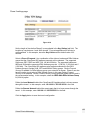
1
CyberGuard SG User Manual CyberGuard 7984 South Welby Park Drive #101 Salt Lake City, Utah 84084 Email: [email protected] Web: www.cyberguard.com Revision 2.1.5 July 21st, 2005 Contents 1. Introduction...............................................................................................1 CyberGuard Gateway Appliances (SG3xx, SG5xx Series) ................................... 1 CyberGuard Rack Mount Appliances (SG7xx Series) ........................................... 2 CyberGuard PCI Appliances (SG6xx Series) ........................................................ 3 Document Conventions ......................................................................................... 5 Your CyberGuard Gateway Appliance................................................................... 6 CyberGuard Gateway Appliance Features ............................................................ 8 Your CyberGuard SG Rack Mount Appliance ....................................................... 9 CyberGuard SG Rack Mount Appliance Features ............................................... 11 Your CyberGuard SG PCI Appliance................................................................... 12 CyberGuard SG PCI Appliance Features ............................................................ 13 2. Getting Started........................................................................................14 CyberGuard SG Gateway Appliances ................................................................. 15 Set up a PC to Connect to the Web Management Console ................................ 15 Set up the Password and LAN Connection Settings ........................................... 17 Set up Internet Connection Settings .................................................................... 21 Set up the CyberGuard SG Appliance’s Switch................................................... 22 Set up the PCs on your LAN to Access the Internet ............................................ 23 CyberGuard SG Rack Mount Appliances ............................................................ 28 Set up a PC to Connect to the Web Management Console ................................ 28 Set up the Password and LAN Connection Settings ........................................... 31 Set up Internet Connection Settings .................................................................... 34 Set up the PCs on your LAN to Access the Internet ............................................ 35 CyberGuard SG PCI Appliances ......................................................................... 40 Install your CyberGuard SG Appliance in a Spare PCI Slot ................................ 40 Install the Network Driver on your PC.................................................................. 40 Set up your PC to Connect to the Web Management Console ........................... 40 Set up the Password and Network Connection Settings ..................................... 42 Disabling the Reset Button on your CyberGuard SG PCI Appliance................... 48 3. Network Connections.............................................................................49 Connections......................................................................................................... 49 Multifunction vs. Fixed-function Ports .................................................................. 50 LAN Connection................................................................................................... 52 Internet Connection ............................................................................................. 53 Primary Internet Connection ................................................................................ 54 Secondary Internet Connection ........................................................................... 56 Internet Load Balancing....................................................................................... 57 Internet Failover................................................................................................... 58 DMZ Connection.................................................................................................. 61 Services on the DMZ Network ............................................................................. 62 Guest Connection ................................................................................................ 62 Wireless ............................................................................................................... 64 COM/Modem ....................................................................................................... 68 Bridging................................................................................................................ 68 Routes ................................................................................................................. 68 Advanced............................................................................................................. 68 QoS Traffic Shaping ............................................................................................ 68 VLANs.................................................................................................................. 68 Port Based VLANs............................................................................................... 68 4. Dialin Setup .............................................................................................68 Dialin Setup ......................................................................................................... 68 Dialin User Accounts ........................................................................................... 68 Account list .......................................................................................................... 68 Remote User Configuration ................................................................................. 68 5. DHCP Server ...........................................................................................68 DHCP Server Configuration................................................................................. 68 DHCP Proxy ........................................................................................................ 68 6. Firewall ....................................................................................................68 Incoming Access.................................................................................................. 68 CyberGuard SG Administrative Web Server ....................................................... 68 Packet Filtering .................................................................................................... 68 NAT...................................................................................................................... 68 Rules.................................................................................................................... 68 Universal Plug and Play Gateway ....................................................................... 68 Port Tunnels ........................................................................................................ 68 Access Control and Content Filtering .................................................................. 68 7. Intrusion Detection .................................................................................68 Basic Intrusion Detection and Blocking ............................................................... 68 Advanced Intrusion Detection.............................................................................. 68 8. Web Cache ..............................................................................................68 Web Cache Setup................................................................................................ 68 Network Shares ................................................................................................... 68 Peers ................................................................................................................... 68 Set up LAN PCs to Use the Web Cache ............................................................. 68 9. Virtual Private Networking .....................................................................68 PPTP Client Setup............................................................................................... 68 PPTP Server Setup ............................................................................................. 68 IPSec Setup......................................................................................................... 68 Set up the Branch Office...................................................................................... 68 Configuring the Headquarters.............................................................................. 68 Tunnel List ........................................................................................................... 68 NAT Traversal Support ........................................................................................ 68 Dynamic DNS Support......................................................................................... 68 Certificate Management....................................................................................... 68 Troubleshooting ................................................................................................... 68 GRE ..................................................................................................................... 68 L2TP .................................................................................................................... 68 10. USB ..........................................................................................................68 USB Mass Storage Devices ................................................................................ 68 USB Printers ........................................................................................................ 68 Printer Troubleshooting ....................................................................................... 68 USB Network Devices and Modems.................................................................... 68 11. System.....................................................................................................68 Date and Time ..................................................................................................... 68 Users ................................................................................................................... 68 Diagnostics .......................................................................................................... 68 Advanced............................................................................................................. 68 Technical Support................................................................................................ 68 Appendix A – IP Address Ranges..................................................................68 Appendix B – Terminology.............................................................................68 Appendix C – System Log ..............................................................................68 Access Logging ................................................................................................... 68 Creating Custom Log Rules................................................................................. 68 Rate Limiting........................................................................................................ 68 Administrative Access Logging............................................................................ 68 Boot Log Messages ............................................................................................. 68 Appendix D – Firmware Upgrade Practices and Precautions .....................68 Appendix E – Recovering From a Failed Upgrade .......................................68 1. Introduction This chapter provides an overview of your CyberGuard SG appliance’s features and capabilities, and explains how to install and configure your CyberGuard SG appliance. This manual describes how to take advantage of the features of your CyberGuard SG appliance, including setting up network connections, a secure firewall and a VPN. It also describes how to set up the CyberGuard SG appliance on your existing or new network using the Web Management Console web administration pages. CyberGuard Gateway Appliances (SG3xx, SG5xx Series) The CyberGuard SG3xx, SG5xx appliance range (SG300, SG530, SG550, SG560, SG565, SG570, SG575, SG580) enables your office LAN to share a single, secure Internet connection. The CyberGuard SG appliance provides Internet security and privacy of communications for small and medium enterprises. It simply and securely connects your office to the Internet, and with its robust stateful firewall, shields your computers from outside threats. The CyberGuard SG appliance checks and filters data packets to prevent unauthorized intruders gaining access. The CyberGuard SG appliance’s NAT/masquerading firewall means that although computers on your office network can see and access resources on the Internet, all outsiders see is the CyberGuard SG appliance’s external address. CyberGuard SG appliance models SG570 and SG575 have an additional Ethernet port that may be configured as a physically separate DMZ to host servers accessible to the outside world, in order to further secure your local network. Alternatively, it may be configured as a second Internet connection to use as a backup Internet connection should the primary link become unavailable, or to use simultaneously to perform network load balancing. The CyberGuard SG appliance provides you with a Virtual Private Network (VPN) server. A VPN enables remote workers or branch offices to securely access your company network to send and receive data at a very low cost. With the CyberGuard SG appliance, you can remotely access your office network securely using the Internet. The CyberGuard SG appliance can also connect to external VPNs as a client. 1 Introduction The following figure shows how your CyberGuard SG appliance interconnects. Figure 1-1 CyberGuard Rack Mount Appliances (SG7xx Series) The CyberGuard SG710/SG710+ is the flagship of CyberGuard’s SG series. It features multi-megabit throughput, rack-optimized form factor, two fast Ethernet ports and two 4port fast Ethernet switches as standard, and the option for two additional gigabit ports (SG710+). Each of these four (or six with the SG710+) can be configured as a LAN, DMZ or Internet connection. Dual Internet connections can be configured for use simultaneously for network load balancing between the links, or to keep one in reserve as a back up Internet connection should the primary Internet connection become unavailable. Additionally, the SG710/SG710+ incorporates a powerful web proxy cache to improve web page response time and reduce link loads. It is designed to integrate seamlessly with upstream proxy caches provided by ISPs. Bandwidth can be further optimized through traffic shaping controls, making it excellent for organization that are power web users or have many remote offices accessing corporate intranets. Customers wishing to protect against access to inappropriate web material can purchase an URL content filtering (UCF) subscription service. This works in conjunction with the URL proxy embedded in the CyberGuard SG710/SG710+ to increase productivity and available bandwidth. The combination supports blocking, monitoring, rating and optional reporting without the need for an on-site URL database. The CyberGuard SG710/SG710+ features a powerful, fully configurable firewall, advanced intrusion detection and the ability to actively enforce network security policies to protect your network. 2 Introduction It provides central sites the capacity to securely connect hundreds of mobile and remote employees. The SG710/SG710+ includes a high-performance, VPNC-certified VPN solution for securely connecting branch office networks to the corporate hub using IPsec, PPTP, L2TP, and other industry-standard protocols. Onboard cryptographic acceleration ensures excellent VPN throughput. CyberGuard PCI Appliances (SG6xx Series) The CyberGuard SG PCI appliance (SG630, SG635) is a hardware-based firewall and VPN server embedded in a 10/100 Ethernet PCI network interface card (NIC). It is installed into the host PC like a regular NIC, providing a transparent firewall to shield the host PC from malicious Internet traffic, and VPN services to allow secure remote access to the host PC. This appliance is recommended for: • Security conscious businesses that wish to separate firewall and VPN issues from server/desktop operating systems. • Businesses that wish to eliminate the "soft center". • For environments where the integrity of the host server operating environment cannot be controlled or trusted. Unlike other CyberGuard SG appliances, a single CyberGuard SG PCI appliance it is not intended as a means for your entire office LAN to be connected to, and shielded from, the Internet. Installing a CyberGuard SG appliance in each network connected PC gives it its own independently manageable, enterprise-grade VPN server and firewall, running in isolation from the host operating system. This approach offers an increased measure of protection against internal threats as well as conventional Internet security concerns. You can update, configure and monitor the firewall and VPN connectivity of a workstation or server from any web browser. In the event of a breach, you have complete control over individual PCs' access policies independent of the host PC's operating system, even if the system has been subverted and is denying normal administrator access. All network filtering and what can be CPU intensive cryptographic processing is handled entirely by the CyberGuard SG appliance. This has the advantage over the traditional approach of a host-based personal software firewall and VPN services of not taxing the host PC's resources. 3 Introduction Bridged mode By default, the CyberGuard SG PCI appliance operates in bridged mode. This is distinctly different from the NAT/masquerading behavior of the CyberGuard SG gateway appliance range. In bridged mode, the CyberGuard SG appliance uses two IP addresses. Note that these addresses are both in the same range as the LAN, as no NAT/masquerading is being performed (see the chapter entitled Firewall for more information). One IP address is used to manage the CyberGuard SG appliance via the Web Management Console web administration pages. The other is the host PC's IP address, configurable through the host operating system identical to a regular NIC. This is the IP address that other PCs on the LAN see. It should be dynamically (DHCP) or statically configured to use the same gateway, DNS, etc. settings as a regular PC on the LAN. It is possible to configure the CyberGuard SG PCI appliance to run in NAT mode. This is discussed in the chapter entitled Network Connections. Secure by default By default, all CyberGuard SG appliances run a fully secured stateful firewall. This means from the PC that it is plugged into, most network resources are freely accessible. However, any services that the PC provides, such as file shares or web services (e.g. IIS) will not be visible to the general office LAN without further configuration of the CyberGuard SG appliance. For details on how services on the host PC can be made available to the general office LAN, see the section Allowing individual ports in bridged mode at the end of the chapter entitled Firewall. 4 Introduction Document Conventions This document uses different fonts and typefaces to show specific actions. Warning/Note Text like this highlights important issues. Bold text in procedures indicates text that you type, or the name of a screen object (e.g. a menu or button). 5 Introduction Your CyberGuard Gateway Appliance CyberGuard gateway appliances include: • SG300 • SG530 • SG550 • SG560 • SG565 • SG570 • SG575 • SG580 The following items are included with your CyberGuard SG appliance: • Power adaptor • Installation CD • Printed Quick Install guide • Cabling including o 1 normal straight through UTP cable (blue color). o 1 crossover UTP cable (either gray or red color) Note The SG300 model includes two blue straight through UTP cables. Front panel LEDs The front and rear panels contain LEDs indicating status. An example of the front panel LEDs are illustrated in the following figure and detailed in the following table. Figure 1-2 6 Introduction Note Not all the LEDs described below are present on all CyberGuard SG appliance models. Also, labels vary from model to model. Label Activity Description Power On Power is supplied to the CyberGuard SG appliance Heart Beat Flashing The CyberGuard SG appliance is operating correctly On If this LED is on and not flashing, an operating error has occurred LAN Activity Flashing Network traffic on the LAN network interface WAN Activity Flashing Network traffic on the Internet network interface WLAN Flashing Network traffic on the Wireless network interface DMZ Activity Flashing Network traffic on the DMZ network interface Serial Activity Flashing For either of the CyberGuard SG appliance COM ports, these LEDs indicate receive and transmit data HA On Reserved to indicate failover to a backup device (available in a future firmware release) Online On An Internet connection has been established VPN On Virtual Private Networking is enabled Online On An Internet connection has been established Note If Heart Beat does not begin flashing shortly after power is supplied, refer to Appendix E, Recovering From a Failed Upgrade. Rear panel The rear panel contains network and serial connector ports, the Reset/Erase button and power inlet. If network status LEDs are present, the lower or left LED indicates the link condition, where a cable is connected correctly to another device and the upper or right LED indicates network activity. 7 Introduction CyberGuard Gateway Appliance Features Internet link features • 10/100baseT Ethernet port • Serial port • Front panel serial status LEDs (for TX/RX) • Online status LEDs (for Internet/VPN) • Rear panel Ethernet link and activity status LEDs LAN link features • 10/100BaseT LAN port (SG530, SG550) • 10/100BaseT 4 port LAN switch (SG300) • 10/100BaseT 4 port VLAN-capable switch (SG560, SG565, SG580) • Rear panel Ethernet link and activity status LEDs DMZ link features (SG570, SG575 only) • 10/100BaseT DMZ port • Real panel Ethernet link and activity status LEDs Enviromental features • External power adaptor (voltage/current depends on individual model) • Front panel operating status LEDs: Power, Heart Beat • Operating temperature between 0° C and 40° C • Storage temperature between -20° C and 70° C • Humidity between 0 to 95% (non-condensing) 8 Introduction Your CyberGuard SG Rack Mount Appliance CyberGuard SG rack mount appliances include: • SG710 • SG710+ The following items are included with your CyberGuard SG rack mount appliance: • Power cable • Installation CD • Printed Quick Install guide • Cabling including o 1 normal straight through UTP cable (blue color). o 1 crossover UTP cable (either gray or red color) Front panel LEDs The front panel contains LEDs indicating status. An example of the front panel LEDs are illustrated in the following figure and detailed in the following table. Figure 1-3 Label Activity Description Power On Power is supplied to the CyberGuard SG appliance H/B (Heart Beat) Flashing The CyberGuard SG appliance is operating correctly On If this LED is on and not flashing, an operating error has occurred Failover On The CyberGuard SG appliance has switched to the backup Internet connection High Avail On Reserved to indicate failover to a backup device (available in a future firmware release) Online On An Internet connection has been established 9 Introduction Note If H/B does not begin flashing 20 – 30 seconds after power is supplied, refer to Appendix E, Recovering From a Failed Upgrade. Front panel The front panel contains two 10/100 Ethernet four port switches (A and B), two 10/100 Ethernet ports (C and D) and analog/ISDN modem (Serial) as well as operating status LEDs and the configuration reset button (Erase). On the front panel Ethernet ports, the right hand LED indicates the link condition, where a cable is connected correctly to another device. The left hand LED indicates network activity. Rear panel The rear panel contains a power switch and a power inlet for an IEC power cable. Additionally, the SG710+ has two gigabit Ethernet ports (E and F). 10 Introduction CyberGuard SG Rack Mount Appliance Features Internet link features • Two 10/100baseT Ethernet ports (C, D) • Two GbE ports (E, F – SG710+ only) • Serial port • Online status LEDs (Online, Failover) • Ethernet link and activity status LEDs LAN/DMZ link features • Two 10/100BaseT 4 port LAN switches • Ethernet link and activity status LEDs Enviromental features • Front panel operating status LEDs: Power, H/B • Operating temperature between 0° C and 40° C • Storage temperature between -20° C and 70° C • Humidity between 0 to 95% (non-condensing) 11 Introduction Your CyberGuard SG PCI Appliance CyberGuard SG PCI appliances include: • PCI630 • PCI635 The following items are included with your CyberGuard SG PCI appliance: • Installation CD • Printed Quick Install guide LEDs The rear panel contains LEDs indicating status. The two LEDs closest to the network port are network activity (upper) and network link (lower). The two other LEDs are power (upper) and heart beat (lower). Figure 1-4 Label Activity Description Power On Power is supplied to the CyberGuard SG appliance (top right). Heart beat Flashing The CyberGuard SG appliance is operating correctly (bottom right). Network activity Flashing Data is being transmitted or received (top left). Network link On The CyberGuard SG appliance is attached to the network (bottom left). Note If Heart beat does not begin flashing shortly after power is supplied, refer to Appendix E, Recovering From a Failed Upgrade. 12 Introduction CyberGuard SG PCI Appliance Features Network link features • 10/100baseT Ethernet port • Ethernet LEDs (link, activity) Environmental features • Status LEDs: Power, Heart Beat • Operating temperature between 0° C and 40° C • Storage temperature between -20° C and 70° C • Humidity between 0 to 95% (non-condensing) 13 Introduction 2. Getting Started This chapter provides step-by-step instructions for installing your CyberGuard SG appliance into your network and connecting to the Internet. This is a slightly more detailed version of the printed Quick Install Guide that shipped with your CyberGuard SG appliance. These instructions assume you have a PC running Microsoft Windows (95/98/Me/ 2000/XP for CyberGuard SG gateway and rack mount appliances, 2000/XP only for CyberGuard SG PCI appliances). If you are installing a CyberGuard SG gateway or rack mount appliance, you must have an Ethernet network interface card installed. You may need to be logged in with administrator privileges. Instructions are not given for other operating systems – refer to your operating system documentation on how to configure your PCs’ network settings using the examples given for Windows PCs as a guide. • If you are setting up a CyberGuard SG gateway appliance (SG3xx, SG5xx series) proceed to CyberGuard SG gateway appliances. • If you are setting up a CyberGuard SG rack mount appliance (SG7xx series) proceed to CyberGuard SG rack mount appliances. • If you are setting up a CyberGuard SG PCI appliance (SG6xx series), proceed to CyberGuard SG PCI appliances. Note Installing your CyberGuard SG appliance into a well-planned network is easy. However, network planning is outside the scope of this manual. Please take the time to plan your network before installing your CyberGuard SG appliance. 14 Getting Started CyberGuard SG Gateway Appliances Set up a PC to Connect to the Web Management Console The CyberGuard SG appliance ships with initial, static IP settings of: IP address: 192.168.0.1 Subnet mask: 255.255.255.0 Your CyberGuard SG appliance will need a suitable IP address before it is connected to your LAN. You may choose to use the CyberGuard SG appliance’s initial network settings as a basis for your LAN settings. Connect the supplied power adapter to the CyberGuard SG appliance. If you are setting up the SG300, attach your PC’s network interface card directly to any of its LAN switch ports. If you are setting up the SG560, SG565 or SG580, attach your PC’s network interface card directly any port on switch A (A1 – A4). Otherwise, connect the CyberGuard SG appliance’s LAN Ethernet port directly to your PC’s network interface card using the crossover cable (red or gray). Note All other network ports are by default inactive, i.e. there are no network services such as DHCP in operation, and no IP address is configured. You may attach the CyberGuard SG appliance directly to your LAN at this point, however before doing so, it is critical that you ensure there are no other devices on the LAN with an address of 192.168.0.1. If you attach the CyberGuard SG appliance directly to a LAN with an existing DHCP server, or a PC running a DHCP service, it will automatically obtain an additional address. Your CyberGuard SG appliance will still be reachable at 192.168.0.1. 15 Getting Started Next, you must modify your PC’s network settings to enable it to communicate with the CyberGuard SG appliance. Click Start -> (Settings ->) Control Panel and double click Network Connections (or in 95/98/Me, double click Network). Right click on Local Area Connection and select Properties. Note If there is more than one existing network connection, select the one corresponding to the network interface card to which the CyberGuard SG appliance is directly attached. Select Internet Protocol (TCP/IP) and click Properties (or in 95/98/Me, TCP/IP -> your network card name if there are multiple entries) and click Properties. Figure 2-1 16 Getting Started Select Use the following IP address and enter the following details: IP address: 192.168.0.100 Subnet mask: 255.255.255.0 Default gateway: 192.168.0.1 Select Use the following DNS server addresses and enter: Preferred DNS server: 192.168.0.1 Note If you wish to retain your existing IP settings for this network connection, click Advanced and Add the secondary IP address of 192.168.0.100, subnet mask 255.255.255.0. Set up the Password and LAN Connection Settings Launch Internet Explorer (or your preferred web browser) and navigate to 192.168.0.1. Figure 2-2 The Web Management Console will display. 17 Getting Started Select Quick Setup Wizard from the center of the page. You will be prompted to log in. Enter the initial user name and password for your CyberGuard SG appliance: User name: root Password: default Note If you are unable to connect to the Management Console at 192.168.0.1, or the initial username and password are not accepted, press the black Reset/Erase button on the CyberGuard SG appliance’s rear panel twice, wait 20 – 30 seconds, and try again. Pressing Reset/Erase twice within 2 seconds returns the CyberGuard SG appliance to its factory default settings. Enter and confirm a password for your CyberGuard SG appliance. This is the password for the user root, the main administrative user account on the CyberGuard SG appliance. It is therefore important that you choose a password that is hard to guess, and keep it safe. The new password will take effect immediately, and you will be prompted to enter it when completing the next step. 18 Getting Started The Quick Setup Wizard will display. Figure 2-3 Hostname: You may change the name the CyberGuard SG appliance knows itself by. This is not generally necessary. Manual configuration: Select this to manually specify your CyberGuard SG appliance’s LAN connection settings. Skip: LAN already configured: Select this if you wish to use the CyberGuard SG appliance’s initial network settings (IP address 192.168.0.1 and subnet mask 255.255.255.0) as a basis for your LAN settings. You may skip to Set up Internet Connection Settings. Obtain LAN IP address from a DHCP server on LAN (not generally recommended): Select this if you have an existing DHCP server that you wish to have automatically configure your CyberGuard SG appliance’s LAN connection settings. You may skip to Set up Internet Connection Settings. Click Next. 19 Getting Started Figure 2-4 Note This page will only display if you previously selected Manual configuration. Otherwise skip to Set up Internet Connection Settings. Enter an IP address and Subnet mask for your CyberGuard SG appliance’s LAN connection. You may choose to use the CyberGuard SG appliance’s initial network settings if you are sure no other PC or network device already has the address of 192.168.0.1. The IP address will later be used as the gateway address for the PCs on your LAN. To gain access through this gateway, the PCs on your LAN must have an IP address within the bounds of the subnet described by the CyberGuard SG appliance’s IP address and subnet mask (e.g. using the CyberGuard SG appliance’s initial network settings, 192.168.0.2 – 192.168.0.254). Take note of this IP address and subnet mask, as you will need them later on. Click Next to set up your CyberGuard SG appliance’s Internet connection settings and connect to the Internet. 20 Getting Started Set up Internet Connection Settings Select your Internet connection type and click Next. Figure 2-5 Cable Modem: If connecting using a cable modem, select the appropriate ISP. Choose Generic cable modem provider if yours does not appear. Modem: If connecting using a regular analog modem, enter the details provided by your ISP. ADSL: If connecting using an ADSL modem, select Auto detect ADSL connection type and enter the details provided by your ISP. If auto detection fails and you are unsure of your ADSL connection type, contact your ISP. Direct Connection: If you have a direct connection to the Internet (e.g. a leased line), enter the IP settings provided by your ISP. Note For detailed help for each of these options, please refer to the the chapter entitled Network Connections. 21 Getting Started Set up the CyberGuard SG Appliance’s Switch Note This page will only display if you are setting up the SG560, SG565 or SG580. Otherwise skip to Set up the PCs on your LAN to Access the Internet. By default, the CyberGuard SG appliance’s switch A behaves as a conventional switching hub. However, it may be configured so that each port behaves as if it were physically separate from the others. Figure 2-6 Select a configuration for the CyberGuard SG appliance’s switch, then click Next. Select 1 LAN Port, 3 Isolated Ports if you want to have multiple network segments, such as a DMZ, guest network or second LAN, or if you want to use multiple broadband Internet connections for Internet load balancing or Internet failover. Port A1 will be used as the LAN port. Note For instructions on setting up multiple network segments, please refer to the chapter entitled Network Connections. Otherwise, select 4 LAN Ports. 22 Getting Started Set up the PCs on your LAN to Access the Internet Once the CyberGuard SG appliance’s Internet connection has been set up, click Next, select Reboot and click Next again. Note If you have changed the CyberGuard SG appliance’s LAN connection settings, it may become uncontactable at this point. This step describes how to set up the PCs on your network to access the CyberGuard SG appliance and the Internet. Connect your CyberGuard SG appliance to your LAN if you haven’t already done so. If you are setting up the SG300, you connect PCs and your LAN hub directly to its LAN switch. If you are setting up the SG560, SG565 or SG580 and have configured its switch as 4 LAN Ports, you may also connect PCs and your LAN hub directly to switch A. If you are setting up the SG560, SG565 or SG580 and have configured its switch as 1 LAN Port, 3 Isolated Ports, connect port A1 directly to your LAN hub. Otherwise, connect your CyberGuard SG appliance’s LAN port directly to your LAN hub using the straight through Ethernet cable (blue). To access the Internet, the PCs on your network must all be set up to use the CyberGuard SG appliance as their default gateway. This can be done a number of different ways depending on how your LAN is set up. If your LAN already has a DHCP server (aside from the CyberGuard SG appliance you are setting up), proceed to LAN with a DHCP server. If your LAN does not have a DHCP server, proceed to LAN with no DHCP server. If you are not sure, you probably want LAN with no DHCP server. 23 Getting Started LAN with a DHCP server Add a lease to your existing DHCP server to reserve the IP address you chose in STEP 3 for the CyberGuard SG appliance’s LAN connection. If you chose to set the CyberGuard SG appliance’s LAN connection settings using Manual configuration, you may simply remove this address from the pool of available addresses. Enter this same IP address as the gateway IP address to be handed out by the DHCP server. Enter this same IP address as the DNS server IP address to be handed out by the DHCP server. Restart all the PCs on the network (this will reset their gateway and DNS addresses). Note The purpose of restarting the computers is to force them to gain a new DHCP lease. Alternatively you can use a utility such as ipconfig to release then renew a lease, or disable and re-enable the network connection. LAN with no DHCP server A DHCP server allows PCs to automatically obtain network settings when they start up. If your network does not have a DHCP server, you may either manually set up each PC on your network, or set up the CyberGuard SG appliance's DHCP server. Note If you only have several PCs, we suggest manually setting up your network. If you have more PCs, enabling the CyberGuard SG appliance’s DHCP server is more scalable. 24 Getting Started To manually set up each Windows PC on your network: Click Start -> (Settings ->) Control Panel and double click Network Connections (or in 95/98/Me, double click Network). If presented with multiple connections, right click on Local Area Connection (or appropriate network connection) and select Properties. Select Internet Protocol (TCP/IP) and click Properties (or in 95/98/Me, TCP/IP -> [your network card name] if there are multiple entries). Enter the following details: IP address is an IP address that is part of the same subnet range as the CyberGuard SG appliance’s LAN connection (e.g. if using the default settings, 192.168.0.2 – 192.168.0.254). • Subnet mask is the subnet mask of the CyberGuard SG appliance’s LAN connection. • Default gateway is the IP address of the CyberGuard SG appliance’s LAN connection. • Preferred DNS server is the IP address of the CyberGuard SG appliance’s LAN connection. Click OK (or in 95/98/Me, Add then OK, reboot the PC if prompted to do so). Perform these steps for each PC on your network. You are now finished. 25 Getting Started Alternatively, to activate your CyberGuard SG appliance's DHCP server: Launch Internet Explorer (or your preferred web browser) and navigate to the IP address of the CyberGuard SG appliance’s LAN connection. The Web Management Console will display. Select DHCP Server from the Networking menu. Click Add Server and configure the DHCP server with the following details: • Gateway Address is the IP address of the CyberGuard SG appliance’s LAN connection, or leave it blank. • DNS Address is the IP address of the CyberGuard SG appliance’s LAN connection, or leave it blank. • WINS Address (optional) is the IP address of any existing WINS server on your LAN. • Default Lease Time and Maximum Lease Time should generally be left at their default values. • Initial Dynamic IP Address Range is a range of free IP addresses on your LAN’s subnet for the CyberGuard SG appliance to hand out to PCs on your LAN. Note For a detailed description of configuring DHCP Server Settings, please refer to the User Manual. Each PC on your LAN must now be set up to use DHCP. For each PC on your LAN: Click Start -> (Settings ->) Control Panel and double click Network Connections (or in 95/98/Me, double click Network). If presented with multiple connections, right click on Local Area Connection (or appropriate network connection) and select Properties. 26 Getting Started Select Internet Protocol (TCP/IP) and click Properties (or in 95/98/Me, TCP/IP -> [your network card name] if there are multiple entries) and click Properties (in 95/98/Me, you may also have to click the IP Address tab). Figure 2-6 Check Obtain an IP address automatically, check Obtain DNS server address automatically and click OK (in 95/98/Me, reboot the PC if prompted to do so). You are now finished. 27 Getting Started CyberGuard SG Rack Mount Appliances Set up a PC to Connect to the Web Management Console The CyberGuard SG appliance ships with initial, static IP settings of: IP address: 192.168.0.1 Subnet mask: 255.255.255.0 Note Initial configuration is performed through a port on network switch A (A1 – A4). All other interfaces are by default inactive, i.e. there are no network services such as DHCP in operation, and no IP address is configured. If you attach A1 – A4 directly to a LAN with an existing DHCP server, or a PC running a DHCP service, before performing the initial setup steps described below, it will automatically obtain an additional address. Your CyberGuard SG appliance will still be reachable at 192.168.0.1. The address you use when navigating to the unit (as described Set up the CyberGuard SG appliance's password and LAN connection settings) will be used as the CyberGuard SG unit’s LAN interface address and the other will be discarded. Your CyberGuard SG appliance will need an IP address suitable for your LAN before it is connected. You may choose to use the CyberGuard SG appliance’s initial network settings as a basis for your LAN settings. Connect the supplied power cable to the power inlet on the rear panel of the CyberGuard SG appliance and turn on the rear panel power switch. Connect one of the ports of network switch A (A1 – A4) directly to your PC’s network interface card using the straight through cable (blue). Next, you must modify your PC’s network settings to enable it to communicate with the CyberGuard SG appliance. 28 Getting Started Note It is recommended that you perform the initial setup steps with the CyberGuard SG appliance connected to a single PC only. However, you may choose to connect the CyberGuard SG appliance to the LAN before completing the initial setup steps. Before doing so, it is critical that you ensure there are no other devices on the LAN with an address of 192.168.0.1 Use the straight through cable (blue) to connect the CyberGuard SG appliance to your LAN’s hub. Next, you must modify your PC’s network settings to enable it to communicate with the CyberGuard SG appliance. Click Start -> (Settings ->) Control Panel and double click Network Connections (or in 95/98/Me, double click Network). Right click on Local Area Connection and select Properties. Note If there is more than one existing network connection, select the one corresponding to the network interface card to which the CyberGuard SG appliance is directly attached. Select Internet Protocol (TCP/IP) and click Properties (or in 95/98/Me, TCP/IP -> your network card name if there are multiple entries) and click Properties. 29 Getting Started Figure 2-7 Select Use the following IP address and enter the following details: IP address: 192.168.0.100 Subnet mask: 255.255.255.0 Default gateway: 192.168.0.1 Select Use the following DNS server addresses and enter: Preferred DNS server: 192.168.0.1 Note If you wish to retain your existing IP settings for this network connection, click Advanced and Add the secondary IP address of 192.168.0.100, subnet mask 255.255.255.0. 30 Getting Started Set up the Password and LAN Connection Settings Launch Internet Explorer (or your preferred web browser) and navigate to 192.168.0.1. Figure 2-8 The Web Management Console will display. Select Network Setup from the Networking menu. You will be prompted to log in. Enter the initial user name and password for your CyberGuard SG appliance: User name: root Password: default Note If you are unable to connect to the Management Console at 192.168.0.1, or the initial username and password are not accepted, press the black Reset/Erase button on the CyberGuard SG appliance’s rear panel twice, wait 20 – 30 seconds, and try again. Pressing this button twice within 2 seconds returns the CyberGuard SG appliance to its factory default settings. Enter and confirm a password for your CyberGuard SG appliance. This is the password for the user root, the main administrative user account on the CyberGuard SG appliance. It is therefore important that you choose a password that is hard to guess, and keep it safe. The new password will take effect immediately, and you will be prompted to enter it when completing the next step. 31 Getting Started Note Before continuing, take some time to decide on which roles you will be assigning to your CyberGuard SG appliance’s network ports and switches. Any of the network ports or switches can be configured as a LAN, DMZ or Internet connection. We recommend leaving network switch A as a LAN connection, as this is the interface through which the CyberGuard SG appliance will attempt to network load a recovery firmware image in the unlikely event that it fails to boot. Recovery booting from an untrusted network represents a security hazard. The Network Setup page will display. Figure 2-9 In the row labeled Port A, select Edit current settings from the Configuration drop down list. 32 Getting Started It is recommended that you statically configure your CyberGuard SG appliance’s LAN connection settings rather than rely on an existing DHCP server. Enter an IP address and Netmask for your CyberGuard SG appliance’s LAN connection. You may choose to use the CyberGuard SG appliance’s initial network settings if you are sure no other PC or network device already has the address of 192.168.0.1. Figure 2-10 The IP address will later be used as the gateway address for the PCs on your LAN. Take note of this IP address and subnet mask, as you will need them later on. Note You may leave Gateway Address and DNS Server(s) blank at this point. Otherwise, check DHCP assigned (not generally recommended) if you have an existing DHCP server that you wish to have automatically configure your CyberGuard SG appliance’s LAN connection settings. Click Apply then Network Setup from the Networking menu. 33 Getting Started Note Do not click Reboot Now. Rebooting your CyberGuard SG appliance at this point may cause it to become uncontactable. Set up Internet Connection Settings In the row labeled Port C, select your Internet connection type from the Configuration drop down list. Figure 2-11 Cable modem If connecting using a cable modem, select the appropriate ISP. Choose Generic cable modem provider if unsure. Analog modem If connecting using a regular analog modem, enter the details provided by your ISP. DSL modem If connecting using an ADSL modem, select Auto detect ADSL connection type and enter the details provided by your ISP. If auto detection fails and you are unsure of your ADSL connection type, contact your ISP. 34 Getting Started Direct connection If you have a direct connection to the Internet (e.g. a leased line), enter the IP settings provided by your ISP. Note For detailed help for each of these options, please refer to the the chapter entitled Network Connections. Once the CyberGuard SG appliance’s Internet connection has been set up, click Next, select Reboot and click Next again. Set up the PCs on your LAN to Access the Internet Note If you have changed the CyberGuard SG appliance’s LAN connection settings, it may become uncontactable at this point. This step describes how to set up the PCs on your network to access the CyberGuard SG appliance and the Internet. If you haven’t already, connect your CyberGuard SG appliance’s LAN Ethernet port directly to your LAN hub using the straight through Ethernet cable (blue). To access the Internet, the PCs on your network must all be set up to use the CyberGuard SG appliance as their default gateway. This can be done a number of different ways depending on how your LAN is set up. If your LAN already has a DHCP server (aside from the CyberGuard SG appliance you are setting up), proceed to LAN with a DHCP server. If your LAN does not have a DHCP server, proceed to LAN with no DHCP server. If you are not sure, you probably want LAN with no DHCP server. 35 Getting Started LAN with a DHCP server Add a lease to your existing DHCP server to reserve the IP address you chose in STEP 3 for the CyberGuard SG appliance’s LAN connection. If you chose to set the CyberGuard SG appliance’s LAN connection settings using Manual configuration, you may simply remove this address from the pool of available addresses. Enter this same IP address as the gateway IP address to be handed out by the DHCP server. Enter this same IP address as the DNS server IP address to be handed out by the DHCP server. Restart all the PCs on the network (this will reset their gateway and DNS addresses). Note The purpose of restarting the computers is to force them to gain a new DHCP lease. Alternatively you can use a utility such as ipconfig to release then renew a lease, or disable and re-enable the network connection. LAN with no DHCP server A DHCP server allows PCs to automatically obtain network settings when they start up. If your network does not have a DHCP server, you may either manually set up each PC on your network, or set up the CyberGuard SG appliance's DHCP server. Note If you only have several PCs, we suggest manually setting up your network. If you have more PCs, enabling the CyberGuard SG appliance’s DHCP server is more scalable. 36 Getting Started To manually set up each Windows PC on your network: Click Start -> Settings -> Control Panel and double click Network Connections (or in 95/98/Me, double click Network). If presented with multiple connections, right click on Local Area Connection (or appropriate network connection) and select Properties. Select Internet Protocol (TCP/IP) and click Properties (or in 95/98/Me, TCP/IP -> [your network card name] if there are multiple entries). Enter the following details: IP address is an IP address that is part of the same subnet range as the CyberGuard SG appliance’s LAN connection (e.g. if using the default settings, 192.168.0.2 – 192.168.0.254). • Subnet mask is the subnet mask of the CyberGuard SG appliance’s LAN connection. • Default gateway is the IP address of the CyberGuard SG appliance’s LAN connection. • Preferred DNS server is the IP address of the CyberGuard SG appliance’s LAN connection. Click OK (or in 95/98/Me, Add then OK, reboot the PC if prompted to do so). Perform these steps for each PC on your network. You are now finished. 37 Getting Started Alternatively, to activate your CyberGuard SG appliance's DHCP server: Launch Internet Explorer (or your preferred web browser) and navigate to the IP address of the CyberGuard SG appliance’s LAN connection. The Web Management Console will display. Select DHCP Server from the Networking menu. Click Add Server and configure the DHCP server with the following details: • Gateway Address is the IP address of the CyberGuard SG appliance’s LAN connection, or leave it blank. • DNS Address is the IP address of the CyberGuard SG appliance’s LAN connection, or leave it blank. • WINS Address (optional) is the IP address of any existing WINS server on your LAN. • Default Lease Time and Maximum Lease Time should generally be left at their default values. • Initial Dynamic IP Address Range is a range of free IP addresses on your LAN’s subnet for the CyberGuard SG appliance to hand out to PCs on your LAN. Note For a detailed description of configuring DHCP Server Settings, please refer to the User Manual. Each PC on your LAN must now be set up to use DHCP. For each PC on your LAN: Click Start -> Settings -> Control Panel and double click Network Connections (or in 95/98/Me, double click Network). If presented with multiple connections, right click on Local Area Connection (or appropriate network connection) and select Properties. 38 Getting Started Select Internet Protocol (TCP/IP) and click Properties (or in 95/98/Me, TCP/IP -> [your network card name] if there are multiple entries) and click Properties (in 95/98/Me, you may also have to click the IP Address tab). Figure 2-12 Check Obtain an IP address automatically, check Obtain DNS server address automatically and click OK (in 95/98/Me, reboot the PC if prompted to do so). You are now finished. 39 Getting Started CyberGuard SG PCI Appliances Install your CyberGuard SG Appliance in a Spare PCI Slot Power off your PC and remove its cover. Select an unused PCI slot and insert the CyberGuard SG appliance, then power on your PC. Install the Network Driver on your PC The CyberGuard SG appliance will be automatically detected and have the appropriate driver installed when Windows starts up. It will be detected as a Realtek RTL8139-series Fast Ethernet Adapter. Note You can check that a new network adapter has been installed under Windows 2000/XP by clicking Start, Settings, Network and Dialup Connections, Local Area Connection (possibly followed by a number), Properties and ensure the adapter is listed in the Connect using field. Set up your PC to Connect to the Web Management Console Note The following steps assume you want to set up the CyberGuard SG appliance in bridged mode, so that it sits between your PC and the LAN transparently filtering network traffic. If you want to set up the CyberGuard SG appliance for NAT mode or to connect directly to your ISP, refer to the chapter entitled Network Connections. The CyberGuard SG appliance ships with initial, static IP settings of: IP address: 192.168.0.1 Subnet mask: 255.255.255.0 Your CyberGuard SG appliance will to have its network settings set appropriately for your LAN before it is connected. 40 Getting Started Next, you must modify your PC’s network settings to enable it to communicate with the CyberGuard SG appliance. Click Start -> Settings -> Control Panel and double click Network Connections. Right click on Local Area Connection (or appropriate network connection for the newly installed PCI appliance) and select Properties. Select Internet Protocol (TCP/IP) and click Properties. Figure 2-13 Select Use the following IP address and enter the following details: IP address: 192.168.0.100 Subnet mask: 255.255.255.0 Default gateway: 192.168.0.1 Select Use the following DNS server addresses and enter: Preferred DNS server: 192.168.0.1 41 Getting Started Set up the Password and Network Connection Settings Launch Internet Explorer (or your preferred web browser) and navigate to 192.168.0.1. Figure 2-14 The Web Management Console will display. Select Network Setup under Networking in the left hand menu. You will be prompted to log in. Enter the initial user name and password for your CyberGuard SG appliance: User name: root Password: default Note If you are unable to connect to the Management Console at 192.168.0.1, or the initial username and password are not accepted, press the Reset button on the CyberGuard SG appliance’s rear panel twice, wait 20 – 30 seconds, and try again. Pressing this button twice within two seconds returns the CyberGuard SG appliance to its factory default settings. Enter and confirm a password for your CyberGuard SG appliance. This is the password for the user root, the main administrative user account on the CyberGuard SG appliance. It is therefore important that you choose a password that is hard to guess, and keep it safe. The new password will take effect immediately, and you will be prompted to enter it when completing the next step. 42 Getting Started Note The purpose of this step is to configure the IP address for the Web Management Console. For convenience, this will generally be a free IP address on your LAN. The Network Setup Connections page will display. Locate the Bridge / br0 port and select Edit current settings under Configuration. If your LAN has an active DHCP server, you may set up your CyberGuard SG appliance and PC for auto-configuration. Otherwise you must manually set up your CyberGuard SG appliance’s and PC’s network settings. To manually set up your CyberGuard SG appliance’s and PC’s network settings: Before continuing, ensure you have two free IP addresses that are part of the subnet range of your LAN, as well as your LAN’s subnet mask and DNS server address and gateway address used by PCs on your LAN. Note Please contact your network administrator if you are unsure of any of these settings. 43 Getting Started The first IP address will be used by the Web Management Console. Figure 2-15 Enter this IP address and the subnet mask for your LAN into the IP Address / Netmask fields on the Web Management Console’s Bridge IP Configuration page. Ensure DHCP assigned is unchecked. You may also enter one or more DNS Server(s) to be used by the CyberGuard SG appliance, not your PC, for Internet name resolution. Click Apply and Reboot. Next, configure your PC with the second IP address in the same manner you would as if it were connected directly to the LAN. Click Start -> Settings -> Control Panel and double click Network Connections. Right click on Local Area Connection (or appropriate network connection for the newly installed PCI appliance) and select Properties. Select Internet Protocol (TCP/IP) and click Properties. 44 Getting Started Figure 2-16 Enter the following details: • IP address the second free IP addresses that is part of the subnet range of your LAN. • Subnet mask is the subnet mask of your LAN. • Default gateway is the IP address of your LAN’s default gateway. • Preferred DNS server is the IP address of the DNS server used by PCs on your LAN. Click OK. Attach your CyberGuard SG appliance’s Ethernet port to your LAN’s hub. You are now finished. 45 Getting Started Alternatively, to set up your CyberGuard SG appliance and PC for auto-configuration: Before continuing, ensure your DHCP server has two free leases. One will be used for the Web Management Console, the other for your PC. Note It is highly recommended that you reserve the IP address to be used by the Web Management Console using the CyberGuard SG appliance’s MAC address. In bridged mode, this will be the top MAC address of the three displayed on the CyberGuard SG appliance itself. Figure 2-17 Check the DHCP assigned check box. Anything in IP Address / Netmask will be ignored. You may also enter one or more DNS Server(s) to be used by the CyberGuard SG appliance, not your PC, for Internet name resolution, however DNS server addresses handed out by your DHCP server will take precedence. Click Apply and Reboot. 46 Getting Started Next, configure your PC to obtain its network settings automatically from your LAN DHCP server. Click Start -> Settings -> Control Panel and double click Network Connections. Right click on Local Area Connection (or appropriate network connection for the newly installed PCI appliance) and select Properties. Select Internet Protocol (TCP/IP) and click Properties and click Properties. Figure 2-18 Check Obtain an IP address automatically, check Obtain DNS server address automatically and click OK. Attach your CyberGuard SG appliance’s Ethernet port to your LAN’s hub. If you cannot connect to PCs on your LAN, reboot your PC. You are now finished. 47 Getting Started Disabling the Reset Button on your CyberGuard SG PCI Appliance For convenience, the CyberGuard SG appliance ships with the rear panel Reset button enabled. This allows the CyberGuard SG appliance’s configuration to be reset to factory defaults. From a network security standpoint, it may be desirable to disable the Reset switch after initial setup has been performed. This is accomplished by removing the jumper linking CON2 on the CyberGuard SG appliance. This jumper is labeled Remove Link to Disable Erase. 48 Getting Started 3. Network Connections This chapter describes the Network Setup section of the Web Management Console. Here you can configure each of your CyberGuard SG appliance’s network ports (Ethernet, serial). Network ports may be configured for Internet connection, LAN connection, DMZ connection, remote dialin access or Internet failover. If you are using a CyberGuard SG gateway or rack mount appliance, the section Set up the PCs on your LAN to access the Internet in the chapter entitled Getting Started describes how to configure the PCs on your LAN to share the connection once your Internet connection has been established. Connections Under the Connections tab, each of the network ports of your CyberGuard SG appliance is displayed alongside its Device Name and current Configuration. Initially, all network ports will be unconfigured, aside from a single LAN connection on the initial setup port (switch A on the CyberGuard SG rack mount appliances, port A1 on the SG560, SG565 and SG580, the LAN port on other models). A network port is configured for different functions by selecting the new configuration from the Configuration pull down menu. Figure 3-1 The current configuration can be viewed or modified by selecting Edit current settings. 49 Network Connections Selecting Remove this network configuration unconfigures a network port (you will be prompted to confirm this action). If a port is experiencing difficulties auto-negotiating with another device, Ethernet speed and duplex may be set manually by selecting Edit Ethernet configuration. You may also Enable port based VLANs from here, see the section entitled Port based VLANs towards the end of this chapter for details. Multifunction vs. Fixed-function Ports Some CyberGuard SG appliances have network ports with labels corresponding to the port’s function, i.e. LAN, DMZ and Internet/WAN. These are said to be fixed-function ports. Alternatively, some CyberGuard SG appliances have network ports that are generically labeled, e.g. port A, port B, port C. These are said to be multifunction ports. This reflects the ability of these ports to perform several different functions, e.g. port B may be configured as a LAN connection or an Internet connection. Note Before beginning configuration of multifunction ports, you should have an idea of which function you will be assigning to each of the ports. Proceed to the section pertaining to your CyberGuard SG appliance for information on its network ports and possible configurations. SG710, SG710+: Multifunction Switches and Ports CyberGuard SG rack mount appliances have generically named Ethernet ports and switches (switches A and B, ports C, D, E and F), as any port or switch can be configured to perform any function (LAN, WAN, DMZ, etc.). Note The switches’ ports can not be configured individually; a switch is configured with a single function only (e.g., LAN switch, DMZ switch). 50 Network Connections Switch A is special in that it is configured as a Direct LAN connection by default. Aside from this, network configuration options are similar to other CyberGuard SG appliances. Warning We strongly recommend leaving network switch A as a LAN connection, as this is the interface through which the CyberGuard SG appliance will attempt to network load a recovery firmware image in the unlikely event that it fails to boot. Recovery booting from an untrusted network poses a security hazard. SG560, SG565, SG580: Multifunction Ports The CyberGuard SG560, SG565 and SG580 appliances have generically named Ethernet ports (ports A1, A2, A3, A4 and B). By default, switch A functions as a regular LAN switch, with network traffic passing freely between its ports. Typically, port B will be used as your primary Internet connection. However, switch A’s ports can be configured individually to perform separate functions, e.g. port A2 can be a configured as a bridge to a second LAN, port A3 can be configured as a DMZ port, and port A4 can be configured as a failover or load balancing Internet connection. These per-port configuration scenarios are accomplished using VLANs (virtual local area networks). For documentation concerning the advanced use of the VLAN capability of your CyberGuard SG appliance, refer to the sections entitled VLANs and Port based VLANs towards the end of this chapter. All Other SG Models: Fixed-function Ports All other CyberGuard SG appliances have specifically labeled ports for specific functions. The port labeled LAN may only perform the functions described in the section entitled LAN Connection, the port labeled Internet or WAN may only perform the functions described in the section entitled Internet Connection. Note On SG570 and SG575 models, the DMZ port is special in that it may be configured to connect to a LAN (LAN Connection), a DMZ (DMZ Connection) or as a failover or loadbalancing Internet link (Internet Connection). 51 Network Connections LAN Connection Network settings for a LAN connection may be assigned statically, or dynamically by a DHCP server; this is discussed in Direct LAN below. Alternatively, you may choose to bridge between a LAN connection and another connection; this is discussed in Bridging later in this chapter. Direct LAN To assign network settings statically, enter an IP Address and Netmask for the network port through which you will be connecting to your LAN. If you are using the CyberGuard SG appliance in its default, network address translation mode, (see Network address translation in the Advanced section of this chapter), this will typically be part of a private IP range, such as 192.168.0.1 / 255.255.255.0. Ensure DHCP assigned is unchecked. If you wish to have your CyberGuard SG appliance obtain its LAN network settings from an active DHCP server on your local network, check DHCP assigned then Apply. Note that anything in the IP Address and Netmask fields will be ignored. You may also enter one or more DNS servers. Multiple servers may be entered separated by commas. Figure 3-2 Bridged LAN Refer to the section entitled Bridging later in this chapter. 52 Network Connections Internet Connection The CyberGuard SG appliance can connect to the Internet using an external dialup analog modem, an ISDN modem, a permanent analog modem, a cable modem or DSL link. Figure 3-3 CyberGuard SG PCI appliances can also connect to the Internet in this manner, but generally will be connecting directly to a LAN by selecting either Direct Internet or Bridged Internet. Physically connect modem device The first step in connecting your office network to the Internet is to physically attach your CyberGuard SG appliance to the modem device. Note If you are configuring an analog modem or ISDN connection as your primary Internet connection, proceed to the section entitled COM/Modem. Connect the CyberGuard SG appliance‘s port that you will be using to connect to the Internet to the modem device using a straight through Ethernet cable. Apply power to the modem device and give it some time to power up. If fitted, ensure the Ethernet link LEDs are illuminated on both the CyberGuard SG appliance and modem device. 53 Network Connections Primary Internet Connection Select your Internet connection type from the Configuration pull down menu. Cable Select your cable ISP from the list and click Next. If your provider does not appear, select Generic Cable Modem Provider. For cable modem providers other than Generic, enter your user name and password and click Finish. You are now ready to connect. Click the Reboot button to save your configuration and reboot your CyberGuard SG appliance. ADSL If you are connecting to the Internet using ADSL, you may select the connection method PPPoE, PPTP, DHCP, or Manually Assign Settings. If you are unsure, you may let the CyberGuard SG appliance attempt to Auto detect ADSL connection type. Click Apply to continue. Note Use PPPoE if your ISP uses username and password authentication to access the Internet. Use PPTP if your ISP has instructed you to make a dial-up VPN connection to the Internet. Use DHCP if your ISP does not require a username and password, or your ISP instructed you to obtain an IP address dynamically. If your ISP has given you an IP address or address range, you must Manually Assign Settings. For PPPoE, enter the user name and password for your ISP account. By default, your CyberGuard SG appliance maintains the ADSL connection continuously. Alternatively you may choose to only bring the connection up when PCs on the LAN are trying to reach the Internet by checking the Connect on Demand box. If you are connecting on demand, enter an Idle Disconnect Time. This is the time (in minutes) that the CyberGuard SG appliance will wait before disconnecting when the connection is idle. For PPTP, enter the PPTP Server IP Address and a Local IP Address and Netmask for the CyberGuard SG network port through which you are connecting to the Internet; this IP address will be used to connect to the PPTP server and generally will not be your real Internet IP address. DHCP connections may require a Hostname to be specified, but otherwise all settings are assigned automatically by your ISP. 54 Network Connections For Manually Assign Settings connections, enter the IP Address, Netmask and optionally the Gateway and the DNS Address if provided by your ISP. Multiple DNS addresses may be entered separated by commas. Reboot the CyberGuard SG appliance for the new configuration to take effect. If you are unsure of the ADSL connection method, select Auto detect ADSL connection type and your CyberGuard SG appliance will attempt to automatically determine the connection method. Direct Internet If you have a direct connection to the Internet, select this option. Typically your ISP will have provided you with network settings (possibly a range of IP addresses), or asked you to auto-configure using DHCP. To use DHCP, check the DHCP Assigned check box. You may also enter one or more DNS Server(s), however any DNS server addresses allocated by your ISP will take precedence over these. Figure 3-4 55 Network Connections To manually configure your Internet network settings, enter the IP Address, Netmask, Internet Gateway and DNS Server(s) supplied by your ISP. If you have been given a range of IP addresses, they may be added as Interface Aliases; see the Advanced section later in this chapter. Reboot your CyberGuard SG appliance to establish your Internet connection. Bridged Internet Refer to the section entitled Bridging later in this chapter. Secondary Internet Connection Note CyberGuard SG gateway and rack mount appliances only. A secondary Internet connection may be configured for use as a back up connection, being established only should the primary link lose connectivity (Internet Failover). Note CyberGuard SG appliance models SG300, SG530 and SG550 are limited to an analog modem to ISDN failover connection through the COM/Modem port. Additionally, CyberGuard SG appliances with multifunction network ports (SG7xx series, SG560, SG565 and SG580) or a DMZ port (SG570, SG575) may be configured with multiple broadband Internet connections. Multiple broadband connections can be established concurrently (Internet Load Balancing) or in a failover configuration. 56 Network Connections Internet Load Balancing Note SG560, SG565, SG570, SG575, SG580 and SG7xx series only. To enable Internet load balancing, configure your secondary Internet connection in the same manner as you did the first, then check Enable Load Balancing under Load Balancing and click Apply. Primary and secondary Internet connections need not be the same, e.g. you can perform load balancing between a PPPoE ADSL connection on one network port, and a Cable Internet connection on the other. Limitations Load balancing works by alternating outgoing traffic across Internet connections in a round robin manner. It does not bond both connections together to work as one link, e.g. it will not bond two 512 kbit/s links to function as a single 1 mbit/s link. When an internal client makes a connection to a server on the Internet, this and subsequent connections between the the internal client and remote server will be confined to the one Internet connection to ensure connections are not broken. If a second internal client makes a connection to the same remote server, it may or may not go across the same link, depending on which Internet connection is next to be selected in the round robin process. VPN connections such as IPSec or PPTP tunnels will be confined to a single Internet connection, as they are a single connection (that encapsulate other connections). Load balancing is not performed for incoming traffic. This scenario can be addressed using other solutions such as round robin DNS to alternate incoming connections between the two links. 57 Network Connections Internet Failover CyberGuard SG appliances are designed with the real Internet in mind, which may mean downtime due to ISP equipment or telecommunications network failure. Failures can be caused by removing the wrong plug from the wall, typing in the wrong ISP password or many other reasons. Regardless of the cause of a failure, it can potentially be very expensive. When the main Internet connection fails and the backup connection (failover connection) is started, VPN connections are restarted and dynamic DNS services are advised of the new IP address. To utilize the failover capabilities of your CyberGuard SG appliance, you must: • Enable your primary Internet connection for failover • Set up a secondary backup Internet connection Enable the primary connection for failover Set up your primary broadband Internet connection as described in the Internet section of this chapter. From the Connections menu, select Edit failover parameters from the Configuration pull down box. The CyberGuard SG appliance determines whether an Internet connection is up by listening for responses to ping (ICMP echo request) packets sent to a host on the Internet. Ensure you choose a host on the Internet that can be contacted reliably and responds to pings. You can check whether you can ping a host under Diagnostics -> Network Tests -> Ping Test. Figure 3-5 58 Network Connections Enter the IP address of this host in IP Address to ping. Ping Interval is the number of seconds to wait between sending pings. Number of times to attempt this connection is the number of failed attempts before this connection is considered failed. Time to wait between re-trying connections is the number of seconds to wait between connection attempts. Set up a secondary backup Internet connection To switch to a dialout Internet connection when you primary broadband Internet connection is unavailable, from the Connections menu select the appropriate Failover Internet configuration for the COM/Modem port if setting up a narrowband dialout failover Internet connection, or the appropriate network port if setting up a broadband failover Internet connection. Note The Failover Cable/DSL/Direct/Dialout Internet option will not appear as an available Configuration until a primary Internet connection has been configured. Refer to Enable the primary connection for failover above for details on enabling your primary broadband Internet connection for failover. 59 Network Connections Figure 3-6 Next, configure the failover connection as you would a normal Internet connection. See the Dialout Internet in the COM/Modem section later in this chapter for a description of the fields on the Failover Modem Configuration page. See the Primary Internet Connection section in this chapter for a description of how to configure a broadband Internet connection. 60 Network Connections DMZ Connection Note SG560, SG565, SG580, SG570, SG575 and SG7xx series only. A DMZ (de-militarized zone) is a physically separate LAN segment, typically used to host servers that are publically accessible from the Internet. Servers on this segment are isolated to provide better security for your LAN. If an attacker compromises a server on the LAN, then the attacker will immediately have direct access to your LAN. However, if an attacker compromises a server in a DMZ, they will only be able to access other machines on the DMZ. In other words, by default the CyberGuard SG appliance blocks network traffic originating from the DMZ from entering the LAN. Additionally, any network traffic originating from the Internet is blocked from entering the DMZ and must be specifically allowed before the servers become publically accessible. Network traffic originating from the LAN is allowed into the DMZ and network traffic originating from the DMZ is allowed out to the Internet, however. The section Services on the DMZ Network discusses how to allow certain traffic from the Internet into the DMZ. To allow public access to the servers in the DMZ from the Internet, this step must be performed. You may also allow certain network traffic originating from the DMZ into the LAN, however this is not usually necessary. By default, machines on the DMZ network will have addresses in a private IP address range, such as 192.168.1.0 / 255.255.255.0 or 10.1.0.0 / 255.255.0.0. Real world addresses may be used on the DMZ network by by unchecking Enable NAT from DMZ interfaces to Internet interfaces under the Advanced tab. See the Network address translation section later in this chapter for further information. A DMZ segment is established by selecting Direct DMZ or Bridged DMZ from the Configuration pull down box of the network port to be connected to the DMZ. Direct DMZ A Direct DMZ connection is configured in the same way as a primary Direct Internet Connection. Setting a Gateway will not usually be necessary. Refer to the section entitled Primary Internet Connection earlier in this chapter for details. 61 Network Connections Bridged DMZ Refer to the section entitled Bridging later in this chapter. Services on the DMZ Network Once you have configured the DMZ connection, you will also want to configure the CyberGuard SG appliance to allow access to services on the DMZ. There are two methods of allowing access. If the servers on the DMZ have public IP addresses, you need to add packet filtering rules to allow access to the services. See the section called Packet Filtering in the chapter entitled Firewall. If the servers on the DMZ servers have private IP addresses, you need to port forward the services. See the section called Incoming Access in the chapter entitled Firewall. Creating port forwarding rules automatically creates associated packet filtering rules to allow access. However, you can also create custom packet filtering rules if you wish to restrict access to the services. You may also want to configure your CyberGuard SG appliance to allow access from servers on your DMZ to servers on your LAN. By default, all network traffic from the DMZ to the LAN is dropped. See the section called Packet Filtering in the chapter entitled Firewall. Guest Connection Note SG560, SG565, SG580, SG570, SG575 and SG7xx series only. The intended usage of Guest connections is for connecting to a Guest network, i.e. an untrusted LAN or wireless networks. Machines connected to the Guest network must establish a VPN connection to the CyberGuard SG appliance in order to access the LAN, DMZ or Internet. By default, you can configure the CyberGuard SG’s DHCP server to hand out addresses on a Guest network, and the CyberGuard SG’s VPN servers (IPSec, PPTP, etc.) to listen for connections from a Guest network and establish VPNs. Aside from this, access to any LAN, DMZ or Internet connections from the Guest network is blocked. 62 Network Connections If you want to allow machines on a Guest network direct access to the Internet, LAN or DMZ without first establishing a VPN connection, then you will need to add packet filtering rules to allow access to services on the LAN or Internet as desired. See the Packet Filtering section in the chapter entitled Firewall for details. Warning Caution is advised before allowing machines on a Guest network direct access to your LAN. This may make it a lot easier for an attacker to compromise internal servers. Caution is also advised before allowing machines on a Guest network direct access to the Internet, particularly in the case of Guest wireless networks. This may result in unauthorized use of your Internet connection for sending spam, other malicious or illegal activities, or simply Internet access at your expense. Machines on the Guest network will typically have addresses in a private IP address range, such as 192.168.2.0 / 255.255.255.0 or 10.2.0.0 / 255.255.0.0. For network address translation (NAT) purposes, the Guest connection is considered a LAN interface, i.e. the NAT checkboxes for LAN interfaces under Advanced modify settings for both LAN connections and Guest connections. See the Network address translation section later in this chapter for further information. A Guest connection is established by selecting Direct Guest or Bridged Guest from the Configuration pull down box of the network port to be connected to the Guest network. Direct Guest A Direct Guest connection is configured in the same way as a primary Direct Internet Connection. Setting a Gateway will not usually be necessary. Refer to the section entitled Primary Internet Connection earlier in this chapter for details. Bridged Guest Refer to the section entitled Bridging later in this chapter. 63 Network Connections Wireless Note SG565 only. The SG565’s wireless interface may be configured as a wireless access point, accepting connections from 802.11b (11mbit/s) or 802.11g (54mbit/s) capable wireless clients. The wireless interface is configured as a LAN, DMZ, or Guest connection in the same way as any other interface. Typically, the CyberGuard SG appliance’s wireless interface will be configured in one of two ways; with strong wireless security (WPA) to bridge wireless clients directly onto your LAN, or if your wireless clients don’t support WPA, with weak wireless security as a Guest connection. The latter requires wireless clients to establish a VPN tunnel on top of the wireless connection to access the LAN, DMZ and Internet, to compensate for the security vulnerabilities WEP poses. In addition to connection configuration, you may also configure wireless access point, access control list (ACL) and advanced settings by selecting Edit Wireless configuration from the Wireless interface’s Configuration pull down box. Note A walkthrough for configuring your CyberGuard SG appliance to bridge wireless clients directly onto your LAN is provided in the section entitled Connecting wireless clients to your LAN, towards the end of this chapter. Basic wireless settings Basic settings for your wireless network are configured under Access Point. Each of the fields is discussed below. ESSID: (Extended Service Set Identifier) The ESSID is a unique name that identifies a wireless network. This value is case sensitive, and may be up to 32 alphanumeric characters. 64 Network Connections Broadcast ESSID: Enables broadcasting of the ESSID. This makes this wireless network visible to clients that are scanning for wireless networks. Choosing not to broadcast the ESSID should not be considered a security measure; clients can still connect if they know the ESSID, and it is possible for network sniffers to read the ESSID from other clients. Channel/Frequency: Select the operating frequency or channel for the wireless network. Changing to a different channel may give better performance if there is interference from another access point. Bridge Clients: This setting enables the access point to forward packets between clients at the wireless level, i.e. wireless clients are able to “see” each other. This means that packets between wireless clients will not be restricted by the firewall. Note that if you disable this setting, but you still want to allow access between clients in the firewall, then usually you will also need to configure each client to route to other clients via the access point. Wireless security Encryption and authentication settings for your wireless network are configured under Access Point. Fields will vary based on the security method you choose. If Security Method is set to None, any client is allowed to connect, and there is no data encryption. Warning If you use this setting, then it is highly recommended that you configure wireless interface as a Guest connection, disable bridging between clients, and only allow VPN traffic over the wireless connection. WEP security method WEP (Wired Equivalent Privacy) allows for 64 or 128 bit encryption. Warning The WEP protocol has known security flaws, so it is recommended that you configure the wireless interface as a Guest connection, disable bridging between clients, and only allow VPN traffic over the wireless connection. 65 Network Connections WEP Authentication: • Open System: Allow any client to authenticate. Since clients must still have a valid WEP key in order to send or receive data, this setting does not make the WEP protocol less secure, and is the recommended setting. • Shared Key: Clients must use the WEP key to authenticate. Warning Due to flaws in the authentication protocol, this method reduces the security of the WEP key. It is recommended that you use Open System authentication instead. • Open System or Shared Key: Allows clients to authenticate using either of the above two methods. WEP Key Length: This sets the length of the WEP keys to be entered below. It is recommended to use 128 bit keys if possible. WEP Key: Enter up to 4 encryption keys. These must be either 10 hexadecimal digits (0 – 9, A – F) for 64 bit keys, or 26 hexadecimal digits for 128 bit keys. You must also select one of the 4 keys to be the default transmit key. WPA-PSK (aka WPA-Personal) security method WPA-PSK (Wi-Fi Protected Access Preshared Key) is an authentication and encryption protocol that fixes the security flaws in WEP. This is the recommended security method. WPA Encryption: Select the encryption algorithm, either TKIP (Temporary Key Integrity Protocol) or AES (Advanced Encryption Standard). WPA Key: Enter the WPA preshared key, which can be either 8 to 63 ASCII characters, or 64 hexadecimal characters. ACL (Access Control List) When the Access Control List is disabled, any wireless client with the correct ESSID (and encryption key if applicable) can connect to the wireless network. For additional security, you can specify a list of MAC address to either allow or deny. 66 Network Connections Warning This is only a weak form of authentication, and does not provide any data privacy (encryption). Advanced Region: Select the region that the access point is operating in. This will restrict the allowable frequencies and channels. If your region is not listed, then contact your local communications authority to see which setting is appropriate for your region. Protocol: • 802.11b only: Wireless clients can only connect using 802.11b (11mbit/s). Note that most wireless clients which support 802.11g will also support 802.11b. • 802.11g only: Wireless clients can only connect using 802.11g (54 mbit/s). Wireless clients that only support 802.11b will not be able to connect. • 802.11b and 802.11g: Both 802.11b and 802.11g wireless clients can connect. Transmit Power (%): Select the transmit power for the access point. Reducing this may reduce interference caused to other nearby access points. Preamble Type: The preamble is part of the physical wireless protocol. Using a short preamble can give higher throughput. However, some wireless clients may not support short preambles. Enable RTS, RTS Threshold, Enable Fragmentation, Fragmentation length, Beacon Interval (ms), DTIM Interval (beacons): These settings should only be modified as directed by support. 67 Network Connections Connecting Wireless Clients to your LAN The following steps detail how to configure your CyberGuard SG appliance to bridge between its wireless and LAN interfaces. The result of this configuration would be similar to attaching a wireless access point in bridge mode to one of the CyberGuard SG appliance’s LAN ports. Individual settings and fields are detailed earlier in the Wireless section. Click Network Setup. Select Edit Wireless configuration from the Configuration pull down box for the Wireless interface. Figure 3-7 Enter an appropriate ESSID and select a Channel for your wireless network. Typically, you will want to enable Bridge Between Clients, and there is generally no reason not to Broadcast ESSID, so enable this setting too. Take note of the ESSID and Channel, you will need them to configure the wireless clients. Select WPA-PSK as the Security Method, select AES for WPA Encryption if your wireless clients support it, otherwise select TKIP. Enter a WPA Key of 8 to 63 ASCII characters, or 64 hexadecimal characters. Take note of the WPA Key and WPA Encryption method, you will need is to configure the wireless clients. Click Apply. Click ACL. 68 Network Connections Figure 3-8 Select Allow authentication for MACs in the Access Control List and click Apply. Add the MAC address of each wireless client you wish to allow to connect. Click Advanced. Ensure the Region has been set appropriately. You may also restrict the Protocol to 802.11b only or 802.11g only if you wish. Generally, the other settings should be left at their default values. Click Apply. Click the Connections tab. From the Configuration pull down box for the Wireless interface, select Change to Bridged LAN. Click Reboot Now. Give the CyberGuard SG appliance a few moments to reboot. Click the Connections tab. From the Configuration pull down box for your LAN interface, select Change to Bridged LAN. Click Continue and Reboot Now. 69 Network Connections Note If your LAN interface was previously configured to obtain an IP address automatically from a DHCP server, the CyberGuard SG appliance will now use the MAC address of the wireless device when obtaining an IP address. You may have to update your DHCP server accordingly. Configure each wireless client with the Channel, ESSID, WPA Key and WPA Encryption method. COM/Modem With a modem attached, the COM (serial) port can be configured as a primary Dialout Internet connection, to provide Dialin Access for remote users, or as a secondary Failover Dialout Internet connection that will be activated when your primary Internet connection becomes unavailable (e.g. ISP equipment or the telecommunications network may temporarily fail). 70 Network Connections Physically connect modem device Attach the modem serial cable to the CyberGuard SG appliance’s serial port (COM1). Note To connect to an ISDN line, the CyberGuard SG appliance requires an intermediate device called a Terminal Adapter (TA). A TA connects into your ISDN line and has either a serial or Ethernet port that is connected to your CyberGuard SG appliance. Do not plug an ISDN connection directly in to your CyberGuard SG appliance. Dialout Internet Select Dialout Internet to use this port as your primary Internet connection. A page similar to the following figure will be displayed. Figure 3-7 The following table describes the fields and explains how to configure the dial up connection to your ISP. Field Description Name of Internet provider Enter the name of your ISP. Phone number(s) to dial Enter the number to dial to reach your ISP. If you are behind a PABX that requires you to dial a prefix for an outside line (e.g. 0 or 9) ensure you enter the appropriate prefix. If your ISP has provided you with multiple phone numbers, you may enter them separated with commas. 71 Network Connections ISP DNS Server(s) (optional) Enter the DNS server address supplied by your ISP. Multiple DNS addresses may be entered separated by commas. Note that any DNS addresses automatically handed out by your ISP will take precedence over the addresses specified here. Username and password Enter the unique username and password allocated by your ISP. The Password and Confirm Password fields must match. Click Advanced to configure the following options. Field Description Idle timeout By default, the CyberGuard SG appliance dials-on-demand (i.e. when there is traffic trying to reach the Internet) and disconnects if the connection is inactive (i.e. when there is no traffic to/from the Internet) for 15 minutes. If using dialon-demand, this value can be set from 0 to 99 minutes. Selecting Stay Connected will disable the idle timeout. Redial setup If the dial up connection to the Internet fails, Max Connection Attempts specifies the number of redial attempts to make before discontinuing . Time Between Redials specifies the number of seconds to wait between redial attempts. Statically assigned IP address The majority of ISPs dynamically assign an IP address to your connection when you dialin. However some ISPs use pre-assigned static addresses. If your ISP has given you a static IP address, enter it in Local IP Address and enter the address of the ISP gateway in Remote IP Address. If a connect of demand connection has been set up, Connect Now/Disconnect Now buttons will be displayed. These make the CyberGuard SG appliance dial or hang up the modem connection immediately. Dialin access Select Dialin Access to use this port as a dialin server to allow remote users to connect to your local network. Refer to the chapter entitled Dialin Setup for details on configuring the CyberGuard SG appliance and remote client. 72 Network Connections Bridging The CyberGuard SG may be configured as a network bridge. You may bridge between network ports (e.g. Internet – LAN) or enable bridging on a single port (typically LAN or DMZ) for bridging across a VPN connection. When bridging has been enabled, a Bridge / br0 port will appear in the Connections menu. It will be allocated the IP address of the port on which bridging was enabled. This IP address will be used primarily for accessing the CyberGuard SG appliance management console, and does not have to be part of the networks that the CyberGuard SG appliance may being used to bridge between. Bridging between network ports Select Bridged (Internet/DMZ/LAN) on the two ports to create a bridge between them. The CyberGuard SG appliance will learn which computers or devices are present on either side of the bridge and direct traffic appropriately. Note When the CyberGuard SG appliance is bridging between LAN and Internet, it will not be performing NAT/masquerading. PCs will typically use an IP address on the network connected to the CyberGuard SG appliance’s Internet port as their gateway, rather than the CyberGuard SG appliance itself. Bridging across a VPN connection Bridging across a VPN connection is useful for: • Sending IPX/SPX over a VPN, something that is not supported by other VPN vendors. • Serving DHCP addresses to remote sites to ensure that they are under better control. • It allows users to make use of protocols that do not work well in a WAN environment (e.g. netbios). A guide to bridging across an IPSec tunnel using GRE is provided in the section entitled GRE over IPSec in the Virtual Private Networking chapter. 73 Network Connections Warning The unit may take up to 30 seconds longer than normal to reboot after bridging has been enabled. Routes Additional routes The Additional routes feature allows expert users to add additional static routes for the CyberGuard SG appliance. These routes are additional to those created automatically by the CyberGuard SG appliance configuration scripts. Route management Your CyberGuard SG appliance can be configured to automatically exchange routing information with other routers. Note that this feature is intended for network administrators adept at configuring route management services. Check Enable route management, select the Protocol you wish to use to exchange routes and click Apply. Once enabled, the routing manager can be configured by editing zebra.conf and protocold.conf (e.g. bgpd.conf) through Advanced -> Configuration Files. For more information on configuring route management, refer to: http://www.zebra.org/ Advanced Unit hostname The Unit Hostname is a descriptive name for the CyberGuard SG appliance on the network. If network shares or printers are being shared, this is the computer name that will be displayed in when browsing the network from a Windows PC (SG565 only). 74 Network Connections Unit workgroup Note SG565 only. The Unit Workgroup is the Windows workgroup or domain to share printers or network shares with. These shares resources will not be visible to machines on the LAN that are not members of this workgroup or domain. Figure 3-5 DNS proxy The CyberGuard SG appliance can also be configured to run as a Domain Name Server. The CyberGuard SG appliance acts as a DNS Proxy and passes incoming DNS requests to the appropriate external DNS server. If this is enabled, all the computers on the LAN should specify the IP address of the CyberGuard SG appliance as their DNS server. 75 Network Connections Figure 3-6 Network Address Translation (NAT/masquerading) The CyberGuard SG appliance can utilize IP Masquerading (a simple form of Network Address Translation, or NAT) where PCs on the local network effectively share a single external IP address. Masquerading allows insiders to get out, without allowing outsiders in. By default, the Internet port is setup to masquerade. Masquerading has the following advantages: • Added security because machines outside the local network only know the gateway address. • All machines on the local network can access the Internet using a single ISP account. • Only one public IP address is used and is shared by all machines on the local network. Each machine has its own private IP address. Note It is strongly recommended that you leave Enable NAT on Internet Interface checked. On SG570 and SG575 models, you may set up masquerading relationships between the LAN, DMZ and Internet ports. 76 Network Connections Dynamic DNS A dynamic DNS service is useful when you don’t have a static Internet IP address, but need to remain contactable by hosts on the Internet. Dynamic DNS service providers such as TZO.com and dyndns.org can register an Internet domain name that will point to your Internet IP address no matter how often it changes. Whenever its Internet IP address changes, the CyberGuard SG appliance will alert the dynamic DNS service provider so the domain name records can be updated appropriately. First, create an account with the dynamic DNS service provider of your choice. Click the red TZO logo if you wish to take advantage of the 30 day free trial with TZO. Next, select your chosen Dynamic DNS service and click Continue. Select which interface/connection’s IP address you want associated with your newly created DNS name from Internet Connection. Enter the details provided by your dynamic DNS service provider and click Apply to enable. Figure 3-7 Interface aliases Interface aliases allow the CyberGuard SG appliance to respond to multiple IP addresses on its LAN, Internet and DMZ ports. For Internet and DMZ aliased ports, you must also setup appropriate Packet Filtering and/or Port forwarding rules to allow traffic on these ports to be passed onto the local network. See the chapter entitled Firewall for details. 77 Network Connections Change MAC address On rare occasions it may be necessary to change the Ethernet hardware or MAC Address of your CyberGuard SG appliance. The MAC address is a globally unique address and is specific to a single CyberGuard SG appliance. It is set by the manufacturer and should not normally be changed. However, you may need to change it if your ISP has configured your ADSL or cable modem to only communicate with a device with a known MAC address. On SG570 and SG575, you may also change the MAC address of the DMZ port. QoS Traffic Shaping Traffic shaping provides a level of control over the relative performance of various types of IP traffic. The traffic shaping feature of your CyberGuard SG appliance allows you to allocate High, Medium, or Low priority to the following services: domain (tcp), domain (udp), ftp, ftp-data, http, https, imap, irc, nntp, ntp, pop3, smtp, ssh, and telnet. This advanced feature is provided for expert users to fine tune their networks. The Auto Traffic Shaper uses a set of inbuilt traffic shaping rules to attempt to ensure low latency on interactive connections, while maintaining fast throughput on bulk transfers. The Upstream and Downstream Speed should. Note If you have a PPTP or PPPoE connection to the Internet, enter approximately 80 – 90% of the speed that the ISP supplied to account for protocol overheads. 78 Network Connections VLANs Note VLANs are not supported by the SG300. Overview VLAN stands for virtual local area network. It is a method of creating multiple virtual network interfaces using a single physical network interface. Packets in a VLAN are simply Ethernet packets that have an extra 4 bytes immediately after the Ethernet header. The format for these bytes is defined by the standard IEEE 802.1Q. Essentially, they provide for a VLAN ID and a priority. The VLAN ID is used to distinguish each VLAN. A packet containing a VLAN header is called a tagged packet. Once added, VLAN interfaces can be configured as if they were additional physical network interfaces. Note Since the addition and removal of the VLAN header are performed in software, any network device can support VLANs. Further, this means that VLANs should not be used for security unless you trust all the devices on the network segment. A typical use of VLANs with the CyberGuard SG appliance is to it to enforce access policies between ports on an external switch that supports port-based VLANs. In this scenario, only the switch and other trusted devices should be directly connected to the LAN port of the CyberGuard SG appliance. The CyberGuard SG appliance and the switch are configured with a VLAN for each port or group of ports on the switch. The switch is configured to map packets between its ports and the VLANs. The CyberGuard SG appliance can then be configured with firewall rules for the VLANs, and these rules will effectively apply to the corresponding ports on the switch. 79 Network Connections Note Additionally, switch A on the SG560, SG565 and SG580 (but not the SG710 or SG710+) supports port based VLANs. One benefit of this feature is that you are able to assign individual functions to each of the ports on the switch, e.g. you might decide to use port A2 to connect to a DMZ, and port A3 as a second Internet connection. See the section entitled Port Based VLANs later in this chapter for details. Adding VLANs Select Network Setup from the Networking menu. Next to the interface on which you want to add a VLAN (e.g. LAN), select Add VLAN from the Configuration drop down box. The following settings will be displayed: • VLAN Name: A name to display in the Network Setup menu for this VLAN interface. • VLAN ID: Enter an ID number, if this VLAN interface is to participate on an existing VLAN, this number must match the existing VLAN’s ID. Click Apply, then Reboot Now. You have now added a tagged VLAN interface that you may configure through Network Setup as you would any other network interface. When a packet is routed out this VLAN interface, the VLAN header is inserted and then the packet is sent out on the underlying physical interface. When a packet is received on the physical interface, it is checked for a VLAN header. If present, the router makes it appear as though the packet arrived on the corresponding VLAN interface. Editing VLANs Once a VLAN has been added, you may edit the settings your entered in Adding VLANs by selecting Edit VLAN configuration from the VLAN interface’s Configuration drop down box in the Network Setup menu. Removing VLANs To remove a VLAN, select Remove this VLAN device from the vLAN interface’s Configuration drop down box in the Network Setup menu. 80 Network Connections Port Based VLANs Note SG560, SG565, SG580 only. CyberGuard SG appliance models SG560, SG565 and SG580 have a VLAN-capable switch built in. This gives you the flexibility to either use it as a simple switch that allows access between all ports (this is the default), or use port based VLANs to control access between each individual port in the switch. This port based VLAN configuration makes it possible to assign each of the four ports its own subnet address, declare it to be a LAN, WAN or DMZ independent of the other ports and generally treat it as if it was a completely separate physical port. The CyberGuard SG appliance may also participate on an existing VLAN. When you add a VLAN interface to connect to the existing VLAN, you may associate it with one or more of the CyberGuard SG appliance’s ports. Tagged and untagged VLANs Note When using port based VLANs, it is important to understand the differences between tagged and untagged VLANs. Tagged VLAN interfaces add a VLAN header (see the VLAN Overview section earlier in this chapter) to outgoing network packets, and only accept incoming network packets that contain an appropriate VLAN header. Untagged VLAN interfaces do not add a VLAN header to outgoing network packets, and do not accept incoming packets that contains a VLAN header. A port may be a member of either a single untagged VLAN, or one or more tagged VLANs. A port may not be a member of both tagged and untagged VLANs. Once switch A has had port based VLANs enabled, ports that have not been explicitly assigned to one or more VLANs will be assigned to the default VLAN. The default VLAN is untagged. 81 Network Connections Typically, you will use a tagged VLAN interface when you want to join an existing VLAN on the network, and an untagged VLAN interface when you are using the port based VLAN feature to isolate the ports so that you can configure each of them individually. Limitations There are few further limitations to keep in mind when using port based VLANs: • The total bandwidth from the switch into the CPU is 100Mbps, which is shared between the 4 ports. This may limit the bandwidth available to a single port when perform general routing, packet filtering and other activities. • Port based VLANs can only be enabled if there are less than 16 total VLANs. • Switch A can only have one default VLAN, and any ports that are not explicity assigned to another VLAN are automatically placed on the default VLAN. The default VLAN is untagged. • You cannot add tagged VLANs to port A1; it is a member of the default VLAN only. Enabling port based VLANs Note If you previously selected 1 LAN Port, 3 Isolated Ports in the Switch Configuration step of the Quick Setup Wizard, port based VLANs will already be enabled. Select Network Setup from the Networking menu. Next to LAN, select Edit Ethernet Configuration from the Configuration drop down box. The following settings will be displayed: • Name: A name to display in the Network Setup menu for the default VLAN, of which port A1 is automatically a member. There is typically no need to change this from LAN. • Enable port based VLANs: Select Yes to enable port based VLANs. • Default port based VLAN ID: As the default VLAN is always untagged, typically you will only need to change this from the default setting of 2 if you want another port to participate on an existing tagged VLAN with the ID of 2. 82 Network Connections Adding port based VLANs Note If you previously selected 1 LAN Port, 3 Isolated Ports in the Switch Configuration step of the Quick Setup Wizard, a single isolated VLAN for each port will already have been added. Select Network Setup from the Networking menu. Next to LAN (or whatever name you gave to the first/default VLAN interface), select Add VLAN from the Configuration drop down box. The following settings will be displayed: • VLAN Name: A name to display in the Network Setup menu for this VLAN interface. It is often convenient to have this correspond with the physical labeling on the CyberGuard SG appliance, e.g. Port A2 if this VLAN is being isolated to a single port, or Ports A2, A3 if this VLAN is being associated with multiple ports. • VLAN ID: If you are adding a VLAN interface to participate on an existing VLAN, enter its ID number here. Otherwise enter the next available VLAN ID; if the Default port based VLAN ID has been left at its default setting of 2, Port A2 will use VLAN ID 3, Port A3 will use VLAN ID 4, and so on. Note Some Cisco equipment uses tagged VLAN 1 for its own purposes. We therefore recommend setting the default VLAN ID to 2 or greater for tagged VLANs, unless you intend for the CyberGuard SG appliance and Cisco equipment to interact over tagged VLAN 1. • Disabled/Tagged/Untagged: This is where you associate one or more of switch A’s ports with this VLAN interface. Select Disabled for the ports to exclude from this VLAN. If you are configuring a port or ports to participate on an existing tagged VLAN, set them Tagged. Otherwise, to isolate a single port so that it may be configured individually, set the port Untagged. Note Refer to the section entitled Tagged and untagged VLANs earlier in this chapter for further discussion of these settings. 83 Network Connections Click Apply, then Reboot Now. This VLAN interface will now appear in the Network Setup menu, and you may configure it as you would any other network interface. Editing port based VLANs Once a VLAN has been added, you may edit the settings your entered in Adding port based VLANs by selecting Edit VLAN configuration from the VLAN interface’s Configuration drop down box in the Network Setup menu. Removing port based VLANs To remove a VLAN, select Remove this VLAN device from the VLAN interface’s Configuration drop down box in the Network Setup menu. 84 4. Dialin Setup CyberGuard SG appliance enables remote and secure access to your office network. This chapter shows how to set up the dialin features. Your CyberGuard SG appliance can be configured to receive dialin calls from remote users/sites. Remote users are individual users (e.g. telecommuters) who connect directly from their client workstations to dial into modems connected to the serial ports on the CyberGuard SG appliance. Remote site dialin connections can be LAN-to-LAN connections, where a router at a remote site establishes a dialin link using a modem connected to the CyberGuard SG appliance. The CyberGuard SG appliance’s dialin facility establishes a PPP connection to the remote user or site. Dialin requests are authenticated by usernames and passwords verified by the CyberGuard SG appliance. Once authenticated, remote users and sites are connected and have the same access to the LAN resources as a local user. To configure the CyberGuard SG appliance for a dialin connection: 1. Attach an external modem to the appropriate CyberGuard SG appliance serial port (COM1). 2. Enable and configure the CyberGuard SG appliance serial (COM) port for dialin. 3. Set up and configure user dialin accounts for each person or site requiring dialin access. You can also apply filtering to dialin connections, as detailed in the chapter entitled Firewall. 85 Dialin Setup Dialin Setup Once an analog modem or phone line has been attached, enable the CyberGuard SG appliance’s COM port or internal modem for dialin. Under Networking, select Network Setup. From the Connections menu, locate the COM port or Modem on which you want to enable dialin, and select Change to Dialin Access from the Configuration pull down menu. Figure 4-1 86 Dialin Setup The following table describes the fields on the Dial-In Setup page: Field Description IP Address for Dialin clients Dialin users must be assigned local IP addresses to access the local network. Specify a free IP address from your local network that the connected dial-up client will use when connecting to the CyberGuard SG appliance. Authentication Scheme The authentication scheme is the method the CyberGuard SG appliance uses to challenge users dialing into the network. Dialin clients must be configured to use the selected authentication scheme. Authentication Database Time Out • MSCHAPv2 is the most secure, and is the only option that also supports data encryption. • CHAP is less secure. • PAP (although more common) is even less secure. • None means that no username/password authentication is required for dialin. The authentication database is used to verify the username and password received from the dialin client. • Local means the dialin user accounts created on the CyberGuard SG appliance. You will need to created user accounts as described below. This can be used with any authentication scheme. • RADIUS means an external RADIUS server. You will be prompted to enter the server IP address and password. This can be used with any authentication scheme, provided that the RADIUS server also supports it. • TACACS+ means an external TACACS+ server. You will be prompted to enter the server IP address and password. This can only be used with the PAP authentication scheme. If a dialin connection remains inactive, it can be automatically disconnected after a specified time period. Selecting Enable idle timeout will disconnect idle connections after 15 minutes. Idle time can be set between 0 – 99 minutes. After enabling and configuring the selected CyberGuard SG appliance COM ports/Modem to support dialin, click Continue to create and configure the dialin user accounts. 87 Dialin Setup Dialin User Accounts User accounts must be set up before remote users can dialinto the CyberGuard SG appliance. The following figure shows the Dialin user account creation: Figure 4-2 The field options in Add New Account are shown in the following table: Field Description Username Username for dialin authentication only. The name is casesensitive (e.g. Jimsmith is different to jimsmith). Password Password for the remote dialin user. Confirm Re-enter the password to confirm. Domain If your network has a Windows domain server, you can attach a domain name to your dial-in remote user accounts. This field is optional and can be left blank. 88 Dialin Setup The following figure shows the user maintenance screen: Figure 4-3 Account list As new dialin user accounts are added, they are displayed on the updated Account List. To modify a password for an existing account, select the account in the Account List and enter the new password in the New Password and Confirm fields. Click Apply under the Delete or Change Password for the Selected Account heading, or click Reset if you make a mistake. To delete an existing account, select the account in the Account List and check Delete under the Delete or Change Password for the Selected Account heading. If changes to the user account are successful, the change is shown on the Dialin Setup screen. 89 Dialin Setup If the change is unsuccessful, an error is reported as shown in the following figure: Figure 4-3 When you have finished adding and modifying user account details, you can configure other CyberGuard SG appliance functions by selecting the appropriate item from the Network or System menus. You can also apply packet filtering to the dialin service as detailed in the chapter entitled Firewall. Warning If you have enabled a CyberGuard SG appliance COM port/Modem for dialin, this port cannot be used simultaneously for dial-out activities (e.g. dial-on-demand Internet connection). If a port is set-up for Internet access, and is later enabled for dial-in, the Internet access function is automatically disabled. 90 Dialin Setup Remote User Configuration Remote users can dialin using the CyberGuard SG appliance using the standard Windows Dial-Up Networking software. Set up a new dial-out connection on the remote PC to dial the phone number of the modem connected to the CyberGuard SG appliance COM port. After the dialin is connected, users can access all network resources as if they were a local user. Windows 95/98/Me: From the Dial-Up Networking folder, double-click Make New Connection and enter the Connection Name for your new dialin connection. Select the modem to use from the Select a device pull down menu. Click Next and enter the phone number of the modem connected to the CyberGuard SG appliance. Click Finish. An icon is displayed in Dial-Up Networking with your Connection Name. Right click the icon once, and then click File and Properties and click the Server Types tab as shown in the following figure: Figure 4-4 91 Dialin Setup Check the Log on to network and Enable software compression checkboxes. If your CyberGuard SG appliance dialin server requires MSCHAP-2 authentication, you also need to check the Require encrypted password checkbox. Leave all other Advanced Options unchecked. Select the TCP/IP network protocols from the Allowed network protocols list. Warning Do not select NetBEUI or IPX. If an unsupported protocol is selected, an error message is returned when attempting to connect. Click TCP/IP Settings and confirm that the Server Assigned IP Address, Server Assigned Name, Server Address, Use IP Header Compression and Use Default Gateway on Remote Network are all checked and click OK. Dialin and log on to the remote CyberGuard SG appliance by double-clicking the Connection Name icon. You need to enter the Username and the Password that was set up for the CyberGuard SG appliance dial-in account. 92 Dialin Setup Windows 2000/XP To configure a remote access connection on a PC running Windows 2000/XP, click Start, Settings, Network and Dial-up Connections and select Make New Connection. The network connection wizard will guide you through setting up a remote access connection: Figure 4-5 Click Next to continue. Figure 4-6 Select Dial-up to private network as the connection type and click Next to continue. 93 Dialin Setup Figure 4-7 Tick Use dialing rules to enable you to select a country code and area code. This feature is useful when using remote access in another area code or overseas. Click Next to continue. Figure 4-8 Select the option Only for myself to make the connection only available for you. This is a security feature that will not allow any other users who log onto your machine to use this remote access connection: 94 Dialin Setup Figure 4-9 Enter a name for the connection and click Finish to complete the configuration. By ticking Add a shortcut to my desktop, an icon for the remote connection will appear on the desktop. To launch the new connection, double-click on the new icon on the desktop, and the remote access login screen will appear as in the next figure. If you did not create a desktop icon, click Start, Settings, Network and Dial-up Connections and select the appropriate connection and enter the username and password set up for the CyberGuard SG appliance dialin account. Figure 4-10 95 5. DHCP Server Your CyberGuard SG appliance can act as a DHCP server for machines on your local network. To configure your CyberGuard SG appliance as a DHCP server, you must set a static IP address and netmask on the LAN or DMZ port (see the chapter entitled Network Connections). DHCP Server Configuration The DHCP server allows the automatic distribution of IP, gateway, DNS and WINS addresses to hosts running DHCP clients on the LAN and/or DMZ ports. To configure the DHCP server click the DHCP Server link in the Networking section of the left menu bar. A page similar to the following will be displayed. Figure 5-1 96 DHCP Server To configure the DHCP Server, follow these instructions. • • • • • • • Check the Enable DHCP Server checkbox. Enter the Subnet and netmask of the IP addresses to be distributed. Enter the Gateway Address that the DHCP clients will be issued with. If this field is left blank, the CyberGuard SG appliance's IP address will be used. Enter the DNS Address that the DHCP clients will be issues with. If this field is left blank, the CyberGuard SG appliance's IP address will be used. Leave this field blank for automatic DNS server assignment. If your CyberGuard SG appliance is configured for DNS masquerading, you should either leave this field blank, or enter the IP address of the LAN port of the CyberGuard SG appliance. Enter IP address of the WINS server to be distributed to DHCP clients in the WINS Address field. Enter the Default Lease Time and Maximum Lease Time in seconds. The lease time is the time that a dynamically assigned IP address is valid. Enter the IP address or range of IP addresses (see the appendix entitled IP Address Ranges) to be issued to DHCP clients in the New IP Addresses to hand out field. The DHCP Server can also reserve IP addresses for particular hosts, identifying them by hostname and MAC address. To reserve an IP address for a certain host, configure the following in the Add reserved IP address section. • • • Enter the Hostname of the DHCP client. Enter the MAC address of the DHCP client. Enter the reserved IP address for the DHCP client. To take advantage of the CyberGuard SG appliance’s DHCP server functionality, you should configure the other machines on your local network to get their IP addresses dynamically from the CyberGuard SG appliance. Please refer the documentation for the other machines for instructions on how to configure the local network port. Click Apply to save these settings. A page similar to the following will be displayed. Figure 5-2 97 DHCP Server Subnet List The Subnet List will display the status of the DHCP server. Interface Once a subnet has been configured, the port which the IP addresses will be issued from will be shown in the Interface field. Subnet The value shown in this field is the subnet for which the IP addresses distributed will use. Free Addresses This field will contain the number of remaining available IP addresses that can be distributed. You may need to increase the number of IP addresses to hand out if this value is 0. Enable/Disable Each subnet can be enabled or disabled by clicking on the Enable or Disable button under the Enable/Disable heading. Edit The settings for each subnet can be modified by clicking the Edit button. You will also have the option to add more IP addresses that can be handed out and add reserved IP addresses as well. Address Table A table listing the status of each IP address that the DHCP server services for the subnet can be viewed by clicking the Address Table button. Delete The settings for the subnet can be removed by clicking the Delete button. Clicking the Address Table button will display a page similar to the following. 98 DHCP Server Figure 5-3 For each IP address that the DHCP server services, the Status, Hostname, MAC Address will be shown. There is also be an option to Remove the address and for reserved IP addresses, the added option to Unreserve the address. Unreserving the address will allow it to be handed out to any host. The Status field will have three possible states. These include: • Reserved - the address is reserved for the particular host defined by hostname and MAC address. • Free - the address is available to be handed out to any DHCP client host. • Taken - the address has been issued to a host. 99 DHCP Server DHCP Proxy The DHCP proxy allows the CyberGuard SG appliance to forward DHCP requests from the LAN to an external server for resolution. This allows both static and dynamic addresses to be given out on the LAN just as running a DHCP server would. To enable this feature, specify the server which is to receive the forwarded requests in Relay Host. This server must also be configured to know and accept requests from the CyberGuard SG appliance's LAN. Then check Enable DHCP Relay and click Apply. 100 6. Firewall The CyberGuard SG appliance is equipped with a fully featured, stateful firewall. The firewall allows you to control both incoming and outgoing access, so that PCs on the LAN can have tailored Internet access facilities and are shielded from malicious attacks. By default the firewall is active, and allows all outgoing connections and blocks all incoming connections. The CyberGuard SG appliance’s stateful firewall keeps track of outgoing connections (e.g. a PC on your LAN requesting content from a server on the Internet) and only allows corresponding incoming traffic (e.g. the server on the Internet sending the requested content to the PC). Sometimes it may be useful to allow some incoming connections, e.g. if you have a mail or web server on your LAN that you want to be accessible from the Internet. These situations are catered for by configuring Packet Filtering rules. Generally, the majority of customizations to the default firewall ruleset will be done through Packet Filtering, see the Packet Filtering section later in this chapter for details. Incoming Access The Incoming Access section allows you to control access to the CyberGuard SG appliance itself, e.g. for remote administration. Click Incoming Access on the Firewall menu to show the Incoming Access configuration page. 101 Firewall Administration services The following figure shows the Administration Services page: Figure 6-1 By default the CyberGuard SG appliance runs a web administration server and a telnet service. Access to these services can be restricted to specific interfaces. For example, you generally want to restrict access to the Web Management Console web administration pages (Web Admin) to machines on your local network. Disallowing all services is not recommended, as this will make future configuration changes impossible unless your CyberGuard SG appliance is reset to the factory default settings. Warning If you do want to allow administrative access on interfaces other than the LAN, there are several security precautions you should take. See the note in the next section for details. Also consider remote administration using a VPN connection as an alternative to opening a hole in the firewall, PPTP in particular is well suited to this task. You can also select to accept ICMP messages on the Internet port. For example, if you disallow echo requests (the default for increased security), your CyberGuard SG appliance will not respond to pings on its Internet port. Destination unreachable ICMP messages are always accepted. 102 Firewall CyberGuard SG Administrative Web Server Clicking the CyberGuard SG Web Server tab takes you to the page to configure the administrative web server. This web server is responsible for running the Web Management Console. Here you can change the port on which the server runs. Additionally, the SG550, SG570 and SG575 models support SSL encryption to establish secure connections to the Web Management Console web administration pages from SSL enabled browsers. Figure 6-2 Note Changing the web server port number is strongly recommended if you are allowing Internet access to the Management Console. This will help hide the Management Console from casual web surfers who type your CyberGuard SG appliance’s Internet IP address into a web browser. Ideally, you should use Packet Filtering rules (see the Packet Filtering section later in this chapter) to restrict who has access for remote administration (i.e. allow connections on the administrative web server port from trusted originating IP addresses only). 103 Firewall The Web Management Console is usually accessed on the default HTTP port (i.e. 80). After changing the web server port number, you must include the new port number in the URL to access the pages. For example, if you change the web administration to port number 88, the URL to access the web administration will be similar to: http://192.168.0.1:88 SSL/HTTPS (Secure HTTP) Note Web administration using secure HTTP is not available on the SG300, SG530 or SG630. The current status of the SSL (secure HTTP) support is indicated by Active/Inactive. Figure 6-3 104 Firewall Once valid SSL certificates have been uploaded, the CyberGuard SG administrative web server can operate in one of one of 3 different modes. • Both normal and SSL web access (both HTTP/HTTPS) • Disable normal access (HTTPS only) • Disable SSL access (HTTP only) To access the Web Management Console administrative web pages securely using SSL encryption, the URL becomes https:// instead of http:// (e.g. https://10.0.0.1). Add Local and Private Certificates Valid SSL certificates have been uploaded indicates whether valid certificates are present on the CyberGuard SG appliance (Yes/No). If you have purchased or created SSL certificates for a web server, you can upload them to the CyberGuard SG appliance by clicking Upload. Alternately, you can create self-signed certificates internally on the CyberGuard SG appliance by following the link to the SSL Certificate page. SSL Certificate Setup You can create self-signed certificates on this page, which will enable the CyberGuard SG administrative web server to run in SSL mode. Warning Your web browser may give warnings/errors about the authenticity/validity of the certificate, since it is signed by an unknown Certificate Authority. Generating certificates is not immediate, and usually takes a few minutes. Exact time will depend on the model of CyberGuard SG appliance you have and the key size being generated. You can tell when the certificates are created, the line Valid SSL certificates have been uploaded will read Yes when the previous page is refreshed. The CyberGuard SG appliance will need to be rebooted after valid certificates have been uploaded for the administrative web server to use them. 105 Firewall Packet Filtering By default, your CyberGuard SG appliance allows network traffic as shown in the following table: Incoming Interface Outgoing Interface Action LAN/VPN/Dial-In Any Accept DMZ WAN Accept DMZ Any except WAN Drop Guest Any Drop WAN Any Drop You can configure your CyberGuard SG appliance with additional filter rules to allow or restrict network traffic. These rules can match traffic based on the source and destination address, the incoming and outgoing network port, and/or the services. You can also configure your CyberGuard SG appliance to perform network address translation (NAT). This may be in the form of source address NAT, destination address NAT, or 1-to-1 NAT. Network address translation modifies the IP address and/or port of traffic traversing the CyberGuard SG appliance. The most common use of this is for port forwarding (aka PAT/Port Address Translation) from ports on the CyberGuard SG appliance’s WAN interface to ports on machines on the LAN. This is the most common way for internal, masqueraded servers to offer services to the outside world. Destination NAT rules are used for port forwarding. Source NAT rules are useful for masquerading one or more IP addresses behind a single other IP address. This is the type of NAT used by the CyberGuard SG appliance to masquerade your private network behind its public IP address. 1-to-1 NAT creates both Destination NAT and Source NAT rules for full IP address translation in both directions. This can be useful if you have a range of IP addresses that have been added as interface aliases on the CyberGuard SG appliance’s WAN interface, and want to associate one of these external alias IP addresses with a single internal, masqueraded computer. This effectively allocates the internal computer its own real world IP address, also known as a virtual DMZ. Function NAT Method Port forwarding (PAT) Destination NAT Masquerading Source NAT Virtual DMZ 1-to-1 NAT 106 Firewall Before configuring a filter or NAT rule, you need to define the addresses and service groups. Addresses Click the Addresses tab. Any addresses that have already been defined will be displayed. Click New to add a new address, or select an existing address and click Modify. There is no need to add addresses for the CyberGuard SG appliance’s interfaces, these are predefined. Adding or modifying an address is shown in the following figure: Figure 6-4 You can define an address using either the DNS hostname, or the IP address. To define an address using the DNS hostname, enter the DNS hostname in the Name field, and leave the IP Address field empty. The CyberGuard SG appliance will perform a DNS lookup, and fill in the IP Address field. If the DNS hostname is invalid, you may need to wait while the DNS lookup times out. Warning The DNS lookup is only performed once, when you enter it. If the IP address corresponding to the DNS hostname ever changes, you will need to delete the IP address, to force the CyberGuard SG appliance to perform another DNS lookup. This means that this option is not suitable for use with dynamic DNS. Additionally, some DNS hostnames resolve to several IP addresses (eg. www.cnn.com). In this case, you must create an address entry and rule for each of these IP addresses. To define an address using the IP address, fill in the IP Address field. The Name field is optional, and will only be used as a description of the address. Entering a description will make the rules easier to read. 107 Firewall Service groups Click the Service Groups tab. Any addresses that have already been defined will be displayed. Click New to add a new service groups, or select an existing address and click Modify. Adding or modifying a service group is shown in the following figure: Figure 6-5 A service group can be used to group together similar services. For example, you can create a group of services that you wish to allow, and then use a single rule to allow them all at once. Select the services from the list of predefined services, or enter the port number to define a custom TCP or UDP service. It is permissible for a service to belong to multiple service groups. 108 Firewall Rules Once addresses and services have been defined, you can create filter rules. Click Rules. Any rules that have already been defined will be displayed. Click New to add a new filter rule, or select an existing filter and click Modify. Note The first matching rule will determine the action for the network traffic, so the order of the rules is important. You can use the buttons on the Packet Filtering page to change the order. The rules are evaluated top to bottom as displayed on the Packet Filtering page. Adding or modifying a rule is shown in the following figure: Figure 6-6 The Action specifies what to do if the rule matches. • Accept means to allow the traffic. • Drop means to disallow the traffic. • Reject means to disallow the traffic, but also send an ICMP port unreachable message to the source IP address. • None means to perform no action for this rule. This is useful for a rule that logs packets, but performs no other action. It can also be used to temporarily disable a rule. 109 Firewall The Incoming Interface is the interface/network port that the CyberGuard SG appliance received the network traffic on. The Outgoing Interface is the interface/network port that the CyberGuard SG appliance will route the network traffic out. None will match network traffic that is destined for the CyberGuard SG appliance itself. This is useful for controlling access to services provided by the CyberGuard SG appliance, such as the Web Management Console. The Log option controls whether to log the first packet of the connection. You may enter a Log Prefix to make it easier to identify which rules are being matched when inspecting the system log. NAT Once appropriate addresses (and perhaps service groups) have been defined, you may add 1-to-1 and Destination NAT rules. Source NAT rules may be added at any time, as these may apply solely between the interfaces of the CyberGuard SG appliance itself. By default, the CyberGuard SG appliance performs Source NAT on traffic where the incoming interface is LAN and the outgoing interface is WAN. See the Advanced section of the chapter entitled Network Connections for information on configuring the basic masquerading (Source NAT) relationships between your CyberGuard SG appliance’s interfaces. Destination NAT/port forwarding Destination NAT alters the destination address and optionally the destination port of packets received by the CyberGuard SG appliance. Typically this is used for port forwarding. Port forwarding allows controlled access to services provided by machines on your private network to users on the Internet by forwarding requests for a specific service coming into one of the CyberGuard SG appliance’s interfaces (typically the WAN interface) to a machine on your LAN, which services the request. Enable Uncheck to temporarily disable this rule Descriptive Name An arbitrary name for this rule This rule will be applied to packets that match the critera described by the next four fields. Incoming Interface The interface that receives the request (for port forwarding will typically be set to WAN/Internet) 110 Firewall Source Address The address from which the request originated (for port forwarding you may specify this to restrict the internal service to be only accessible from a specific remote location) Destination Address The destination address of the request, this is the address that will be altered Destination Services The destination service(s) (port(s)) of the request, many public ports may be forwarded to a single internal port The next two fields describe how matching packets should be altered. To Destination Address The address to replace the Destination Address (for port forwarding this will typically be the private address of an internal machine) To Destination Service The address to replace Destination Services, this need not be the same as the Destination Service used to match the packet, but often will be Generally leave Create a corresponding ACCEPT firewall rule checked unless you want to manually create a more restrictive filter rule through Rules. Source NAT Source NAT alters the source address and optionally the source port of packets received by the CyberGuard SG appliance. This is typically used for masquerading. You can use the Source NAT functionality of Packet Filtering to tweak your CyberGuard SG appliance’s masquerading behaviour. See the Advanced section of the chapter entitled Network Connections for information on configuring the basic masquerading (Source NAT) relationships between your CyberGuard SG appliance’s interfaces. Enable Uncheck to temporarily disable this rule Descriptive Name An arbitrary name for this rule This rule will be applied to packets that match the critera described by the next four fields. 111 Firewall Source Address The address from which the request originated (for masquerading this will typically be a private LAN or DMZ address) Outgoing Interface The interface that receives the request (for masquerading this will typically be private interface, i.e. LAN or DMZ) Destination Address The destination address of the request Destination Services The destination service(s) (port(s)) of the request The next two fields describe how matching packets should be altered. To Source Address The address to replace the Source Address (for masquerading this will typically be a public address of the CyberGuard SG appliance, i.e. WAN/Internet) To Source Service The service to replace Source Services, this need not be the same as the Source Service used to match the packet, but often will be 1-to-1 NAT This creates both a Source NAT and Destination NAT rule for mapping an all services on an internal, private address to an external, public address. Enable Uncheck to temporarily disable this rule Descriptive Name An arbitrary name for this rule The public network is on Select the interface on which the public address resides, this will typically be WAN/Internet or DMZ Change private address The private address to change Into public address The public address, typically a WAN interface alias Leave Create a corresponding ACCEPT firewall rule checked to create a virtual DMZ type scenario, where the machine at the private address will be effectively unfirewalled. 112 Firewall Warning Leaving Create a corresponding ACCEPT firewall rule will allow all traffic into and out from the specified private address, i.e. the private address will no longer be shielded by your CyberGuard SG appliance’s firewall. Otherwise, you may manually create filter rules through Rules. Rules The Rules configuration page allows firewall experts to view the current firewall rules and add custom iptables firewall rules. To access this page, click Rules in the Firewall menu. Note Only experts on firewalls and iptables will be able to add effective custom firewall rules (further reading can be found at http://www.netfilter.org/documentation/). Configuring the CyberGuard SG appliance’s firewall via the Incoming Access and Outgoing Access and Packet Filtering configuration pages is adequate for most applications. Refer to Appendix C – System Log for details on creating custom log rules using iptables. Universal Plug and Play Gateway The Universal Plug and Play (UPnP) Gateway allows UPnP capable applications and devices to request port forwarding rules to be established on demand. This allows some applications and devices that may not operate correctly behind the NAT firewall to automatically work. Warning There is concern in the security community over the potential vulnerability that UPnP gateways present. For maximum security disable the UPnP Gateway feature. 113 Firewall Configuring the UPnP Gateway The UPnP Gateway needs to be run on a pair of interfaces, the external interface and the internal interface. The UPnP Gateway will send out notifications on the internal interface, advertising its presence on the network. Any UPnP capable applications or devices that you require to make use of the UPnP Gateway need to be connected to the CyberGuard SG appliance via this interface. The UPnP Gateway will listen on this interface to requests from UPnP capable applications and devices to establish port forwarding rules. In response to these requests, the UPnP Gateway will establish port forwarding rules to allow matching packets to be forwarded from the configured external interface through to the internal interface. Note The port forwarding rules set up via the UPnP Gateway are temporary. Power cycling the CyberGuard SG appliance will clear the list of configured UPnP port forwarding rules, as will the event of either the internal or external interfaces becoming unavailable. The UPnP Gateway is intended for transitory application port forwarding, such as those established by some versions of Microsoft Messenger for file transfers. For long term port forwarding, we recommend configuring the necessary rules via the Destination NAT features in Packet Filtering. Should there be a conflict, rules established via Packet Filtering will have priority over those established via the UPnP Gateway. Port Tunnels Port tunnels are point to point tunnels similar in many ways to port forwards. The CyberGuard SG appliance supports two distinct kinds of port tunnels: • httptunnel which tunnels traffic using the HTTP protocol • stunnel which tunnels traffic using SSL httptunnel based tunnels are not encrypted. They are, however, rather good for penetrating zealous firewalls. 114 Firewall In each case there are two distincts parts to a tunnel, the source half and the destination half. The source half listens for network connections from behind the firewall and when such occurs, forwards all traffic to the destination half. The destination accepts incoming network traffic and forwards this to a specified destination host and port. To create a port tunnel, select the type of tunnel and click Add Destination or Add Source. In each case a form will be displayed which must be filled in to complete that half of the tunnel. The other half must be created also. Note It is possible to, e.g. create an stunnel port tunnel with a localhost destination (127.0.0.1) and to then have an httptunnel listening on that port which forwards to a remote httptunnel which in turn loops back to a remote stunnel which in turn forwards the network traffic to the desired destination. In this manner, it is possible to create a secure tunnel over HTTP. stunnel configuration is essentially the same for both source and destination and the only form field that should be noted here is the Protocol. This allows stunnel to create a link to a non-stunnel server using SSL, e.g. if your POP3 server only accepts SSL conections and your mail client doesn't support these, install a stunnel in the middle using the POP3 protocol. httptunnel has quite different configurations for the two ends and in particular the source side can specify a number of proxy settings to allow it to traverse a proxying firewall. 115 Firewall Access Control and Content Filtering Inappropriate Internet use during work hours can have a serious effect on productivity. With the CyberGuard SG Access Control web proxy, you can control access to the Internet based on the type of web content being accessed (Content), and which user or workstation is accessing the Internet content (Require user authentication, IP Lists). Additionally, you can set up global block/allow lists for web sites that you always want to be accessible/inaccessible (Web Lists), or force users to have a personal firewall installed before accessing the Internet (ZoneAlarm). To enable any of these access controls or content filtering, select Access Control, then under the Main tab check Enabled and click Apply. User authentication Check Require user authentication if you want to require users to authenticate themselves before browsing the web. When attempting to access a web site on the Internet, their browser will display a dialog similar to the following: Figure 6-7 Web proxy user accounts are added and removed through Users under the System menu. Web proxy users should generally have only Internet Access (via. Access Controls) checked, with all other access permissions unchecked. See the Users section in the chapter entitled Advanced for further details on adding user accounts. 116 Firewall Users without web proxy access will see a screen similar to the figure below when attempting to access external web content. Figure 6-8 Note Each browser on the LAN will now have to be set up to use the CyberGuard SG appliance’s web proxy. 117 Firewall Browser setup The example given is for Microsoft Internet Explorer 6. Instructions for other browsers should be similar, refer to their user documentation for details on using a web proxy. From the Internet Options menu, select Tools. From the LAN Settings tab, select LAN Settings. Figure 6-9 Check Use a proxy server for your LAN… and Bypass proxy server for local address. All other options should remain unchecked. Click Advanced. 118 Firewall Figure 6-10 In the row labeled HTTP, enter your CyberGuard SG appliance’s LAN IP address in the Proxy address to use column, and 81 in the Port column. Leave the other rows blank. In the Exceptions text box, enter your CyberGuard SG appliance’s LAN IP address. Click OK, OK and OK again. IP lists Internet access may be Blocked or Allowed by the Source (LAN) IP address or address range, the Destination (Internet) host’s IP address or address range, or the Destination Host’s name. See Appendix A for more information on IP address ranges. Note All Internet traffic, not just web traffic, is affected by the IP Lists. Allow entries have preference over Block entries, e.g. if www.kernel.org is in the Destination Host Allow list and 192.168.0.100 is in the Source Block list, access to www.kernel.org (and www.kernel.org only) from 192.168.0.100 will be granted. 119 Firewall Web lists Access will be denied to any web address (URL) that contains text entered in the Block List, e.g. entering xxx will block any URL containing xxx, including http://xxx.example.com or www.test.com/xxx/index.html. The Allow List also enables access to URLs containing the specified text. Figure 6-11 120 Firewall Content Note Content filtering is only available after your have registered your CyberGuard SG appliance and activated your content filtering license (sold separately) through www.cyberguard.com/snapgear/my/. Content filtering allows you to limit the types of web based content accessed. Check Enable Content Filtering enter your activated License key then continue on to set reporting options and which categories to block. Click Apply once these options have been set up to enable content filtering. Note Content filtering will not be performed for addresses specified in Web Lists or IP Lists. Figure 6-12 Checking Enable Cache will store recently accessed pages’ ratings locally, to lower the response time the next time the page is accessed. It is recommended that you leave this checked. 121 Firewall Reports Warning The correct time/date must be set on your CyberGuard SG appliance for reporting to work. The most effective way to do this is by using an NTP time server. See the Time and Date section in the chapter entitled Advanced for details. Blocked requests are submitted to the central content filtering server. The user attempting to access blocked content can be identified either through User Accounts (see User Authentication earlier in this chapter) or the IP Address of their machine. Click View Reports to connect to the central content filtering server. You will be prompted to enter your Customer ID, Username and Password that were issued with your content filtering license. Note This username and password is not the same as the one used to access your CyberGuard SG appliance. Categories Select which categories you wish to block. Selecting Unratable will block pages that the central content filtering database has not yet categorized. Figure 6-13 122 Firewall ZoneAlarm This facility denies Internet access to machines your LAN that are not running the ZoneAlarm Pro personal firewall software. Running personal firewall software on each PC offers an extra layer of protection from application level, operating system specific exploits and malware that abound on the Internet. Policy enforcement This access control module allows a site's security policy to be partially actively enforced. Hosts which do not adhere to their defined policy will be automatically denied access through the firewall. A number of security groups can be defined where each group contains a number of host IP addresses or IP address ranges. Each group is aditionally given a number of permitted and denied services which they are allowed to offer. Each host in each group will be periodically actively scanned for the services they are not allowed to offer and if a connection to one of these services is successful, the host is black listed until such time as the offending service is no longer offered. Scans are never performed against permitted services. A number of predefined allow and deny service lists are provided, however, these should really be considered a guideline only as they are not a replacement for a well thought out and designed security policy. In addition to enforcing the services aspect of security groups, it is possible to include a number of NASL (Nessus Attack Scripting Language) scripts in /etc/config on the unit and to define some or all of these to be run against the target hosts. Typically, one would use attack scripts from the Nessus suite to scan for specific vulnerabilities and exploits on a host. If any script detects such a vulnerability, Internet access will again be blocked. The list of available scripts is automatically populated from the files ending with .nasl in /etc/config. Security groups may overlap with respect to hosts within them. In this case, a single allow service overrides any number of denies of that same service. However, NASL scripts and overlapping groups do not interoperate particularly and should be avoided. The top level page has a checkbox Block Unscanned Hosts which defines the behaviour for a host which hasn't been scanned or is not defined to be scanned. The Minimum Inter Probe Delay specifies a minimum number of seconds between scans of a single host. It also specifies the maximum time for changes to take effect. The Simultaneous Probes setting specifies the maximum number of different hosts that should be scanned together. 123 7. Intrusion Detection Note Advanced Intrusion Detection is available on the SG565, SG575, SG580, SG635 and SG7xx series only. Other models offer Basic Instrusion Detection and Blocking only. The CyberGuard SG appliance provides two intrusion detection systems (IDS). The lightweight and simple-to-configure Basic Intrusion Detection and Blocking, and the industrial strength Advanced Intrusion Detection. Basic and Advanced Intrusion Detection take quite different approaches. Basic Intrusion Detection offers a number of dummy services to the outside world, which are monitored for connection attempts. Clients attempting to connect to these dummy services can be blocked. Advanced Intrusion Detection uses complex rulesets to detect known methods used by intruders to circumvent network security measures, which it logs to a remote database for analysis. To guard against intrusion attempts, use Basic Intrusion Detection and Blocking. For highly detailed diagnostic reports of intrusion attempts, use Advanced Intrusion Detection. You can choose to use Basic and Advanced simultaneously. Read on to find out how using an IDS can benefit your network’s security, or skip ahead to the Basic or Advanced Intrusion Detection section for an explanation of configuration options. 124 Intrusion Detection The benefits of using an IDS External attackers attempting to access desktops and servers on the private network from the Internet are the largest source of intrusions. Attackers exploiting known flaws in operating systems, networking software and applications, compromise many systems through the Internet. Generally firewalls are not granular enough to identify specific packet contents that signal an attack based on a known system exploit. They act as a barrier analogous to a security guard screening anyone attempting to enter and dismissing those deemed unsuitable, based on criteria such as identification. However identification may be forged. On the other hand intrusion detection systems are more like security systems with motion sensors and video cameras. Video screens can be monitored to identify suspect behaviour and help to deal with intruders. Firewalls are often easily by-passed through well-known attacks. The most problematic types of attacks are tunnelling-based and application-based. The former occurs when an attacker masks traffic that should be normally screened by the firewall rules by encapsulating it within packets corresponding to another network protocol. Applicationbased attacks occur when vulnerabilities in applications can be exploited by sending suspect packets directly with those applications. These attacks can potentially be detected using an intrusion detection system (IDS). The IDS logs information and sends alerts, so that administrators may be able to contain and recover from any harm caused. 125 Intrusion Detection Basic Intrusion Detection and Blocking The following figure shows the Intrusion Detection and Blocking (IDB) configuration: Figure 7-1 IDB operates by offering a number of services to the outside world that are monitored for connection attempts. Remote machines attempting to connect to these services generate a system log entry providing details of the access attempt, and the access attempt is denied. Because network scans often occur before an attempt to compromise a host, you can also deny all access from hosts that have attempted to scan monitored ports. To enable this facility, select one or both of the block options and these hosts are automatically blocked once detected. 126 Intrusion Detection Several shortcut buttons also provide pre-defined lists of services to monitor. The basic button installs a bare bones selection of ports to monitor while still providing sufficient coverage to detect many intruder scans. The standard option extends this coverage by introducing additional monitored ports for early detection of intruder scans. The strict button installs a comprehensive selection of ports to monitor and should be sufficient to detect most scans. Warning The list of network ports can be freely edited, however adding network ports used by services running on the CyberGuard unit (such as telnet) may compromise the security of the device and your network. It is strongly recommended that you use the pre-defined lists of network ports only. The trigger count specifies the number of times a host is permitted to attempt to connect to a monitored service before being blocked. This option only takes effect when one of the previous blocking options is enabled. The trigger count value should be between 0 and 2 (o represents an immediate blocking of probing hosts). Larger settings mean more attempts are permitted before blocking and although allowing the attacker more latitude, these settings will reduce the number of false positives. The ignore list contains a list of host IP addresses which the IDB will ignore for detection and blocking purposes. This list may be freely edited so trusted servers and hosts are not blocked. The two addresses 0.0.0.0 and 127.0.0.1 cannot be removed from the ignore list because they represent the IDB host. You may enter the IP addresses as a range, see the IP address ranges section further on for more information. Warning A word of caution regarding automatically blocking UDP requests. Because an attacker can easily forge the source address of these requests, a host that automatically blocks UDP probes can be tricked into restricting access from legitimate services. Proper firewall rules and ignored hosts lists will significantly reduce this risk. 127 Intrusion Detection Advanced Intrusion Detection Advanced Intrusion Detection is based on the tried and tested Snort v2 IDS. It is able to detect attacks by matching incoming network data against defined patterns or rules. Advanced Intrusion Detection utilizes a combination of methods to perform extensive IDS analysis on the fly. These include protocol analysis, inconsistency detection, historical analysis and rule based inspection engines. Advanced Intrusion Detection can detect many attacks by checking destination port number, TCP flags and doing a simple search through the packet’s data payload. Rules can be quite complex, allowing a trigger if one criterion matches but another fails and so on. Advanced Intrusion Detection can also detect malformed network packets and protocol anomalies. Advanced Intrusion Detection can detect attacks and probes such as buffer overflows, stealth port scans, CGI attacks, NetBIOS SMB probes, OS finger printing attempts and many other common and not so common exploits. Typically, Advanced Intrusion Detection will be configured to log intrusion attempts to a remote database server, which in turn will run an analysis console. An analysis console, such as ACID (Analysis Console for Intrusion Databases), is an application purpose built for analyzing this log output. 128 Intrusion Detection Advanced Intrusion Detection configuration Figure 7-2 Check Enabled, and select the Interface/network port to monitor. This will typically be Internet, or possibly DMZ. Checking Use less memory will result in slower signature detection throughput, but may be necessary if your CyberGuard SG appliance is configured to run many services or many VPN tunnels. Next the Rule sets, of which there are more than forty, need to be selected. They are grouped by type such as DDOS, exploit, backdoor, NETBIOS, etc. Each type in turn has many subtypes depending on the exact attack signature. For example, selecting NETBIOS will enable matching subtype signatures for NETBIOS winreg access and NETBIOS Startup Folder access attempt, etc. The subtypes or signatures themselves however are not displayed on the Web Management Console. The full subtype signatures can be viewed at Snort web site. Included is detailed information such as signature, impact, operating systems affected, attack scenarios, ease of attack, corrective action. There are thousands of these in the Snort signature database: http://www.snort.org/cgi-bin/done.cgi 129 Intrusion Detection Note The more rule sets that are selected, the greater load is imposed on the CyberGuard SG appliance. Therefore a conservative rather than aggressive approach to adding rule sets should be followed initially. Figure 7-3 Check Log results to database to use a remote analysis server. Note If Log results to database is left unchecked, results will be output to the CyberGuard SG appliance system log (Advanced -> System Log). Advanced Intrusion Detection currently only supports MySQL as the Database Type. Enter the name (table name) of the remote database in Database Name. Enter the IP address of resolvable Hostname of the analysis server as well as the Database port. For MySQL type databases, this is typically 3306. Sensor Name is an arbitrary string that will be prepended to the log output. This may be useful if you have deployed more than one intrusion detection system. Finally, if you have configured the remote database to require authentication using a User name and Password, enter them here. Click Apply. 130 Intrusion Detection Setting up the analysis server Specific open source tools are required to be installed on the Analysis server for a straightforward evaluation. The analysis server will typically be a Pentium IV level system running Linux (Red Hat, Debian, etc.) with sufficient memory and disk capacity to run a database and web server with at least one Ethernet port. With these tools installed, web pages can be created that display, analyze and graph data stored in the MySQL database from the CyberGuard SG appliance running Advanced Instrusion Detection. They should be installed in the following order: MySQL database http://www.mysql.com/downloads/mysql-4.0.html http://www.mysql.com/doc/en/index.html Apache web server http://httpd.apache.org/download.cgi http://httpd.apache.org/docs-2.0/ PHP scripting language for developing web pages http://www.php.net/downloads.php http://www.php.net/download-docs.php ADODB library to hide differences between databases used by PHP http://php.weblogs.com/adodb#downloads GD graphics library for GIF image creation used by PHP http://www.boutell.com/gd/ 131 Intrusion Detection PHPlot graph library for charts written in PHP http://www.phplot.com/ ACID analysis console http://www.andrew.cmu.edu/~rdanyliw/snort/acid-0.9.6b23.tar.gz Snort will be running as an IDS sensor on the CyberGuard SG appliance and logging to the MySQL database on the analysis server. The following are detailed documents that aid in installing the above tools on the analysis server. http://www.snort.org/docs/snort_acid_rh9.pdf http://www.andrew.cmu.edu/~rdanyliw/snort/acid_config.html http://www.sfhn.net/whites/snortacid.html 132 8. Web Cache Note SG565, SG575, SG580, SG635 and SG7xx series only. Web browsers running on PCs on your LAN can use the CyberGuard SG appliance’s proxy-cache server to reduce Internet access time and bandwidth consumption. A proxy-cache server implements Internet object caching. This is a way to store requested Internet objects (i.e., data available via HTTP, FTP, and other protocols) on a server closer to the user's network than on the remote site. Typically the proxy-cache server eliminates the need to re-download Internet objects over the available Internet connection when several users attempt to access the same web site simultaneously. The objects will be available in the cache (server memory or disk) and quickly accessible over the LAN rather than the slower Internet link. The CyberGuard SG appliance’s web cache keeps objects cached in memory and on a LAN network share, caches Internet name (DNS) lookups and implements negative caching of failed requests. Using the lightweight Internet Cache Protocol, multiple web caches can be arranged in a hierarchy or mesh. This allows web cache peers to pull objects from each other’s caches, further improving the performance of web access for an organisation with multiple Internet gateway. 133 Web Cache Web Cache Setup Select Web cache under Networking. A page similar to the following will be displayed. Figure 8-1 Check Enable to enable the web cache. Cache size Select the amount of memory (RAM) on the CyberGuard SG appliance to be reserved for caching Internet objects. The maximum amount of memory you can safely reserve will depend on what other services the CyberGuard SG appliance has running, such as VPN or a DHCP server. If you will be using a Network Share (recommended, see below), it is generally best to set this to 8 Megabytes. If you are unable to use a Network Share, start with a small cache (8 Megabytes or 16 Megabytes) and gradually increase it until you find a safe upper limit where the CyberGuard SG appliance can still operate reliably. 134 Web Cache Network Shares Typically, you will find the CyberGuard SG appliance’s web cache most useful when utilizing a Network Share for additional storage space. The CyberGuard SG appliance is not equipped with a hard disk of its own, so is quite limited in terms of the amount of Internet objects it can cache. A network share is a shared folder or drive on a local Windows PC, or a PC running another operating system capable of SMB sharing (such as a Linux PC running the SAMBA service). Refer to your operating system’s documentation for details on creating a network share. What follows are some basic instructions for creating a network share under Windows XP. Create a new user account Note We recommend that you create a special user account to be used by the CyberGuard SG appliance for reading and writing to the network share. If you have an existing account or wish to may the network share readable and writeable by everyone, you may skip the next step. To create an account, click Start -> Control Panel -> User Accounts -> Create a new account. Type a name for the new account, e.g. sguser, and click Next. Typically it will be sufficient to grant this account Limited privileges. Click Create Account to create it. Select the account you have just create under Pick an account to change. Select Create a password. Enter and confirm a password for this account, as well as a password hint if desired. 135 Web Cache Create the network share Figure 8-2 Launch Windows Explorer (Start -> (All) Programs -> Accessories -> Windows Explorer) and open up a folder or drive to dedicate as a network share for use by the CyberGuard SG appliance’s web cache. Begin by disabling simple file sharing for this folder. From the Tools menu, select Folder Options. Click the View tab and under the Advanced settings section uncheck Use simple file sharing (Recommended). Click OK. Next, share the folder. Right click on the folder and select Sharing and Security. Select Share this folder and note the Share name, you may change this to something easier to remember if you wish. Finally, to set the security permissions of the newly created network share, click Permissions. If you wish to secure the network share with a username and password (recommended), click Add and type the user name the account to be used by the CyberGuard SG appliance and click Check Names then OK. Select this account, or Everyone if you are not securing the network share with a username and password, and check Allow next to Full Control. Click OK and OK again to finish. 136 Web Cache Set the CyberGuard SG appliance to use the network share Check Use share. Enter the location of the network share in the format: \\HOSTNAME\sharename Figure 8-3 Enter the maximum size for the cache in Cache size. Warning Cache size should not be more than 90% of the space available to the network share, e.g. if you shared a drive with 1 gigabyte of available storage, specify a Cache size of 900 megabytes. Enter the Username and Password for a user that can read and write to the network share. If you allowed Full Control to Everyone, you may leave these blank. 137 Web Cache Peers The CyberGuard SG appliance’s web cache can be configured to share cached objects with, and access objects cached by, other web caches. Web caches communicate using the Internet Cache Protocol (ICP). ICP is used to exchange hints about the existence of URLs in neighbour caches. Caches exchange ICP queries and replies to gather information to use in selecting the most appropriate location from which to retrieve an object. First of all, the messages transmitted by a cache to locate a specific object are sent to Sibling caches, which are placed at the same level in the hierarchy. Then, the caches placed at the Parent level are queried if the replies from sibling caches did not succeed. Enter the host or IP address of an ICP capable web cache peer in Host, then select its relationship to the CyberGuard SG appliance’s web cache (as described above) from Type and click Apply. Set up LAN PCs to Use the Web Cache Once the web cache has been set up, PCs on the LAN must have their browsers configured appropriately. In Internet Explorer, select Internet Options from the Tools menu. Select the Connections tab and click LAN Settings. Under Proxy Server, check Use proxy server… and enter the IP address of your CyberGuard SG appliance in Address. Note The CyberGuard SG appliance’s web cache uses port 3128 by default. Enter 3128 in Port, select Bypass proxy for local addresses and click OK. 138 Web Cache 9. Virtual Private Networking Virtual Private Networking (VPN) enables two or more locations to communicate securely and effectively, usually across a public network (e.g. the Internet) and has the following key traits: • Privacy - no one else can see what you are communicating • Authentication - you know who you are communicating with • Integrity - no one else can tamper with your messages/data Using VPN, you can access the office network securely across the Internet using Pointto-Point Tunneling Protocol (PPTP), IPSec, GRE or L2TP. If you take your portable computer on a business trip, you can dial a local number to connect to your Internet access provider and then create a second connection (called a tunnel) into your office network across the Internet and have the same access to your corporate network as if you were connected directly from your office. Similarly, telecommuters can also set up a VPN tunnel over their cable modem or DSL links to their local ISP. VPN technology can also be deployed as a low cost way of securely linking two or more networks, such as a headquarters LAN to the branch office(s). IPSec is generally the most suitable choice in this scenario. With the CyberGuard SG appliance you can establish a VPN tunnel over the Internet using either PPTP, IPSec, GRE or L2TP. IPSec provides the best security; however PPTP is the preferred protocol for integrating with existing Microsoft infrastructure. GRE and L2TP VPNs will generally be used for specialized purposes only. The CyberGuard SG appliance provides a PPTP server to enable remote Windows clients to securely access your office network. Using the CyberGuard SG appliance’s PPTP client or IPSec you can also connect your office network to one or more remote networks. This chapter details how to configure the PPTP server and client and how to configure a remote client to connect, how to establish an IPSec tunnel, and also provides an overview of GRE and L2TP VPN tunneling. 139 Virtual Private Networking Figure 9-1 PPTP Client Setup The PPTP client enables the CyberGuard SG appliance to establish a VPN to a remote network running a PPTP server (usually a Microsoft Windows server). Select PPTP VPN Client from the VPN menu and create a new VPN connection by entering: • A descriptive name for the VPN connection. This may describe the purpose for the connection. • The remote PPTP server IP address to connect to. • A username and password to use when logging in to the remote VPN. You may need to obtain this information from the system administrator of the remote PPTP server and, • Optionally, the remote network’s netmask. This is used to determine which packets should go the remote network. • Click Add. Warning If you are using Windows 98, you must ensure that Dial Up Networking has been upgraded to version 1.4 otherwise you will be unable to use MS-CHAPv2 authentication (the recommended method). 140 Virtual Private Networking If the remote VPN is already up and running, check Start Now to establish the connection immediately as shown in the following figure: Figure 9-2 The CyberGuard SG appliance supports multiple VPN client connections. Additional connections can be added by following these steps. To set a VPN connection as the default route for all network traffic, check the Make VPN the Default Route checkbox and click Apply. This option is only available when the CyberGuard SG appliance is configured with a single VPN connection only. After adding a new VPN, two new tables are displayed in the PPTP VPN Client menu. VPN Connection Status provides information about the State of the VPN (i.e. enabled or disabled) and the Status of the connection (i.e. up or down). The VPN Configuration table provides the ability to enable/disable the VPN, edit the VPN configuration, delete the VPN entry and edit the advanced routing information. 141 Virtual Private Networking PPTP Server Setup The CyberGuard SG appliance includes a PPTP Server, a virtual private network server that supports up to forty simultaneous VPN tunnels (depending on your CyberGuard SG appliance model). The CyberGuard SG PPTP Server allows remote Windows clients to securely connect to the local network. To setup a VPN connection: • Enable and configure the PPTP VPN server. • Set up VPN user accounts on the CyberGuard SG appliance and enable the appropriate authentication security. • Configure the VPN clients at the remote sites. The client does not require special software. The CyberGuard SG PPTP Server supports the standard PPTP client software included with Windows 95/98, Windows ME, Windows XP, WinNT and Windows 2000. The VPN connection is simple to configure using the standard Dial-Up Networking software. The CyberGuard SG PPTP Server is also compatible with Unix PPTP client software. • Connect the remote VPN client. The following sections provide additional detailed instructions. 142 Virtual Private Networking Enable and configure the PPTP VPN server The following figure shows the PPTP server setup: Figure 9-3 To enable and configure your CyberGuard SG appliance’s VPN server, select PPTP VPN Server from the VPN menu on the Web Management Console web administration pages. 143 Virtual Private Networking The following table describes the fields in the VPN Setup screen and the options available when enabling and configuring VPN access. Field Description Enable PPTP Server Check this box to enable PPTP connections to be established to your CyberGuard SG appliance. IP Addresses for the Tunnel End Points Enter the IP addresses for the tunnel end-points. You need to specify a free IP address on your local network that each VPN client will use when connecting to the CyberGuard SG appliance. Please ensure that the IP addresses listed here are not in the range the DHCP server can assign. Ranges are accepted; for example 192.168.160.250-254. Authentication Scheme PPTP provides an authenticated communication tunnel between a client and a gateway by using a user ID and password. The authentication scheme is the method the CyberGuard SG appliance uses to challenge users wanting to establish a PPTP connection to the network. The remote client must be set up to use the selected authentication scheme. Authentication Database • MSCHAPv2 is the most secure. MSCHAPv2 plus data encryption is strongly recommended. This keeps your data private as well as providing secure authentication. • CHAP is less secure • PAP (although more common) is even less secure. • None means that no username/password authentication is required (not recommended). The authentication database is used to verify the username and password received from the dialin client. • Local means the PPTP user accounts created on the CyberGuard SG appliance. You will need to created user accounts as described below. This can be used with any authentication scheme. • RADIUS means an external RADIUS server. You will be prompted to enter the server IP address and password. This can be used with any authentication scheme, provided that the RADIUS server also supports it. • TACACS+ means an external TACACS+ server. You will be prompted to enter the server IP address and password. This can only be used with the PAP authentication scheme. 144 Virtual Private Networking Configuring user accounts for VPN server After setting up the VPN server, select Continue and to show the PPTP VPN Server Accounts screen as shown in the following figure: Figure 9-4 If you selected None as the Authentication Scheme, setup is now complete. Skip ahead to Configuring the remote VPN client. Otherwise, before remote users can establish VPN tunnels to the CyberGuard SG appliance PPTP server, user accounts must be added. Note PPTP Accounts are distinct from those added through Users in the System menu and those added through L2TP Server and Dialin Access. It is possible, however, to create any of these three accounts sharing the one username and password combination. This may be easier than remembering two or three separate usernames and/or passwords. For security reasons, it is recommended that you do not use your ISP username and password for these accounts. 145 Virtual Private Networking The field options in the Add New Account are detailed in the following table. Field Description Username Username for VPN authentication only. The name selected is casesensitive (e.g. Jimsmith is different to jimsmith). Username can be the same as, or different to, the name set for dialin access. Windows Domain Most Windows clients expect you to specify a domain name in upper case. This field is optional. Password Enter the password for the remote VPN user. Confirm Re-enter the password to confirm. As new VPN user accounts are added, they are displayed on the updated Account List. To modify the password of an existing account, Select the account in the Account List and then enter New Password and Confirm in the Delete or Change Password for the Selected Account field. To delete an existing account, Select the account in the Account List and then check Delete in the Delete or Change Password for the Selected Account field. If a requested change to a user account is successful, the PPTP VPN Setup screen is shown with the change noted. An error is displayed if the change request is unsuccessful. 146 Virtual Private Networking Configuring the remote VPN client The remote VPN clients can now be configured to securely access the local network. You need to enter the a PPTP Account username and password that you added in the previous section, and the IP address of the CyberGuard SG PPTP VPN server. The CyberGuard SG PPTP VPN server IP address is displayed on the Diagnostics page. This will generally be the same as the IP address of your main Internet connection. Figure 9-5 Note the current IP address of the CyberGuard SG appliance PPTP server. This address may change if your ISP has not allocated you a static IP address. One solution to this is to set up a Dynamic DNS service for use by your CyberGuard SG appliance (see Dynamic DNS in the Network Connections section). Ensure the remote VPN client PC has Internet connectivity. To create a VPN connection across the Internet, you must set up two networking connections. One connection is for ISP, and the other connection is for the VPN tunnel to your office network. Ensure that both the VPN and Dial Up Networking (DUN) software is installed on the remote PC. If you are using Windows 95 or an older version of Windows 98 (first edition), install the Microsoft DUN update (available on the CyberGuard SG Installation CD) and VPN Client update. Your CyberGuard SG appliance’s PPTP server will operate with the standard Windows PPTP clients in all current versions of Windows. The following sections provide details for client setup in Windows 95/98/Me and Windows 2000/XP. More detailed instructions are available in the Windows product documentation, and from the Microsoft website. 147 Virtual Private Networking Windows 95, Windows 98 and Windows Me From the Dial-Up Networking folder, double-click Make New Connection. Type CyberGuard SG appliance or a similar descriptive name for your new VPN connection. From the Select a device drop-down menu, select the Microsoft VPN Adapter and click Next. Enter the PPTP IP address of the CyberGuard SG appliance VPN server in the VPN Server field. This may change if your ISP uses dynamic IP assignment. Click OK and then click Finish. Figure 9-6 Right-click the new icon and select Properties. Select the Server Types tab and check the Log on to network and Enable software compression checkboxes. Leave the other Advanced Options unchecked. Select the TCP/IP network protocols from the Allowed network protocols list. Warning Ensure NetBEUI and IPX are not selected. If an unsupported protocol is selected, an error message is returned. 148 Virtual Private Networking Click TCP/IP Settings. Confirm that the Server Assigned IP Address, Server Assigned Name Server Address, Use IP Header Compression and Use Default Gateway on Remote Network are all selected and click OK. Figure 9-7 Your VPN client is now set up and ready to connect. Windows 2000 Log in as Administrator or with Administrator privileges. From the Start menu, select Settings and then Network and Dial-up Connections. A window similar to the following will be displayed. Figure 9-8 149 Virtual Private Networking Double-click Make New Connection from the main windows. Click Next to show the Network Connection Type window: Figure 9-9 Select Connect to a private network through the Internet and click Next. This displays the Destination Address window: Figure 9-10 Enter the CyberGuard SG PPTP server’s IP address or fully qualified domain name and click Next. Select the Connection Availability you require on the next window and click Next to display the final window: 150 Virtual Private Networking Figure 9-11 Enter an appropriate name for your connection and click Finish. Your VPN client is now set up and ready to connect. Windows XP Log in as Administrator or with Administrator privileges. From the Start menu, select Settings and then Network Connections. Click Create New Connection from the Network Tasks menu to the left. Select Connect to the network at my workplace and click Next. Select Virtual Private Network connection and click Next. Choose a Connection Name for the VPN connection, such as your company name or simply Office. Click Next. If you have set up your computer to connect to your ISP using dial up, select Automatically dial this initial connection and your dial up account from the pull down menu. If not, or you wish to manually establish your ISP connection before the VPN connection, select Do not dial the initial connection. Click Next. Enter the CyberGuard SG PPTP server’s IP address or fully qualified domain name and click Next. Select whether you wish make this connect available to all users and whether you wish to add a shortcut to your desktop and click Finish. Your VPN client is now set up and ready to connect. 151 Virtual Private Networking Connecting the remote VPN client Verify that you are connected to the Internet, or have set up your VPN connection to automatically establish an initial Internet connection. Select the connection for the CyberGuard SG appliance VPN. Enter a username and password added in the Configuring user accounts for VPN server section and click Connect. A PPTP status icon will appear in the system tray on the bottom right hand side of your computer, informed you that you are connected. You can now check your e-mail, use the office printer, access shared files and and computers on the network as if you were physically on the LAN. Note Depending on how your remote network is set up, some additional configuration may be required to enable browsing the network (aka Network Neighborhood or My Network Places). Please refer to the following knowledge base article for further details: http://www.cyberguard.com/snapgear/faqomatic/public_html/fom-serve/cache/70.html To disconnect, right click the PPTP Status system tray icon and select Disconnect. You can then disconnect from the Internet if you wish. 152 Virtual Private Networking IPSec Setup CyberGuard SG appliance to CyberGuard SG appliance There are many possible configurations in creating an IPSec tunnel. The most common and simplest will be described in this section. Additional options will also be explained throughout this example, should it become necessary to configure the tunnel with those settings. For most applications to connect two offices together, a network similar to the following will be used. Figure 9-12 To combine the Headquarters and Branch Office networks together, an IPSec tunnel must be configured on both CyberGuard SG appliances. Set up the Branch Office Enabling IPSec Click the IPSec link on the left side of the Web Management Console web administration pages. A window similar to the following will be displayed. 153 Virtual Private Networking Figure 9-13 Check the Enable IPSec checkbox. Select the type of IPSec endpoint the CyberGuard SG appliance has on its Internet port. The CyberGuard SG appliance can either have a static IP, dynamic IP or DNS hostname address. If a dynamic DNS service is to be used or there is a DNS hostname that resolves to the IP address on the Internet port, then the DNS hostname address option should be selected. In this example, select dynamic IP address. The Maximum Transmission Unit (MTU) of the IPSec interface can be configured by checking the Set the IPSec MTU to be checkbox and filling in the desired MTU value. For most applications this need not be configured, however if it is set, the MTU value should be between 1400 and 1500. In this example leave the checkbox unchecked. Click the Apply button to save the changes. 154 Virtual Private Networking Warning It may be necessary to reduce the MTU of the IPSec interface if large packets of data are not being transmitted. Configure a tunnel to connect to the headquarters office To create an IPSec tunnel, click the IPSec link on the left side of the Web Management Console web administration pages and then click the Add New Tunnel tab at the top of the window. A window similar to the following will be displayed. Figure 9-14 Tunnel settings page Fill in the Tunnel name field with an apt description for the tunnel. The name must not contain spaces or start with a number. In this example, enter Headquarters. Leave the Enable this tunnel checkbox checked. 155 Virtual Private Networking Select the Internet port the IPSec tunnel is to go out on. The options will depend on what is currently configured on the CyberGuard SG appliance. For the vast majority of setups, this will be the default gateway interface to the Internet. In this example, select the default gateway interface option. Note You may want to select an interface other than the default gateway when you have configured aliased Internet interfaces and require the IPSec tunnel to run on an interface other than the default gateway. Select the type of keying the tunnel will use. The CyberGuard SG appliance supports the following types of keying: • Main mode with Automatic Keying (IKE) automatically exchanges encryption and authentication keys and protects the identities of the parties attempting to establish the tunnel. • Aggressive mode with Automatic Keying (IKE) automatically exchanges encryption and authentication keys and uses less messages in the exchange when compared to Main mode. Aggressive mode is typically used to allow parties that are configured with a dynamic IP address and a preshared secret to connect or if the CyberGuard SG appliance or the remote party is behind a NAT device. • Manual Keying requires the encryption and authentication keys to be specified. In this example, select the Aggressive mode with Automatic Keying option. Select the type of IPSec endpoint the remote party has. The remote endpoint can have a static IP address, dynamic IP address or a DNS hostname address. In this example, select the static IP address option. Select the type of authentication the tunnel will use. The CyberGuard SG appliance supports the following types of authentication: • Preshared Secret is a common secret (passphrase) that is shared between the CyberGuard SG appliance and the remote party. • RSA Digital Signatures uses a public/private RSA key pair for authentication. The CyberGuard SG appliance can generate these key pairs. The public keys need to be exchanged between the CyberGuard SG appliance and the remote party in order to configure the tunnel. 156 Virtual Private Networking • x.509 Certificates are used to authenticate the remote party against a Certificate Authority's (CA) certificate. The CA certificate must have signed the local certificates that are used for tunnel authentication. Certificates need to be uploaded to the CyberGuard SG appliance before a tunnel can be configured to use them (see Certificate Management). • Manual Keys establishes the tunnel using predetermined encryption and authentication keys. In this example, select the Preshared Secret option. Select the type of private network that is behind the CyberGuard SG appliance. The following types of networks are supported: • Single network is selected when a single subnet resides behind the CyberGuard SG appliance that the remote party will have access to. • Multiple networks is selected when multiple subnets reside behind the CyberGuard SG appliance that the remote party will have access to. • Masqueraded network is selected when all traffic behind the CyberGuard SG appliance is seen as originating from its Internet IP address by the remote party. The remote party will not have any access to the network behind the CyberGuard SG appliance. In this example, select the single network behind this appliance option. Select whether the remote party is a single host or whether it is a gateway that has a single network or has multiple networks behind it. In this example, select the single network behind a gateway option. Select in which way the tunnel should be utilized to route traffic. The CyberGuard SG appliance can support following types of routing: • Be a route to the remote party is selected when the tunnel sets up a route to the remote party's subnet(s). • Be this appliance's default gateway for all traffic is selected when the tunnel will be the default gateway for all traffic to the remote party. • Be the remote party's default gateway for all traffic is selected when the tunnel will be the default gateway for all traffic from the remote party. 157 Virtual Private Networking In this example, select the be a route to the remote party option. Click the Continue button to configure the Local Endpoint Settings. Local endpoint settings Figure 9-15 Leave the Initiate the tunnel from this end checkbox checked. 158 Virtual Private Networking Note This option will not be available when the CyberGuard SG appliance has a static IP address and the remote party has a dynamic IP address. Enter the Required Endpoint ID of the CyberGuard SG appliance. This ID is used to authenticate the CyberGuard SG appliance to the remote party. It is required because the CyberGuard SG appliance in this example has a dynamic IP address. This field will also be required if RSA Digital Signatures are used for authentication. It becomes optional if the CyberGuard SG appliance has a static IP address and is using Preshared Secrets for authentication. If it is optional and the field is left blank, the Endpoint ID defaults to the static IP address. If the remote party is a CyberGuard SG appliance, the ID must have the form abcd@efgh. If the remote party is not a CyberGuard SG appliance, refer the interoperability documents on the CyberGuard SG Knowledge Base (http://www.cyberguard.com/snapgear/knowledgebase.html) to determine what form it must take. In this example, enter: branch@office Leave the Enable IP Payload Compression checkbox unchecked. If compression is selected, IPComp compression is applied before encryption. Check the Enable Dead Peer Detection checkbox. This allows the tunnel to be restarted if the remote party stops responding. This option is only used if the remote party supports Dead Peer Detection. It operates by sending notifications and waiting for acknowledgements. Enter the Delay and Timeout values for Dead Peer Detection. The default times for the delay and timeout options are 9 and 30 seconds respectively. This means that a Dead Peer Detection notification will be sent every 9 seconds (Delay) and if no response is received in 30 seconds (Timeout) then the CyberGuard SG appliance will attempt to restart the tunnel. In this example, leave the delay and timeout as their default values. Leave the Enable Phase 1 & 2 rekeying to be initiated from my end checkbox checked. This enables automatic renegotiation of the tunnel when the keys are about to expire. Click the Continue button to configure the Remote Endpoint Settings. 159 Virtual Private Networking Other options The following options will become available on this page depending on what has been configured previously: • The next IP address on the interface the tunnel is to go on field is the next gateway IP address or nexthop along the previously selected IPSec interface. This field will become available if an interface other than the default gateway was selected for the tunnel to go out on. • SPI Number field is the Security Parameters Index. It is a hexadecimal value and must be unique. It is used to establish and uniquely identify the tunnel. The SPI is used to determine which key is used to encrypt and decrypt the packets. It must be of the form 0xhex, where hex is one or more hexadecimal digits and be in the range of 0x100-0xfff. This field appears when Manual Keying has been selected. • Authentication Key field is the ESP Authentication Key. It must be of the form 0xhex, where hex is one or more hexadecimal digits. The hex part must be exactly 32 characters long when using MD5 or 40 characters long when using SHA1 (excluding any underscore characters). This field appears when Manual Keying has been selected. • Encryption Key field is the ESP Encryption Key. It must be of the form 0xhex, where hex is one or more hexadecimal digits. The hex part must be exactly 16 characters long when using DES or 48 characters long when using 3DES (excluding any underscore characters). This field appears when Manual Keying has been selected. • Cipher and Hash pull down menu contains the ESP encryption/authentication algorithms that can be used for the tunnel. The option selected must correspond to the encryption and authentication keys used. This pull down menu appears when Manual Keying has been selected. The options include the following: o 3des-md5-96 uses the encryption transform following the Triple-DES standard in Cipher-Block-Chaining mode with authentication provided by HMAC and MD5 (96-bit authenticator). It uses a 192-bit 3DES encryption key and a 128-bit HMAC-MD5 authentication key. o 3des-sha1-96 uses the encryption transform following the Triple-DES standard in Cipher-Block-Chaining mode with authentication provided by HMAC and SHA1 (96-bit authenticator). It uses a 192-bit 3DES encryption key and a 160-bit HMAC-SHA1 authentication key. 160 Virtual Private Networking • o des-md5-96 uses the encryption transform following the DES standard in CipherBlock-Chaining mode with authentication provided by HMAC and MD5 (96-bit authenticator). It uses a 56-bit 3DES encryption key and a 128-bit HMAC-MD5 authentication key. o des-sha1-96 uses the encryption transform following the DES standard in CipherBlock-Chaining mode with authentication provided by HMAC and SHA1 (96-bit authenticator). It uses a 56-bit DES encryption key and a 160-bit HMAC-SHA1 authentication key. Local Network field is the network behind the local CyberGuard SG appliance. This field appears when Manual Keying has been selected. Figure 9-16 Enter the Internet IP address of the remote party in The remote party's IP address field. In this example, enter: 209.0.0.1 The Endpoint ID is used to authenticate the remote party to the CyberGuard SG appliance. The remote party's ID is optional if it has a static IP address and uses Preshared Secrets for authentication. It becomes a required field if the remote party has a dynamic IP or DNS hostname address or if RSA Digital Key Signatures are used for authentication. It is optional in this example, because the remote party has a static IP address. If the remote party is a CyberGuard SG appliance, it must have the form abcd@efgh. If the remote party is not a CyberGuard SG appliance, refer the interoperability documents on the CyberGuard SG Knowledge Base (http://www.cyberguard.com/snapgear/knowledgebase.html) to determine what form it must take. In this example leave the field blank. Click the Continue button to configure the Phase 1 Settings. 161 Virtual Private Networking Other options The following options will become available on this page depending on what has been configured previously: • The remote party's DNS hostname address field is the DNS hostname address of the Internet interface of the remote party. This option will become available if the remote party has been configured to have a DNS hostname address. • Distinguished Name field is the list of attribute/value pairs contained in the certificate. The list of attributes supported are as follows: C Country ST State or province L Locality or town O Organization OU Organizational Unit CN Common Name N Name G Given name S Surname I Initials T Personal title E E-mail Email E-mail SN Serial number D Description 162 Virtual Private Networking TCGID [Siemens] Trust Center Global ID The attribute/value pairs must be of the form attribute=value and be separated by commas. For example : C=US, ST=Illinois, L=Chicago, O=CyberGuard, OU=Sales, CN=SG550. It must match exactly the Distinguished Name of the remote party's local certificate to successfully authenticate the tunnel. This field appears when x.509 Certificates has been selected. • Generate an RSA key of pull down menu allows the length of the CyberGuard SG appliance generated RSA public/private key pair to be specified. The options include 512, 1024, 1536 and 2048 bits. The greater the key pair length, the longer the time required to generate the keys. It may take up to 20 minutes for a 2048 bit RSA key to be generated. This option appears when RSA Digital Key Signatures has been selected. • SPI Number field is the Security Parameters Index. However, this applies to the remote party. It is a hexadecimal value and must be unique. It is used to establish and uniquely identify the tunnel. It must be of the form 0xhex, where hex is one or more hexadecimal digits and be in the range of 0x100-0xfff. This field appears when Manual Keying has been selected. • Authentication Key field is the ESP Authentication Key. However, this applies to the remote party. It must be of the form 0xhex, where hex is one or more hexadecimal digits. The hex part must be exactly 32 characters long when using MD5 or 40 characters long when using SHA1 (excluding any underscore characters). It must use the same hash as the CyberGuard SG appliance's authentication key. This field appears when Manual Keying has been selected. • Encryption Key field is the ESP Encryption Key. However, this applies to the remote party. It must be of the form 0xhex, where hex is one or more hexadecimal digits. The hex part must be exactly 16 characters long when using DES or 48 characters long when using 3DES (excluding any underscore characters). It must use the same cipher as the CyberGuard SG appliance's encryption key. This field appears when Manual Keying has been selected. • Remote Network is the network behind the remote party. This field appears when Manual Keying has been selected. 163 Virtual Private Networking Phase 1 settings Figure 9-17 Set the length of time before Phase 1 is renegotiated in the Key lifetime (m) field. The length may vary between 1 and 1440 minutes. Shorter values offer higher security at the expense of the computational overhead required to calculate new keys. For most applications 60 minutes is recommended. In this example, leave the Key Lifetime as the default value of 60 minutes. A new Phase 1 key can be renegotiated before the current one expires. The time for when this new key is negotiated before the current key expires can be set in the Rekeymargin field. In this example, leave the Rekeymargin as the default value of 10 minutes. The Rekeyfuzz value refers to the maximum percentage by which the Rekeymargin should be randomly increased to randomize rekeying intervals. The Key lifetimes for both Phase 1 and Phase 2 are dependent on these values and must be greater that the value of “Rekeymargin x (100 + Rekeyfuzz) / 100.” In this example, leave the Rekeyfuzz as the default value of 100%. Enter a secret in the Preshared Secret field. Keep a record of this secret as it will be used to configure the remote party's secret. In this example, enter: This secret must be kept confidential. 164 Virtual Private Networking Warning The secret must be entered identically at each end of the tunnel. The tunnel will fail to connect if the secret is not identical at both ends. The secret is a highly sensitive piece of information. It is essential to keep this information confidential. Communications over the IPSec tunnel may be compromised if this information is divulged. Select a Phase 1 Proposal. Any combination of the ciphers, hashes and Diffie Hellman groups that the CyberGuard SG appliance supports can be selected. The supported ciphers are DES (56 bits), 3DES (168 bits) and AES (128, 196 and 256 bits). The supported hashes are MD5 and SHA and the supported Diffie Hellman groups are 1 (768 bit), 2 (1024 bit) and 5 (1536 bits). The CyberGuard SG appliance also supports extensions to the Diffie Hellman groups to include 2048, 3072 and 4096 bit Oakley groups. In this example, select the 3DES-SHA-Diffie Hellman Group 2 (1024 bit) option. Click the Continue button to configure the Phase 2 Settings. Other options The following options will become available on this page depending on what has been configured previously: • Local Public Key field is the public part of the RSA key generated for RSA Digital Signatures authentication. These fields are automatically populated and do not need to be modified unless a different RSA key is to be used. This key must be entered in the Remote Public Key field of the remote party's tunnel configuration. This field appears when RSA Digital Signatures has been selected. • Remote Public Key field is the public part of the remote party's RSA Key generated for RSA Digital Key authentication. This field must be populated with the remote party's public RSA key. This field appears when RSA Digital Signatures has been selected. • Modulus, Public Exponent, Private Exponent, Prime1, Prime2, Exponent1, Exponent2 and Coefficient fields constitute the private part of the RSA key. These fields are automatically populated and do not need to be modified unless a different RSA key is to be used. This field appears when RSA Digital Signatures has been selected. • Local Certificate pull down menu contains a list of the local certificates that have been uploaded for x.509 authentication. Select the required certificate to be used to negotiate the tunnel. This field appears when x.509 Certificates has been selected. 165 Virtual Private Networking Phase 2 settings page Figure 9-18 Set the length of time before Phase 2 is renegotiated in the Key lifetime (m) field. The length may vary between 1 and 1440 minutes. For most applications 60 minutes is recommended. In this example, leave the Key Lifetime as the default value of 60 minutes. Select a Phase 2 Proposal. Any combination of the ciphers, hashes and Diffie Hellman groups that the CyberGuard SG appliance supports can be selected. The supported ciphers are DES, 3DES and AES (128, 196 and 256 bits). The supported hashes are MD5 and SHA and the supported Diffie Hellman group are 1 (768 bit), 2 (1024 bit) and 5 (1536 bits). The CyberGuard SG appliance also supports extensions to the Diffie Hellman groups to include 2048, 3072 and 4096 bit Oakley groups. Perfect Forward Secrecy is enabled if a Diffie-Hellman group or an extension is chosen. Phase 2 can also have the option to not select a Diffie Hellman Group, in this case Perfect Forward Secrecy is not enabled. Perfect Forward Secrecy of keys provides greater security and is the recommended setting. In this example, select the 3DES-SHA-Diffie Hellman Group 2 (1024 bit) option. Define the Local Network behind the CyberGuard SG appliance that is to have access through the tunnel. In this example, enter 192.168.2.0 / 255.255.255.0 in the field. Define the Remote Network behind the remote party that is to have access through the tunnel. In this example, enter 192.168.1.0 / 255.255.255.0 in the field. Click the Apply button to save the tunnel configuration. 166 Virtual Private Networking Other options The following options will become available on this page depending on what has been configured previously: A separate section may appear to enter multiple Local Networks or Remote Networks or both. In the case where both local and remote parties have been configured to have multiple subnets behind them, a window similar to the following will be displayed. Figure 9-19 In the Subnet Settings section, a local and remote network combination can be added one at a time by entering subnets into the Add Local Network and Add Remote Network fields and then clicking Apply. Configured local and remote network combinations can be deleted by clicking the Delete checkbox for the appropriate combination and then clicking Apply. Once the required networks have been added, configure the Phase 2 Settings section. Configuring the Headquarters Enabling IPSec Click the IPSec link on the left side of the Web Management Console web administration pages. 167 Virtual Private Networking Check the Enable IPSec checkbox. Select the type of IPSec endpoint the CyberGuard SG appliance has on its Internet interface. In this example, select static IP address. Leave the Set the IPSec MTU to be checkbox unchecked. Click the Apply button to save the changes. Configuring a tunnel to accept connections from the branch office To create an IPSec tunnel, click the IPSec link on the left side of the Web Management Console web administration pages, then click the Add New Tunnel tab at the top of the window. Many of the settings such as the Preshared Secret, Phase 1 and 2 Proposals and Key Lifetimes will be the same as the branch office. Tunnel settings page Fill in the Tunnel name field with an apt description of the tunnel. The name must not contain spaces or start with a number. In this example, enter: Branch_Office Leave checked the Enable this tunnel checkbox. Select the Internet interface the IPSec tunnel is to go out on. In this example, select default gateway interface option. Select the type of keying the tunnel will use. In this example, select the Aggressive mode with Automatic Keying (IKE) option. Select the type of IPSec endpoint the remote party has. In this example, select the dynamic IP address option. Select the type of authentication the tunnel will use. In this example, select the Preshared Secret option. Select the type of private network that is behind the CyberGuard SG appliance. In this example the Headquarters has a single network, so select the single network behind this appliance option. Select whether the remote party is a single host or whether it is a gateway that has a single or has multiple networks behind it. In this example the Branch Office has single network, so select the single network behind a gateway option. 168 Virtual Private Networking Select the type of routing the tunnel will be used as. In this example, select the be a route to the remote party option. Click the Continue button to configure the Local Endpoint Settings. Local endpoint settings page Leave the Optional Endpoint ID field blank in this example. It is optional because the CyberGuard SG appliance has a static IP address. If the remote party is a CyberGuard SG appliance and an Endpoint ID is used, it must have the form abcd@efgh. If the remote party is not a CyberGuard SG appliance refer the interoperability documents on the CyberGuard SG Knowledge Base to determine what form it must take (http://www.cyberguard.com/snapgear/knowledgebase.html). Leave the Enable IP Payload Compression checkbox unchecked. Leave the Enable Phase 1 & 2 rekeying to be initiated from my end checkbox checked. Click the Continue button to configure the Remote Endpoint Settings. Remote endpoint settings page Enter the Required Endpoint ID of the remote party. In this example, enter the Local Endpoint ID at the Branch Office which was: branch@office Click the Continue button to configure the Phase 1 Settings. Phase 1 settings page Set the length of time before Phase 1 is renegotiated in the Key lifetime (m) field. In this example, leave the Key Lifetime as the default value of 60 minutes. Set the time for when the new key is negotiated before the current key expires in the Rekeymargin field. In this example, leave the Rekeymargin as the default value of 10 minutes. Set the maximum percentage by which the Rekeymargin should be randomly increased to randomize rekeying intervals in the Rekeyfuzz field. The Key lifetimes for both Phase 1 and Phase 2 are dependent on these values and must be greater that the value of “Rekeymargin x (100 + Rekeyfuzz) / 100.” In this example, leave the Rekeyfuzz as the default value of 100%. 169 Virtual Private Networking Enter a secret in the Preshared Secret field. This must remain confidential. In this example, enter the Preshared Secret used at the branch office CyberGuard SG appliance, which was: This secret must be kept confidential. Select a Phase 1 Proposal. In this example, select the 3DES-SHA-Diffie Hellman Group 2 (1024 bit) option (same as the Branch Office Phase 1 Proposal). Click the Continue button to configure the Phase 2 Settings. Phase 2 settings page Set the length of time before Phase 2 is renegotiated in the Key lifetime (m) field. In this example, leave the Key Lifetime as the default value of 60 minutes. Select a Phase 2 Proposal. In this example, select the 3DES-SHA-Diffie Hellman Group 2 (1024 bit) option (same as the Branch Ofiice Phase 2 Proposal). Define the Local Network behind the CyberGuard SG appliance that is to have access through the tunnel. In this example, enter 192.168.1.0 / 255.255.255.0 in the field. Define the Remote Network behind the remote party that is to have access through the tunnel. In this example, enter 192.168.2.0 / 255.255.255.0 in the field. Click the Apply button to save the tunnel configuration. 170 Virtual Private Networking Tunnel List Figure 9-20 Connection Once a tunnel has been configured, an entry with the tunnel name in the Connection field will be shown. Note You may modify a tunnel’s settings by clicking on its connection name. Click Connection to sort the tunnel list alphabetically by connection name. Remote party The Remote Party which the tunnel is configured to connect to will be defined either by its Endpoint ID, IP Address or Distinguished Name. 171 Virtual Private Networking Click Remote Party to sort the tunnel list by the remote party ID/name/address. Status Tunnels that use Automatic Keying (IKE) will have one of four states in the Status field. The states include the following: • Down indicates that the tunnel is not being negotiated. This may be due to the following reasons: o IPSec is disabled. o The tunnel is disabled. o The tunnel could not be loaded due to misconfiguration. • Negotiating Phase 1 indicates that IPSec is negotiating Phase 1 to establish the tunnel. Aggressive or Main mode packets (depending on tunnel configuration) are transmitted during this stage of the negotiation process. • Negotiating Phase 2 indicates that IPSec is negotiating Phase 2 to establish the tunnel. Quick mode packets are transmitted during this stage of the negotiation process. • Running indicates that the tunnel has been established. Tunnels that use Manual Keying will either be in a Down or Running state. For tunnels that use Automatic Keying, further negotiation details can be seen by clicking on the status. A window similar to the following will be displayed. 172 Virtual Private Networking Figure 9-21 Interfaces Loaded lists the CyberGuard SG appliance's interfaces which IPSec will use. Phase 2 Ciphers Loaded lists the encryption ciphers that tunnels can be configured with for Phase 2 negotiations. This will include DES, 3DES and AES. Phase 2 Hashes Loaded lists the authentication hashes that tunnels can be configured with for Phase 2 negotiations. This will include MD5 and SHA1 (otherwise known as SHA). Phase 1 Ciphers Loaded lists the encryption ciphers that tunnels can be configured with for Phase 1 negotiations. This will include DES, 3DES and AES. Phase 1 Hashes Loaded lists the authentication hashes that tunnels can be configured with for Phase 1 negotiations. This will include MD5 and SHA. 173 Virtual Private Networking Diffie Hellman Groups Loaded lists the Diffie Hellman groups and Oakley group extensions that can be configured for both Phase 1 and Phase 2 negotiations. Connection Details lists an overview of the tunnel's configuration. It contains the following information: • An outline of the tunnel's network setup. In this example, it is 192.168.2.0/24===209.0.0.2(branch@office)...209.0.0.1===192.168.1.0/24 • Phase 1 and Phase 2 key lifetimes (ike_life and ipsec_life respectively). In this example, they are both 3600s. • Type of automatic (IKE) keying. In this example, the policy line has: AGGRESSIVE. For Main mode, it will read MAIN. • Type of authentication used. In this example, the policy line has: PSK (Preshared Key). For RSA Digital Signatures or x.509 certificates, it will read RSA. • Whether Perfect Forward Secrecy is used. In this example, the policy line has the PFS keyword. If PFS is disabled, then the keyword will not appear. • Whether IP Payload Compression is used. In this example, the policy line does not have the COMPRESS keyword since it has not been enabled. • The interface on which the tunnel is going out. In this example, the interface line has eth1, which is the Internet interface. • The current Phase 1 key. This is the number that corresponds to the newest ISAKMP SA field. In this example, phase 1 has not be successfully negotiated, so there is no key yet. • The current Phase 2 key. This is the number that corresponds to the newest IPSec SA field. In this example, phase 1 has not be successfully negotiated, so there is no key yet. • The Phase 1 proposal wanted. The line IKE algorithms wanted reads 5_000-22. The 5_000 refers to cipher 3DES (where 3DES has an id of 5, see Phase 1 Ciphers Loaded), the first 2 refer to hash SHA (where SHA has an id of 2, see Phase 1 Hashes Loaded) and the second 2 refer to the Diffie Hellman Group 2 (where Diffie Hellman Group 2 has an id of 2). 174 Virtual Private Networking • The Phase 2 proposal wanted. The line ESP algorithms wanted reads 3_000-2; pfsgroup=2. The 3_000 refers to cipher 3DES (where 3DES has an id of 3, see Phase 2 Ciphers Loaded), the 2 refers to hash SHA1 or SHA (where SHA1 has an id of 2, see Phase 2 Hashes Loaded) and pfsgroup=2 refers to the Diffie Hellman Group 2 for Perfect Forward Secrecy (where Diffie Hellman Group 2 has an id of 2). Negotiation State reports what stage of the negotiation process the tunnel is in. In this example it has initiated and sent the first aggressive mode packet (AI1) and is expecting its response (AR1) in the line STATE_AGGR_I1 (sent AI1, expecting AR1). Once the Phase 1 has been successfully negotiated, the status will have the line ISAKMP SA established. Once the Phase 2 has been successfully negotiated, the status will read IPSec SA established. The tunnel will then be established and running. Enable/disable One or more tunnel can be enabled or disabled by checking the checkbox to the right of the tunnel, and clicking Enable or Disable under the Tunnel List menu. Delete One or more tunnel can be enabled or disabled by checking the checkbox to the right of the tunnel, and clicking Delete under the Tunnel List menu. NAT Traversal Support NAT Traversal allows tunnels to be established when the IPSec endpoints reside behind NAT devices. If any NAT devices are detected, the NAT Traversal feature is automatically used. It cannot be configured manually on the CyberGuard SG appliance. Dynamic DNS Support Internet Service Providers generally charge higher fees for static IP addresses than for dynamic IP addresses when connecting to the Internet. The CyberGuard SG appliance can reduce costs since it allows tunnels to be established with both IPSec endpoints having dynamic IP addresses. The two endpoints must, however, be CyberGuard SG appliances and at least one end must have dynamic DNS enabled. The CyberGuard SG appliance supports a number of dynamic DNS providers. When configuring the tunnel, select the DNS hostname address type for the IPSec endpoint that has dynamic DNS supported and enable Dead Peer Detection. If the IP address of the CyberGuard SG appliance's DNS hostname changes, the tunnel will automatically renegotiate and establish the tunnel. 175 Virtual Private Networking Certificate Management x.509 Certificates can be used to authenticate IPSec endpoints during tunnel negotiation for Automatic Keying. The other methods are Preshared Secrets and RSA Digital Signatures. Certificates need to be uploaded to the CyberGuard SG appliance before they can be used in a tunnel. Certificates have time durations in which they are valid. Ensure that the certificates uploaded are valid and that the Date and Time settings have been set correctly on the CyberGuard SG appliance. The CyberGuard SG appliance only supports certificates in base64 PEM or binary DER format. Some Certificate Authorities (CA) distribute certificates in a PKCS#12 format file and the CA, local public key and private key certificates must be extracted or created before uploading them into the CyberGuard SG appliance. Extracting certificates Use the openssl application tool on the CyberGuard SG Installation CD to extract these certificates (ensure the cygwin1.dll library is in the same directory as the openssl application). To extract the CA certificate, enter the following at the Windows command prompt: openssl pkcs12 -nomacver -cacerts -nokeys -in pkcs12_file -out ca_certificate.pem .. where pksc12_file is the PKCS#12 file issued by the CA and ca_certificate.pem is the CA certificate to be uploaded into the CyberGuard SG appliance. The application will prompt you to Enter Import Password. Enter the password used to create the certificate. If none was used simply press enter. To extract the local public key certificate type, enter the following at the Windows command prompt: openssl pkcs12 -nomacver -clcerts -nokeys -in pkcs12_file -out local_certificate.pem .. where pksc12_file is the PKCS#12 file issued by the CA and local_certificate.pem is the local public key certificate to be uploaded into the CyberGuard SG appliance. The application will prompt you to Enter Import Password. Enter the password used to create the certificate. If none was used simply press enter. 176 Virtual Private Networking To extract the local private key certificate type, enter the following at the Windows command prompt: openssl pkcs12 -nomacver -nocerts -in pkcs12_file -out local_private_key.pem .. where pksc12_file is the PKCS#12 file issued by the CA and local_private_key.pem is the local private key certificate to be uploaded into the CyberGuard SG appliance. The application will prompt you to Enter Import Password. Enter the password used to create the certificate. If none was used simply press enter. The application will also prompt you to Enter PEM pass phrase which is the pass phrase used to secure the private key file. Choose a secure pass phrase that is greater than 4 characters long and this will be the same pass phrase entered when uploading the private key certificate into the CyberGuard SG appliance. The application will then prompt you to verify the pass phrase again. Simply type it in again. The CyberGuard SG appliance also supports Certificate Revocation List (CRL) files. A CRL is a list of certificates that have been revoked by the CA before they expired. This may be necessary if the private key certificate has been compromised or if the holder of the certificate is to be denied the ability to establish a tunnel to the CyberGuard SG appliance. Creating certificates The first thing necessary is to create a Certificate Authority (CA). 1. Create the CA directory: mkdir rootCA 2. Create the serial number for the first certificate: echo 01 > rootCA/serial 3. Create an empty CA database file: linux: touch rootCA/index.txt Windows: type nul > rootCA/index.txt 177 Virtual Private Networking 4. Create the self-signed root CA certificate: openssl req -config openssl.cnf -new -x509 -keyout rootCA/ca.key -out rootCA/ca.pem -days DAYS_VALID -nodes .. where DAYS_VALID is the number of days the root CA is valid for. Remove the –nodes option if you want to use a password to secure the CA key. For each certificate you wish to create, there are two steps: 1. Create the certificate request: openssl req -config openssl.cnf -new -keyout cert1.key -out cert1.req Enter a PEM pass phrase (this is the same pass phrase required when you upload the key to the CyberGuard SG appliance) and then the certificate details. All but the Common Name are optional and may be omitted. 2. Sign the certificate request with the CA : openssl ca -config openssl.cnf -out cert1.pem -notext infiles cert1.req Then you will have a certificate/key pair, cert1.pem and cert1.key, ready to use in the CyberGuard SG appliance. For each certificate required, change the cert1.* filenames appropriately. Using certificates with Windows IPSec To create certificates to use with IPSec on a Windows system, first follow the previous instructions on creating and then signing a certificate request. Then the key, client certificate and CA certificate must all be bundled together into a PKCS12 file: openssl pkcs12 -export -inkey cert1.key -in cert1.pem certfile rootCA/ca.pem -out cert1.p12 -name "Certificate 1" 178 Virtual Private Networking To install the PCKS12 files on Windows XP: 1. Open up the Microsoft Management Console (Start -> Run -> mmc) 2. Add the Certificate Snap-in (File -> Add/Remove Snap-in -> Add -> select Certificates -> Add -> select the account level you want the certificates installed for (i.e. current user vs. all users) (-> Local Computer) -> Close -> OK 3. Double click Certificates to open the store 4. Select the Personal store 5. Import new certificate (Action -> All Tasks -> Import) 6. Locate the .p12 file you created with openssl previously 7. Type in the Export Password (if you used one) 8. Select Automatically select the certificate store based on the type of certificate Adding certificates To add certificates to the CyberGuard SG appliance, click the IPSec link on the left side of the Web Management Console web administration pages and then click the Certificate Lists tab at the top of the window. A window similar to the following will be displayed. Figure 9-22 179 Virtual Private Networking Adding a CA or CRL certificate Click the Add new CA or CRL Certificate tab. A window similar to the following will be displayed. Figure 9-23 Select whether a Certificate Authority or Certificate Revocation List certificate is to be uploaded from the Certificate Type pull down menu. Enter the Certificate Authority's Public Key certificate or CRL file in the Certificate File field. Click the Browse button to select the file from the host computer. CA Certificates have time durations in which they are valid. Ensure that the certificates uploaded are valid and that the Date and Time has been set correctly on the CyberGuard SG appliance. Also ensure that the certificate is in PEM or DER format. Click the Add button to upload the file. 180 Virtual Private Networking Adding a local certificate Click the Add new Local Certificate tab. A window similar to the following will be displayed. Figure 9-24 Enter the Local Public Key certificate in the Local Certificate field. Click the Browse button to select the file from the host computer. Certificates have time durations in which they are valid. Ensure that the certificates uploaded are valid and that the Date and Time settings have been set correctly on the CyberGuard SG appliance. Also ensure that the certificate is in PEM or DER format. Enter the Local Private Key certificate in the Private Key Certificate field. Click the Browse button to select the file from the host computer. Ensure the certificate is the private key for the above public key certificate. Also ensure that the certificate is in PEM or DER format. Enter the passphrase to unlock the private key certificate in the Private Key Certificate Passphrase field. Click the Add button to upload the certificates and passphrase. Once a CA and local certificate has been uploaded, a window similar to the following will be displayed. 181 Virtual Private Networking Figure 9-25 The certificate names will be displayed under the appropriate certificate type. Clicking the Delete button deletes the certificate from the CyberGuard SG appliance. Troubleshooting • Symptom: IPSec is not running and is enabled. Possible Cause: The CyberGuard SG appliance has not been assigned a default gateway. Solution: Ensure the CyberGuard SG appliance has a default gateway by configuring the Internet connection on the Connect to Internet page or assigning a default gateway on the IP Configuration page. • Symptom: Tunnel is always down even though IPSec is running and the tunnel is enabled. Possible Cause: The tunnel is using Manual Keying and the encryption and/or authentication keys are incorrect. The tunnel is using Manual Keying and the CyberGuard SG appliance's and/or remote party's keys do not correspond to the Cipher and Hash specified. Solution: Configure a correct set of encryption and/or authentication keys. Select the appropriate Cipher and Hash that the key have been generated from, or change the keys used to use the selected Cipher and Hash. • Symptom: Tunnel is always Negotiating Phase 1. Possible Cause: The remote party does not have an Internet IP address (a No route to host message is reported in the system log). The remote party has IPSec disabled (a Connection refused message is reported in the system log). 182 Virtual Private Networking The remote party does not have a tunnel configured correctly because: o The tunnel has not been configured. o The Phase 1 proposals do not match. o The secrets do not match. o The RSA key signatures have been incorrectly configured. o The Distinguished Name of the remote party has not be configured correctly. o The Endpoint IDs do not match. o The remote IP address or DNS hostname has been incorrectly entered. o The certificates do not authenticate correctly against the CA certificate. Solution: Ensure that the tunnel settings for the CyberGuard SG appliance and the remote party are configured correctly. Also ensure that both have IPSec enabled and have Internet IP addresses. Check that the CA has signed the certificates. • Symptom: Tunnel is always Negotiating Phase 2 Possible Cause: The Phase 2 proposals set for the CyberGuard SG appliance and the remote party do not match. The local and remote subnets do not match. Solution: Ensure that the tunnel settings for the CyberGuard SG appliance and the remote party are configured correctly. • Symptom: Large packets don't seem to get transmitted Possible Cause: The MTU of the IPSec interface is too large. Solution: Reduce the MTU of the IPSec interface. • Symptom: Tunnel goes down after a while Possible Cause: The remote party has gone down. The remote party has disabled IPSec. The remote party has disabled the tunnel. The tunnel on the CyberGuard SG appliance has been configured not to rekey the tunnel. The remote party is not rekeying correctly with the CyberGuard SG appliance. 183 Virtual Private Networking Solution: Confirm that the remote party has IPSec and the tunnel enabled and has an Internet IP address. Ensure that the CyberGuard SG appliance has rekeying enabled. If the tunnel still goes down after a period of time, it may be due to the CyberGuard SG appliance and remote party not recognising the need to renegotiate the tunnel. This situation arises when the remote party is configured to accept incoming tunnel connections (as opposed to initiate tunnel connections) and reboots. The tunnel has no ability to let the other party know that a tunnel renegotiation is required. This is an inherent drawback to the IPSec protocol. Different vendors have implemented their own proprietry method to support the ability to detect whether to renegotiate the tunnel. Dead peet detection has been implemented based on the draft produced by Cisco Systems (draft-ietf-ipsec-dpd-00.txt). Unfortunately, unless the remote party implements this draft, the only method to renegotiate the tunnel is to reduce the key lifetimes for Phase 1 and Phase 2 for Automatic Keying (IKE). This does not occur for Manual Keying. • Symptom: Dead Peer Detection does not seem to be working Possible Cause: The tunnel has Dead Peer Detection disabled. The remote party does not support Dead Peer Detection according to draft-ietf-ipsecdpd-00.txt Solution: Enable Dead Peer Detection support for the tunnel. Unless the remote party supports draft-ietf-ipsec-dpd-00.txt, Dead Peer Detection will not be used. • Symptom: Tunnels using x.509 certificate authentication do not work Possible Cause: The date and time settings on the CyberGuard SG appliance has not been configured correctly. The certificates have expired. The Distinguished Name of the remote party has not be configured correctly on the CyberGuard SG appliance's tunnel. The certificates do not authenticate correctly against the CA certificate. The remote party's settings are incorrect. Solution: Confirm that the certificates are valid. Confirm also that the remote party's tunnel settings are correct. Check the Distinguished Name entry in the the CyberGuard SG appliance's tunnel configuration is correct. • Symptom: Remote hosts can be accessed using IP address but not by name Possible cause: Windows network browsing broadcasts are not being transmitted through the tunnel. Solution: Set up a WINS server and use it to have the remote hosts resolve names to IP addresses. 184 Virtual Private Networking Set up LMHOST files on remote hosts to resolve names to IP adresses. • Symptom: Tunnel comes up but the application does not work across the tunnel. Possible cause: There may be a firewall device blocking IPSec packets. The MTU of the IPSec interface may be too large. The application uses broadcasts packets to work. Solution: Confirm that the problem is the VPN tunnel and not the application being run. These are the steps you can try to find where the problem is (it is assumed that a network to network VPN is being used): Ping from your PC to the Internet IP address of the remote party (it assumed that the remote party is configured to accept incoming pings) Ping from your PC to the LAN IP address of the remote party. Ping from your PC to a PC on the LAN behind the remote party that the tunnel has been configured to combine. If you cannot ping the Internet IP address of the remote party, either the remote party is not online or your computer does not have its default gateway as the CyberGuard SG appliance. If you can ping the Internet IP address of the remote party but not the LAN IP address, then the remote party's LAN IP address or its default gateway has not been configured properly. Also check your network configuration for any devices filtering IPSec packets (protocol 50) and whether your Internet Service Provider is filtering IPSec packets. If you can ping the LAN IP address of the remote party but not a host on the remote network, then either the local and/or remote subnets of the tunnel settings have been misconfigured or the remote host does not have its default gateway as the remote party. If you can ping across the tunnel, then check if the MTU of the IPSec interface is allowing packets to go through. Reduce the MTU if large packets are not being sent through the tunnel. If the application is still not working across the tunnel, then the problem is with the application. Check that the application uses IP and does not use broadcast packets since these will not be sent through the CyberGuard SG appliance. You should contact the producer of the application for support. 185 Virtual Private Networking GRE The GRE configuration of the CyberGuard SG appliance allows you to build GRE tunnels to other devices that support the Generic Routing Encapsulating protocol. You can build GRE tunnels to other CyberGuard SG appliances that support GRE, or to other devices such as Cisco equipment. GRE tunnels are useful for redistributing IPv6 or broadcast and multicast traffic across a VPN connection. It is also useful for carrying unsupported protocols such as IPX or Appletalk between remote IP networks. Warning GRE tunnels are not secure unless they are run over another secure protocol. Using a GRE tunnel that runs over the Internet, it is possible for an attacker to put packets onto your network. If you want a tunneling mechanism to securely connect to networks, then you should use IPSec, or tunnel GRE over either IPSec or PPTP tunnels. An example setup that describes using GRE to bridge a network over an IPSec tunnel is described in GRE over IPSec. Setting up a GRE tunnel In this example we will connect two office networks using a GRE tunnel between two CyberGuard SG appliances. One is located in Brisbane, the other in Slough. The two networks have the following configuration: CyberGuard SG appliance in Brisbane Internet address: 203.23.45.6 LAN address: 192.168.1.1 LAN: 192.168.1.0 / 255.255.255.0 CyberGuard SG appliance in Slough Internet address: 195.45.67.8 LAN address: 10.1.0.1 LAN: 10.1.0.0 / 255.255.0.0 186 Virtual Private Networking On the Brisbane end, click GRE Tunnels from the VPN menu. Enter the following details: GRE Tunnel Name: to_slough Remote External Address: 195.45.67.8 Local External Address: 203.23.45.6 Local Internal Address: 192.168.1.1 Click Add. Click Add/Remove under Remote Networks and enter: Remote subnet/netmask: 10.1.0.0 / 255.255.0.0 Click Add. The Brisbane end is now set up. Figure 9-26 On the Slough end, click GRE Tunnels from the VPN menu. Enter the following details: GRE Tunnel Name: to_bris Remote External Address: 203.23.45.6 Local External Address: 195.45.67.8 Local Internal Address: 10.1.0.1 187 Virtual Private Networking Click Add. Click Add/Remove under Remote Networks and enter: Remote subnet/netmask: 192.168.1.0 / 255.255.255.0 Click Add. The GRE tunnel between the two networks is now set up. Tunnels may be Disabled, Deleted or Edited from the main table of GRE tunnels. A few further things of note are: GRE Tunnel Name The name is arbitrary. Remote External Address This may also be in the form of a DNS name, e.g. a dynamic DNS name. Local External Address This may also be an Internet port alias address, or the address of an secondary Internet connection through the DMZ port. Remote subnet/netmask Multiple networks can be routed through a single GRE tunnel. Add them through Add/Remove under Remote Networks. GRE over IPSec In this example we will bridge the 10.11.0.0 / 255.255.0.0 network between Brisbane and Slough endpoints described in the previous section. For each end, repeat the following steps. Set up the LAN interface to bridge. Select Network Setup from the left hand menu. For the LAN port’s Configuration, select Change to Bridged LAN. Reboot the unit if prompted to do so. Give the LAN interface bridge a secondary address that is part of the network we want bridged across the tunnel. Select Network Setup from the left hand menu, then Advanced from the Network Setup tabs. Scroll down to Interface Aliases. Select Bridge 0 Port from Interface and enter an IP address that is not part of the network to bridge across the tunnel, and not on the same network as any of the CyberGuard SG appliance’s other interfaces. Figure 9-27 188 Virtual Private Networking Enter the IP Address / Netmask of 10.254.0.1 / 255.255.255.255 at the Slough end, and 10.254.0.2 / 255.255.255.255 at the Brisbane end. Click Apply and reboot the unit if prompted to do so. Note The alias IP addresses are essentially dummy addresses and can be anything that does not conflict with your existing network infrastructure. Create an IPSec tunnel between Brisbane and Slough. Select IPSec from the left hand menu and Add new tunnel. For a complete overview of all available options when setting up an IPSec tunnel, please refer to the IPSec section earlier in this chapter. Take note of the following important settings: Set the local party as a single network behind this appliance. Set the remote party as single network behind a gateway. For the Slough end’s Phase 2 Settings, specify the Local Network as 10.254.0.1 / 255.255.255.255 and the Remote Network as 10.254.0.2 / 255.255.255.255. For the Brisbane end’s Phase 2 Settings, specify the Local Network as 10.254.0.2 / 255.255.255.255 and the Remote Network as 10.254.0.1 / 255.255.255.255. Note the 32 bit netmasks (255.255.255.255) being used. Figure 9-28 189 Virtual Private Networking Create the GRE tunnel. Select GRE Tunnels from the left hand menu. For the Slough end enter the IP addresses below. Leave Local Internal Address blank, and check Place on Ethernet Bridge. Figure 9-29 GRE Tunnel Name: to_bris Remote External Address: 10.254.0.2 Local External Address: 10.254.0.1 Local Internal Address: Place on Ethernet Bridge: Checked For the Brisbane end enter the IP addresses below. Leave Local Internal Address blank, and check Place on Ethernet Bridge. GRE Tunnel Name: to_slough Remote External Address: 10.254.0.1 Local External Address: 10.254.0.2 Local Internal Address: Place on Ethernet Bridge: Checked Reboot the unit if prompted to do so. 190 Virtual Private Networking Troubleshooting • Symptom: Cannot ping a host on the other side of the GRE tunnel. Ensure that there is a route set up on the GRE tunnel to the remote network. Ensure that there is a route on the remote GRE endpoint to the network at this end of the GRE tunnel. Check that there is a GRE interface created on the device. To do this, go into Advanced Networking and scroll to the bottom. There should be an interface called greX created. greX is the same as the Interface Name specified in the table of current GRE tunnels. Also ensure that the required routes have been set up on the GRE interface. This might not occur if you have the same route specified on different GRE tunnels, or on different network interfaces. Ensure that the remote GRE endpoint is reacheable. Do this by using the ping utility on the Advanced Networking page. • Symptom: Cannot ping the remote GRE end point. Ensure that the remote GRE end point responds to pings. Note that by default no packets will be routed across the GRE tunnel unless there is a route setup on the GRE tunnel. 191 Virtual Private Networking L2TP The Layer Two Tunneling Protocol was developed by Microsoft and Cisco as a multipurpose network transport protocol. Many DSL ISPs use L2TP over ATM to create tunnels across the Internet backbone. The CyberGuard SG L2TP implementation can only run L2TP over Ethernet since it doesn't have an ATM adapter. L2TP packets are encapsulated in UDP packets on port 1701 and sent over Ethernet to the L2TP server. L2TP VPN client The CyberGuard SG L2TP VPN client is configured and operates in a similar way to the PPTP VPN Client. Figure 9-30 192 Virtual Private Networking L2TP server The L2TP Server runs in a similar way to the PPTP Server. A range of IP addresses is allocated, and then username and password pairs are created to allow users to log on. Note To increase security, L2TP VPN connections from Windows PCs are also run through an IPSec tunnel. This means an IPSec connection must be configured and enabled on the CyberGuard SG appliance as well as the L2TP server before Windows clients can connect. The default way for the IPSec connection to be authenticated is to use x.509/RSA certificates. The CyberGuard SG appliance therefore needs to have IPSec configured with both a CA and local certificate before connections can be established. The Windows machine needs to have a copy of the CA certificate used to sign the CyberGuard SG appliance's local certificate, and similarly, the CyberGuard SG appliance needs a copy of the CA of the Windows certificate. The default way for the IPSec connection to be authenticated is to use x.509/RSA certificates. Alternatively, more recent versions of Windows (XP) can use Preshared Secrets. On the Security tab of the VPN Properties dialog, the Key can be entered under IPSec Settings. To use Certificates, the CyberGuard SG appliance needs to have IPSec configured with both a CA and local certificate before connections can be established. The Windows machine needs to have a copy of the CA certificate used to sign the CyberGuard SG appliance's local certificate, and similarly, the CyberGuard SG appliance needs a copy of the CA of the Windows certificate. For instructions on how to create certificates and install them on Windows PCs, please see the Creating certificates in the Certificate management section of the chapter entitled Virtual Private Networking. 193 Virtual Private Networking 10. USB Note SG565 only. The CyberGuard SG565 has two USB (Universal Serial Bus) ports, to which you can attach USB storage devices (e.g. hard drives, flash drives, card readers), USB printers, USB network devices and USB narrowband (non-DSL) modems. A USB hub can be used if you need to attach more than two USB devices simultaneously. Note USB DSL modems are not supported at this time. The following walks you through configuring your CyberGuard SG appliance to use the aforementioned USB devices, and how to share printers and network attached storage with a Windows network. Attach the USB device Ensure that the USB device is connected using a USB cable, and that the device is powered on. Some USB devices, such as USB flash drives, draw their power directly from the USB port. Select USB from the System menu. The device’s name and manufacturer should be listed. The CyberGuard SG appliance will automatically associate the appropriate driver with the USB device, provided the driver is loaded. By default, the CyberGuard SG565 has drivers loaded for USB Mass Storage devices and USB Network devices. 194 USB Figure 10-1 No driver is associated with your USB device if using driver: (none) is displayed. If this is the case, check the box corresponding to the class of USB device that you wish to use (e.g. USB Printers) and click Apply. Ensure that the device is now associated with a driver (e.g. for printers, using driver: usblp is displayed). Your USB device is now ready to configure. Proceed to the applicable section in this chapter for the class of USB device that you are configuring: USB Mass Storage Devices, USB Printers, USB Network Devices or USB Modems. USB Mass Storage Devices USB mass storage devices can be attached to the CyberGuard SG appliance for use as a print spool or to share with your Windows network as a network attached storage device (NAS). A typical use for NAS is for using the CyberGuard SG appliance as a network file server. USB mass storage devices include USB flash drives and keychains, USB flash card readers loaded with flash cards, USB hard drives, and certain digital cameras and portable music players. This section describes how to set up the CyberGuard SG appliance for network attached storage. For information on using a USB mass storage device as a print spool, refer to the USB Printers section. 195 USB Enable the storage device Attach the USB mass storage devices to the CyberGuard SG appliance and ensure the appropriate driver is loaded, as described in Attach the USB device towards the beginning of this chapter. Figure 10-2 Select Storage from the System menu. Check the box next to the USB mass storage device or device partition you wish to enable and click Apply. Share the storage device Select NAS from the Networking menu. Under the Network Shares heading, locate the printer and click the Edit icon. Figure 10-3 Enter a Share Name, this is the name that will be displayed when browsing your Windows workgroup or domain. Enter a Description (optional). 196 USB Set access permissions The remaining settings control access to the network share from your LAN. Figure 10-4 Browseable: An icon for the network share will be displayed when browsing the network from a Windows PC. To access the network share when this is unchecked, the user will have to manually enter the address in the address bar (e.g. \\SG565\public\). Writable: The network share is writable, i.e. users can modify and create new files. Public: A login and password is not required to access the network share. Users: A valid login and password is required to access the network share. When this option is selected, a list of users will be displayed. Check the boxes next to the users you wish to grant access to. Note See the Users section in the chapter entitled System for information on adding new users. Click Apply. Once configured, you may enable and disable network shares from the main NAS page by clicking the icon. 197 USB Join a Windows workgroup Next, we will configure your CyberGuard SG appliance to join your Window workgroup or domain. Select Network Setup from the Networking menu. Click the Advanced tab. Under the Unit Workgroup heading, enter the name of your Windows workgroup or domain and click Apply. Typically, this name is UPPERCASE. Once NAS devices or printers have been shared, your CyberGuard SG appliance will become visible to other members. Figure 10-5 To test this, browse the workgroup from a Windows PC that is a workgroup member. In Windows XP, open My Network Places and under Network Tasks on the left, click View workgroup computers to browse the workgroup. Note Setting up your Windows workgroup or domain is beyond the scope of this manual. Refer to the documentation shipped with Windows, or the Microsoft website for further information. 198 USB Partitioning a USB mass storage device Warning This procedure is intended for experts and power users only. The standard Linux command line tools are present on the CyberGuard SG appliance for partitioning (fdisk) and creating filesystems (mkfs) on an attached USB mass storage device. Alternatively, you may use the standard Windows tools or a third party utility such as PartitionMagic to partition a USB mass storage device before attaching it to the CyberGuard SG appliance. This section contains an example walkthrough of partitioning a USB mass storage device using the CyberGuard SG appliance. In this example we will split a 128mb USB mass storage device into two equally sized partitions. Warning Repartitioning a device will cause all data on that device to be lost. Back up any data before proceeding. Attach the USB mass storage device. After 10 – 15 seconds, select Advanced from the System menu and click System Log. Look for lines similar to the following to see which device name is has been assigned. Apr 22 01:19:49 klogd: USB Mass Storage device found at 4 Apr 22 01:20:58 klogd: SCSI device sda: 256000 512-byte hdwr sectors (131 MB) In this case, the device name is sda. If there is a single USB mass storage device attached, it will typically be assigned sda, otherwise it may by sdb, sdc, etc. telnet or ssh to the CyberGuard SG appliance and log in. Run the fdisk command with the argument /dev/<device name>, e.g. fdisk /dev/sda 199 USB Type p to display the partition table. Command (m for help): p Disk /dev/sda: 5 heads, 50 sectors, 1024 cylinders Units = cylinders of 250 * 512 bytes Device Boot /dev/sda1 Start 1 End 1024 Blocks 127975 Id b System Win95 FAT32 Delete any existing partitions by typing d the entering the partition number, e.g. 1 will delete /dev/sda1. Create a new partition by typing n then p for primary, then the partition number. Note The CyberGuard SG appliance support primary partitions only, so you are limited to four partitions. Enter the cylinder for the partition to start on, generally the default will be fine. Enter the cylinder for the partition to end on, or a size for the partition with +(size in mb)M. Command (m for help): n Command action e extended p primary partition (1-4) p Partition number (1-4): 1 First cylinder (1-1024, default 1): Using default value 1 Last cylinder or +size or +sizeM or +sizeK (1-1024, default 1024): +64M 200 USB Repeat the process for each partition to want to create. For the last partition, the default last cylinder will generally be fine. Command (m for help): n Command action e extended p primary partition (1-4) p Partition number (1-4): 2 First cylinder (526-1024, default 526): Using default value 526 Last cylinder or +size or +sizeM or +sizeK (526-1024, default 1024): Using default value 1024 For each partition, set the partition type to match the type of filesystem you are going to create on it by typing t, the partition number, then the type code (L to view type codes). In this example, we are creating FAT32 partitions (type code b). Command (m for help): t Partition number (1-4): 1 Hex code (type L to list codes): b Changed system type of partition 1 to b (Win95 FAT32) Type w to save your changes to the partition table. From the web management console, select Advanced from the System menu, and click Reboot. telnet or ssh to the CyberGuard SG appliance and log in. For each partition, run the appropriate mkfs command. To create FAT32 on our two example partitions, we use: mkfs.vfat –F 32 /dev/sda1 then mkfs.vfat –F 32 /dev/sda1 From the web management console, select Advanced from the System menu, and click Reboot. The partitions are now ready to use. 201 USB USB Printers The CyberGuard SG appliance’s print server allows you to share attached USB printers with your LAN. After it has been configured, the CyberGuard unit and printer will show up when you browse your Windows workgroup or domain. Mac OSX, Linux and other UNIX-based or UNIX-like machines on the network can use the LPR / LPD protocol for remote printing. This section describes how to configure the CyberGuard SG565 to share a USB printer, and how to set up remote printing on a Windows PC. Warning Many inexpensive printers will not work with the CyberGuard SG's Print Server, as their drivers expect the printer to be attached directly to the PC you are printing from, or the printer itself relies on utilizing the PC’s CPU for processing print jobs. Due to these technical limitations, we simply cannot support these types of printers. It is therefore strongly recommended that you use a business grade printer with the CyberGuard SG's print server. Non-business grade printers may work, but we are unable to provide support if they do not; see the Troubleshooting section at the end of this chapter for suggestions. Additionally, advanced features such as cartridge status reporting may not function correctly. Multifunction and all-in-one printers are not supported. Set up the print server Attach the USB printer to the CyberGuard SG appliance and ensure the appropriate driver is loaded, as described in Attach the USB device towards the beginning of this chapter. Select Print Server from the Networking menu. Under the Printer Configuration heading, locate the printer and click the Edit icon. 202 USB Figure 10-6 Check Enable Printer. Enter a short descriptive Name for the printer. This is the name that will be displayed when browsing your Windows workgroup or domain, and the name of the queue for LPR / LPD connections. Click Apply. Set up the print spool By default, the CyberGuard SG appliance spools incoming print jobs into RAM before sending them to the printer. This can be an issue if you have many services running on the CyberGuard SG appliance (e.g. many VPN connections, Intrusion Detection, Web Cache, etc.) and it is low on RAM, or you are intending to print large documents or images. When a Windows PC sends a document or image to the printer attached to the CyberGuard SG appliance, it first converts it into a format that the printer can read. The resulting file that the CyberGuard SG appliance has to store in RAM can be many times larger than the size of the original document or image. Note To avoid the CyberGuard SG running out of RAM and print jobs failing, we recommend that you use a USB mass storage device to spool print jobs. If you wish to spool to RAM or set up the spool later, proceed to Set up Windows PCs for remote printing. Otherwise, follow the steps under in Enable the storage device in the USB Mass Storage Devices section earlier in this chapter to connect and enable your USB mass storage device. 203 USB Figure 10-7 Once this is done, select the USB mass storage device or device partition on which to store the print spool from the Select spool pull down menu under the Print Spooling heading. Note You may simultaneously use a USB mass storage device or device partition as a print spool and a Network Attached Storage device. However, the spool directory will be visible (as spool) and there is a higher chance of the device filling up, causing print jobs to fail. For these reasons, we recommend dedicating a partition or device for use as the print spool. For information on partitioning a USB mass storage device, refer to the USB Mass Storage Devices section earlier in this chapter. Join a Windows workgroup Follow the step under Join a Windows workgroup in the USB Mass Storage Devices section earlier in this chapter. Set up Windows PCs for remote printing Repeat the following steps for each Windows PC to be enabled for remote printing. These steps are for Windows XP, they will be similar for Windows 2000 and 95/98. Click Start -> (Settings) -> Printers and Faxes. Under Printer Tasks on the left, click Add a printer. The Add Printer Wizard will display. Click Next. 204 USB Figure 10-8 Select A network printer, or a printer attached to another computer and click Next. Figure 10-9 Select Browse for a printer and click Next. 205 USB Figure 10-10 Locate the CyberGuard SG appliance by expanding your Windows workgroup and locating the CyberGuard SG by its hostname. The hostname is set on the CyberGuard SG appliance under Network Setup -> Advanced -> Unit Hostname. Select the printer and click Next. You may receive a warning about the CyberGuard SG appliance automatically installing print drivers on your PC. Ignore it, the CyberGuard SG will not install print drivers automatically. If a dialog will be displayed to inform you that no appropriate print driver could be found on the CyberGuard SG appliance, click OK. Figure 10-11 Select the appropriate driver for your printer. 206 USB If an appropriate printer driver is not already installed on the Windows PC, you will need the floppy disk or CD that shipped with your printer, or to download the appropriate drivers from the manufacturer’s website (you may have to extract this if it is in a compressed archive or .exe format). If you are using a floppy disk or CD, insert it now. Click Have Disk. Enter the location of the print drivers in Copy manufacturer’s files from (e.g. A: for a floppy or D: for a CD, or the locate where you downloaded or extracted the drivers) and click Browse. Figure 10-12 Locate the .inf file for your printer and click Open then OK. 207 USB Figure 10-13 Select your printer model and click OK. If your printer model is not listed, click Have Disk and Browse again. Drivers for several different printers and different operating systems are often distributed together by the manufacturer, so there may by several different .inf files. Follow the onscreen instructions to install the printer driver. This will vary from printer to printer. Note If you cannot locate the appropriate .inf file or the printer driver fails to install, see Print driver installation fails in the Printer Troubleshooting section. Choose whether to use this printer as the default printer for this Windows PC and click Next. Click Finish. To test the printer, printing a simple text document from Notepad, or right click the printer in Printers and Faxes, click Properties then click Print Test Page. 208 USB LPR / LPD setup Note This information is generally not relevant for Windows network environments. Once the print server has been set up, the CyberGuard SG appliance also listen on the standard LPR / LPD network port (TCP 515) for incoming print jobs. Set up your LPR client to print to a remote LPD queue as specified by your operating system’s documentation. The queue name is the Name you specified during Set up print server. Printer Troubleshooting This section lists some common issues and steps you can take to resolve them. If none of these address your issue, consult the CyberGuard SG Knowledge Base at: http://www.cyberguard.com/snapgear/knowledgebase.html The Knowledge Base also contains information on getting specific printers to interoperate with the CyberGuard SG’s print server. Print driver installation fails If you are unable to install the remote printer, attach it directly to the Windows PC and follow the manufacturer’s instructions to install it as if it were a local printer. Once the printer has installed, reconnect it to the CyberGuard SG unit and follow the instructions from the Set up print server section onwards. When you are prompted to select the print driver in the Add Printer Wizard, the driver for your printer should now be listed under the manufacturer. After the wizard has completed, you may delete the local printer. 209 USB Printer shows up in Printers and Faxes, but printing fails Some printers may require you to disable advanced printing features and/or bidirectional support. Disable Advanced Printing Features by clicking Control Panel -> Printers and Faxes -> right click printer -> Properties -> Advanced -> and uncheck Enable Advanced Printing Features. Disable Bidirectional Support by clicking Control Panel -> Printers and Faxes -> right click printer -> Properties -> Ports -> and uncheck Enable Bidirectional Support. Printing still fails Here are a few more troubleshooting suggestions: • Check whether you can print a single page from Notepad (Start -> Programs -> Accessories -> Notepad). If this works, it is possible your print spool is too small. • Ensure you are using the correct drivers and that the printer is functioning correctly by attaching the printer to a PC, installing it as per the manufacturer’s instructions and printing a test page. • Download the latest drivers from the manufacturer’s web site. • Consult the CyberGuard SG Knowledge Base which may contain specific information on getting your printer to interoperate with the CyberGuard SG appliance. The Knowledge Base is online at: http://www.cyberguard.com/snapgear/knowledgebase.html • Search the web for other people’s experiences using this printer with other print servers. If it will not work with other print servers, it will not work with the CyberGuard SG appliance’s printer server either. A good resource is online at: http://www.ozcableguy.com/usb_print.html • If none of these suggestions are helpful and your printer is business grade and not host-based, lodge a support request with CyberGuard SG technical support: http://www.cyberguard.com/support/online_support/sg/index.html 210 USB USB Network Devices and Modems Once your USB network device or modem has been attached and the appropriate driver loaded (see the Attach the USB device section towards the start of this chapter), it will be appear in Network Setup under the Networking menu. See the chapter entitled Network Setup for possible configurations. 211 11. System Date and Time Set date and time If you have a Javascript enabled web browser, you will be able to click the top Set Date and Time button to synchronize the time on the CyberGuard SG appliance with that of your PC. Alternately, you can manually set the Year, Month, Date, Hour and Minute using the selection boxes to set the date and time on the CyberGuard SG appliance. NTP time server The CyberGuard SG appliance can synchronize its system time with a remote time server using the Network Time Protocol (NTP). Configuring the NTP time server ensures that the CyberGuard SG appliance's clock (in UTC) will be accurate soon after the Internet connection is established. If NTP is not used, the system clock will be set randomly when the CyberGuard SG appliance starts up. To set the system time using NTP, select the Set Time checkbox on the NTP Server Configuration page and enter the IP address of the time server in the Remote NTP Server field. 212 System Figure 11-1 Locality Select your region then select your location within said region. The system clock will subsequently show local time. Without setting this, the system clock will show UTP. Setting a time zone is only relevant if you are synchronizing with an NTP server or your CyberGuard SG appliance has a real time clock. Without either of these, the CyberGuard SG appliance's clock is set randomly at startup. 213 System Users User accounts on a CyberGuard SG appliance allow administrative duties to be spread amongst a number of different people according to their level of competence and trust. Each user on the CyberGuard SG appliance has a password that they use to authenticate themselves to the unit's web pages. They also have a number of access controls that modify what they can and cannot do via the web interface, and whether they can access the Internet via the CyberGuard SG appliance’s web proxy. There is one special user, root, who has the role of the final administrative user. This user has extra capabilities beyond any other user. Note The root user is the only user permitted to telnet to a CyberGuard SG appliance. Web administration access controls are grouped into four broad categories: Administration, Diagnostic, Encrypted save/restore all and User settings. The root administrative user by default has permission to perform any action on the CyberGuard SG appliance. Other users default to no permission. All users can have their access controls modified (including root). To fully utilize access controls, the root user should have their access controls turned off and other users create to handle the day to day administrative duties. There is a fifth access control, Internet Access (via. Access Controls), that permits users web access through the CyberGuard SG appliance’s web proxy. Figure 11-2 214 System Administration A user with the administration access control is permitted to edit any configuration file on the CyberGuard SG appliance. It should be given to trusted users who are permitted to configure and reconfigure the unit. Diagnostic The diagnostic access control allows a user to view status reports, the technical support report, the system log and other read only pages. No capability is granted to allow such a user to edit any of the configuration on the CyberGuard SG appliance. This access control can be granted to technical support users so they can attempt to diagnose but not fix any problems which occur. Encrypted save/restore all A user with this access control can dump and restore the entire CyberGuard SG appliance's configuration via the encrypted save and restore option on the Advanced page. Such a user cannot edit the configuration nor even see the configuration files themselves. This access control can be allocated to a technician whom you want to be able to restore units to a known good configuration but to whom you do not wish to grant full administration rights. User settings A user with this access control can edit users' login information, create new users and modify access controls for other users. Without this access control, users can only change their own passwords. Because this access control allows a user to edit their own permissions, it is best left such that only the root user has it. The root user is special. This user alone has one access control which cannot be removed. The root user is always able to edit user settings and thus they can grant themselves any access control if need be. The root user also has the capability to set User ID and Group ID when editing or creating users. It is best to leave these fields blank when creating a new user as this lets the CyberGuard SG appliance automatically allocate and manage them. If somebody with the user settings access control attempts to edit the root user (apart from root themselves), they must enter the administrative password (i.e. the password for the root account). 215 System Internet access (via access controls) A user with this access control is permitted controlled access to the web through the CyberGuard SG appliance’s web proxy. See the Access control and content filtering section in the chapter entitled Firewall for details on controlling LAN users’ web access. Password The CyberGuard SG appliance’s administrative (root) password is used to restrict access to the Web Management Console web administration pages (Web Admin) and the CyberGuard SG appliance itself. The CyberGuard SG appliance administrative password is the ‘key’ to the security of your network and must be kept secret. It is recommended that you choose a password that is easy for you to remember but hard for unauthorized people to guess. A potential security issue may be introduced by having a network-connected CyberGuard SG appliance accessible, using the factory default password. To prevent this, the password for the CyberGuard SG appliance should be changed when Setup Wizard is run or the Web Management Console web administration pages are accessed for the first time. The CyberGuard SG appliance administrative password can be changed at any time using the Web Management Console web administration pages by clicking Password in the System menu. Note The username is root. The factory default CyberGuard SG appliance administrative password is default. Diagnostics Diagnostic information and tests are provided through the Web Management Console web administration pages. Diagnostics To access this information, click Diagnostics under System. This page displays information including the current firmware version, network settings and the status of Internet and VPN connections. 216 System Figure 11-3 Network tests Basic network diagnostic tests (ping, traceroute) can be accessed by clicking the Network Tests tab at the top of the Diagnostics page. 217 System Advanced The options on the Advanced page are intended for network administrators and advanced users only. Warning Altering the advanced configuration settings may render your CyberGuard SG appliance inoperable. System log The system log contains debugging information that may be useful in determining whether all services for your CyberGuard SG appliance are operating correctly. The CyberGuard SG appliance also provides the option of re-directing log output to a remote machine using the syslog protocol. Enable this option by selecting Enable Remote Logging, entering the IP address of the remote machine and clicking Apply. Log output is color coded by output type. General information and debug output is black, warnings and notices are blue, and errors are red. The pull down menu underneath the log output allows you to filter the log output to display, based on output type. Refer to Appendix C for details on configuring and interpreting log output. Configuration files Clicking Configuration Files allows you to select and edit the CyberGuard SG appliance’s configuration files manually. Generally, this should only be done at the request of customer support. The CyberGuard SG appliance’s entire configuration may be backed up remotely. Doing this is highly recommended as to minimise downtime in the event of a configuration loss. The configuration may be backed up in plain text, or encrypted with a password. To backup to a plain text file, click store/restore and copy and paste the configuration into a text editor on the remote machine. Restoring is simply a matter of copying and pasting the configuration from the text file back into the same field on the CyberGuard SG appliance and clicking Submit. 218 System You may also upload additional configuration files from your computer to the CyberGuard SG appliance under Upload file. To backup to an encrypted file, click save and restore, enter a password and click Save under Save Configuration. To restore from this file, browse for the backup configuration file, enter the password you used to save it and click Restore under Restore configuration. Flash upgrade Periodically, CyberGuard may release new versions of firmware for your CyberGuard SG appliance. If a new version fixes an issue you’ve been experiencing, or a new feature you wish to utilize, contact CyberGuard SG technical support for information on obtaining the latest firmware. You can then load the new firmware with a flash upgrade. Note Please read the appendix entitled Firmware Upgrade Practices and Precautions before attempting a firmware upgrade. There are two methods available for performing a flash upgrade. The first is to download the netflash.exe for the appropriate model and version to which you will be upgrading. This is a Windows program that automates the upgrade procedure. Be sure to read the release notes before attempting the upgrade. The second is to download the binary image file (.bin). This can then be transferred from a PC on the local network into the CyberGuard SG appliance’s flash memory by way of a TFTP server. This method involves the following steps: 1. Download the appropriate .bin file. 2. Start up a TFTP server. Windows users can download a TFTP server program from: https://www.cyberguard.com/snapgear/downloads/tools/tftpd32j.zip Note Although we recommend it, this program is not supported by CyberGuard. 219 System The majority of Linux users will already have a TFTP server installed as part of their distribution, which must be configured and running. 3. In the Web Management Console web administration pages, click Advanced then Flash Upgrade. Enter the server IP Address (i.e. PC with the TFTP server and binary image) and the binary image’s filename. 4. Click Upgrade to commence the upgrade. During the upgrade, the front panel LEDs on the CyberGuard SG appliance will flash in an in-and-out pattern. The CyberGuard SG appliance retains its configuration information with the new firmware. Warning If the flash upgrade is interrupted (e.g. power down), the CyberGuard SG appliance will stop functioning and will be unusable until its flash is reprogrammed at the factory or a recovery boot is performed. User care is advised. For instructions on performing a recovery boot, refer to Appendix E, Recovering From a Failed Upgrade. Reboot Clicking this link will cause the CyberGuard SG appliance to perform a soft reboot. It will usually take around 10 seconds before it is up and running again. Note that if you have enabled bridging, the CyberGuard SG appliance may take up to 30 seconds to reboot. 220 System Reset button The simplest method to clear the CyberGuard SG appliance’s stored configuration information is by pushing the reset button on the back panel of the CyberGuard SG appliance twice. A bent paper clip is a suitable tool for performing this procedure. Pushing the reset button twice clears all stored configuration information, reverts all settings to the factory defaults, and reboots the CyberGuard SG appliance. Note When the CyberGuard SG appliance reboots, it will be configured with the IP address of 192.168.0.1, netmask 255.255.255.0.10. 221 System Technical Support The System menu contains an option detailing support information for your CyberGuard SG appliance. This page provides basic troubleshooting tips, contact details for CyberGuard SG technical support, and links to the CyberGuard SG Knowledge Base (http://www.cyberguard.com/snapgear/knowledgebase.html) as shown in the following figure: Figure 11-4 The Technical Support Report page is an invaluable resource for the CyberGuard SG technical support team to analyze problems with your CyberGuard SG appliance. The information on this page gives the support team important information about any problems you may be experiencing. Note If you experience a fault with your CyberGuard SG appliance and have to contact the CyberGuard SG technical support team, ensure you include the Technical Support Report with your support request. The Technical Support Report should be generated when the issue is occurring on each of the appliances involved, and attached in plain text format. 222 Appendix A – IP Address Ranges IP ranges are fields that allow multiple IP addresses to be specified using a shorthand notation. Four distinct forms of range are acceptable: 1. a.b.c.d 2. a.b.c.d-e 3. a.b.c.d-e.f.g.h 4. a.b.c.d/e The first is simply a single IP address. Thus where ever a range is permitted, a single IP address is too. The second specifies range of IP address from a.b.c.d to a.b.c.e inclusive, i.e. you are specifying a range within a C class network or subnet. For example, 192.168.5.15-30 includes 16 IP addresses. The third form allows the address range to span network and subnet boundaries. All addresses including and between the two specified IP addresses are included in the range. For example, 192.168.5.190-192.168.6.56 includes 123 IP addresses. The final form allows the range to be specified to cover an entire subnet. The value of e specified the number of fix bits in the IP address range. Thus, a.b.c.d/24 covers the entire C class network/subnet a.b.c.0 and is equivalent to specifying the range as a.b.c.0-255 (the value for d here can be anything as it is ignored). A range of a.b.c.d/32 is equivalent to the single IP address a.b.c.d. For example, 192.168.12.150/26 is equivalent to the range 192.168.12.128-191 and it includes 64 IP addresses. 223 Appendix A – IP Address Ranges Appendix B – Terminology This section explains terms that are commonly used in this document. Term Meaning ADSL Asymmetric Digital Subscriber Line. A technology allowing high-speed data transfer over existing telephone lines. ADSL supports data rates between 1.5 and 9 Mb/s when receiving data and between 16 and 640 Kb/s when sending data. Advanced Encryption Standard (AES) The Advanced Encryption Standard is a new block cipher standard to replace DES, developed by NIST, the US National Institute of Standards and Technology. AES ciphers use a 128-bit block and 128, 192 or 256-bit keys. The larger block size helps resist birthday attacks while the large key size prevents brute force attacks. Aggressive Mode This Phase 1 keying mode automatically exchanges encryption and authentication keys and uses less messages in the exchange when compared to Main mode. Aggressive mode is typically used to allow parties that are configured with a dynamic IP address and a preshared secret to connect or if the CyberGuard SG appliance or the remote party is behind a NAT device. Authentication Authentication is the technique by which a process verifies that its communication partner is who it is supposed to be and not an imposter. Authentication confirms that data is sent to the intended recipient and assures the recipient that the data originated from the expected sender and has not been altered on route. Automatic Keying, Internet Key Exchange (IKE) This type of keying automatically exchanges encryption and authentication keys and replaces them periodically. Block cipher A method of encrypting text (to produce ciphertext) in which a cryptographic key and algorithm are applied to a block of data (for example, 64 contiguous bits) at once as a group rather than to one bit at a time. DES, 3DES and AES are all block ciphers. BOOTP Bootstrap Protocol. A protocol that allows a network user to automatically receive an IP address and have an operating system boot without user interaction. BOOTP is the basis for the more advanced DHCP. CA Certificate A self-signed certification authority (CA) certificate that identifies a CA. It is called a CA certificate because it is the certificate for the root CA. 224 Appendix B – Terminology Certificates A digitally signed statement that contains information about an entity and the entity's public key, thus binding these two pieces of information together. A certificate is issued by a trusted organization (or entity) called a Certification Authority (CA) after the CA has verified that the entity is who it says it is. Certificate Authority A Certificate Authority is a trusted third party, which certifies public key's to truly belong to their claimed owners. It is a key part of any Public Key Infrastructure, since it allows users to trust that a given public key is the one they wish to use, either to send a private message to its owner or to verify the signature on a message sent by that owner. Certificate Revocation List A list of certificates that have been revoked by the CA before they expired. This may be necessary if the private key certificate has been compromised or if the holder of the certificate is to be denied the ability to establish a tunnel to the CyberGuard SG appliance. Data Encryption Standard (DES) The Data Encryption Standard is a block cipher with 64-bit blocks and a 56-bit key. Dead Peer Detection The method of detecting if the remote party has a stale set of keys and if the tunnel requires rekeying. To interoperate with the CyberGuard SG appliance, it must conform to the draft draft-ietf-ipsec-dpd-00.txt DHCP Dynamic Host Configuration Protocol. A communications protocol that assigns IP addresses to computers when they are connected to the network. Diffie-Hellman Group or Oakley Group The groups used as the basis of Diffie-Hellman key exchange in the Oakley protocol, and in IKE. Diffie-Hellman Key Exchange A protocol that allows two parties without any initial shared secret to create one in a manner immune to eavesdropping. Once they have done this, they can communicate privately by using that shared secret as a key for a block cipher or as the basis for key exchange. Distinguished Name A list of attributes that defines the description of the certificate. These attributes include: country, state, locality, organization, organizational unit and common name. DNS Domain Name System that allocates Internet domain names and translates them into IP addresses. A domain name is a meaningful and easy to remember name for an IP address. DUN Dial Up Networking. Encapsulating Security Payload (ESP) Encapsulated Security Payload is the IPSec protocol which provides encryption and can also provide authentication service. Encryption The technique for converting a readable message (plaintext) into apparently random material (ciphertext) which cannot be read if intercepted. The proper decryption key is required to read the message. Ethernet A physical layer protocol based upon IEEE standards. 225 Appendix B – Terminology Extranet A private network that uses the public Internet to securely share business information and operations with suppliers, vendors, partners, customers, or other businesses. Extranets add external parties to a company's intranet. Failover A method for detecting that the main Internet connection (usually a broadband connection) has failed and the CyberGuard SG apliance cannot communicate with the Internet. If this occurs, the CyberGuard SG appliance automatically moves to a lower speed, secondary Internet connection. Fall-forward A method for shutting down the failover connection when the main Internet connection can be re-established. Firewall A network gateway device that protects a private network from users on other networks. A firewall is usually installed to allow users on an intranet access to the public Internet without allowing public Internet users access to the intranet. Gateway A machine that provides a route (or pathway) to the outside world. Hashes A code, calculated based on the contents of a message. This code should have the property that it is extremely difficult to construct a message so that its Hash comes to a specific value.Hashes are useful because they can be attached to a message, and demonstrate that it has not been modified. If a message were to be modified, then its hash would have changed, and would no longer match the original hash value. Hub A network device that allows more than one computer to be connected as a LAN, usually using UTP cabling. IDB Intruder Detection and Blocking. A feature of your CyberGuard SG appliance that detects connection attempts from intruders and can also optionally block all further connection attempts from the intruder's machine. Internet A worldwide system of computer networks - a public, cooperative, and self-sustaining network of networks accessible to hundreds of millions of people worldwide. The Internet is technically distinguished because it uses the TCP/IP set of protocols. Intranet A private TCP/IP network within an enterprise. IP Compression A good encryption algorithm produces ciphertext that is evenly distributed. This makes it difficult to compress. If one wishes to compress the data it must be done prior to encrypting. The IPcomp header provides for this. One of the problems of tunnel mode is that it adds 20 bytes of IP header, plus 28 bytes of ESP overhead to each packet. This can cause large packets to be fragmented. Compressing the packet first may make it small enough to avoid this fragmentation. IPSec Internet Protocol Security. IPSec provides interoperable, high quality, cryptographically-based security at the IP layer and offers protection for network communications. 226 Appendix B – Terminology IPSec tunnel The IPSec connection to securely link two private parties across insecure and public channels. IPSec with Dynamic DNS Dynamic DNS can be run on the IPSec endpoints thereby creating an IPSec tunnel using dynamic IP addresses. IKE IKE is a profile of ISAKMP that is for use by IPsec. It is often called simply IKE. IKE creates a private, authenticated key management channel. Using that channel, two peers can communicate, arranging for sessions keys to be generated for AH, ESP or IPcomp. The channel is used for the peers to agree on the encryption, authentication and compression algorithms that will be used. The traffic to which the policies will applied is also agreed upon. ISAKMP ISAKMP is a framework for doing Security Association Key Management. It can, in theory, be used to produce session keys for many different systems, not just IPsec. Key lifetimes The length of time before keys are renegotiated. LAN Local Area Network. LED Light-Emitting Diode. Local Private Key Certificate & Passphrase The private part of the public/private key pair of the certificate resides on the CyberGuard SG appliance. The passphrase is a key that can be used to lock and unlock the information in the private key certificate. Local Public Key Certificate The public part of the public/private key pair of the certificate resides on the CyberGuard SG appliance and is used to authenticate against the CA certificate. MAC address The hardware address of an Ethernet interface. It is a 48-bit number usually written as a series of 6 hexadecimal octets, e.g. 00:d0:cf:00:5b:da. A CyberGuard SG appliance has a MAC address for each Ethernet interface. These are listed on a label on the underneath of the device. Main Mode This Phase 1 keying mode automatically exchanges encryption and authentication keys and protects the identities of the parties attempting to establish the tunnel. Manual Keying This type of keying requires the encryption and authentication keys to be specified. Manual Keys Predetermined encryption and authentication keys used to establish the tunnel. Masquerade The process when a gateway on a local network modifies outgoing packets by replacing the source address of the packets with its own IP address. All IP traffic originating from the local network appears to come from the gateway itself and not the machines on the local network. MD5 Message Digest Algorithm Five is a 128 bit hash. It is one of two message digest algorithms available in IPSec. 227 Appendix B – Terminology NAT Network Address Translation. The translation of an IP address used on one network to an IP address on another network. Masquerading is one particular form of NAT. Net mask The way that computers know which part of a TCP/IP address refers to the network, and which part refers to the host range. NTP Network Time Protocol (NTP) used to synchronize clock times in a network of computers. Oakley Group See Diffie-Hellman Group or Oakley Group. PAT Port Address Translation. The translation of a port number used on one network to a port number on another network. PEM, DER, PCKS#12 PCKS#07 These are all certificate formats. Perfect Forward Secrecy A property of systems such as Diffie-Hellman key exchange which use a long-term key (such as the shared secret in IKE) and generate shortterm keys as required. If an attacker who acquires the long-term key provably can neither read previous messages which he may have archived nor read future messages without performing additional successful attacksthen the system has PFS. The attacker needs the short-term keys in order to read the traffic and merely having the longterm key does not allow him to infer those. Of course, it may allow him to conduct another attack (such as man-in-the-middle) which gives him some short-term keys, but he does not automatically get them just by acquiring the long-term key. Phase 1 Sets up a secure communications channel to establish the encrypted tunnel in IPSec. Phase 2 Sets up the encrypted tunnel in IPSec. PPP Point-to-Point Protocol. A networking protocol for establishing simple links between two peers. PPPoE Point to Point Protocol over Ethernet. A protocol for connecting users on an Ethernet to the Internet using a common broadband medium (e.g. single DSL line, wireless device, cable modem, etc). PPTP Point to Point Tunneling Protocol. A protocol developed by Microsoft™ that is popular for VPN applications. Although not considered as secure as IPSec, PPP is considered "good enough" technology. Microsoft has addressed many flaws in the original implementation. Preshared secret A common secret (passphrase) that is shared between the two parties. Quick Mode This Phase 2 keying mode automatically exchanges encryption and authentication keys that actually establishes the encrypted tunnel. Rekeying The process of renegotiating a new set of keys for encryption and authentication. Road warrior A remote machine with no fixed IP address. 228 Appendix B – Terminology Router A network device that moves packets of data. A router differs from hubs and switches because it is "intelligent" and can route packets to their final destination. RSA Digital Signatures A public/private RSA key pair used for authentication. The CyberGuard SG appliance can generate these key pairs. The public keys need to be exchanged between the two parties in order to configure the tunnel. SHA Secure Hash Algorithm, a 160 bit hash. It is one of two message digest algorithms available in IPSec. Security Parameter Index (SPI) Security Parameter Index, an index used within IPsec to keep connections distinct. Without the SPI, two connections to the same gateway using the same protocol could not be distinguished. Subnet mask See "Net mask". Switch A network device that is similar to a hub, but much smarter. Although not a full router, a switch partically understands how to route Internet packets. A switch increases LAN efficiency by utilizing bandwidth more effectively. TCP/IP Transmission Control Protocol/Internet Protocol. The basic protocol for Internet communication. TCP/IP address Fundamental Internet addressing method that uses the form nnn.nnn.nnn.nnn. TripleDES (3DES) Using three DES encryptions on a single data block, with at least two different keys, to get higher security than is available from a single DES pass. UTC Coordinated Universal Time. UTP Unshielded Twisted Pair cabling. A type of Ethernet cable that can operate up to 100Mb/s. Also known as Category 5 or CAT 5. VPN Virtual Private Networking. When two locations commmunicate securely and effectively across a public network (e.g. the Internet). The three key features of VPN technology are privacy (nobody can see what you are communicating), authentication (you know who you are communicating with), and integrity (nobody can tamper with your messages/data). WAN Wide Area Network. WINS Windows Internet Naming Service that manages the association of workstation names and locations with IP addresses. 229 Appendix B – Terminology x.509 Certificates An x.509 certificate includes the format of the certificate, the serial number of the certificate, the algorithm used to sign the certificate, the name of the CA that issued the certificate, the name and public key of the entity requesting the certificate, and the CA's signature.x.509 certificates are used to authenticate the remote party against a Certificate Authority's (CA) certificate. The CA certificate must have signed the local certificates that are used for tunnel authentication. Certificates need to be uploaded into the CyberGuard SG appliance before a tunnel can be configured to use them (see Certificate Management). 230 Appendix C – System Log Access Logging It is possible to log any traffic that arrives at or traverses the CyberGuard SG appliance. The only logging that is enabled by default is to take note of packets that were dropped. While it is possible to specifically log exactly which rule led to such a drop, this is not configured by default. All rules in the default security policy drop packets. They never reject them. That is, the packets are simply ignored, and have no responses at all returned to the sender. It is possible to configure reject rules if so desired. All traffic logging performed on the CyberGuard SG appliance creates entries in the syslog (/var/log/messages - or external syslog server) of the following format: <Date/Time> klogd: <prefix> IN=<incoming interface> OUT=<outgoing interface> MAC=<dst/src MAC addresses> SRC=<source IP> DST=<destination IP> SPT=<source port> DPT=<destination port> <additional packet info> Where: <prefix> if non-empty, hints at cause for log entry <incoming interface> will be empty, or one of eth0, eth1 and similar <outgoing interface> as per incoming interface <dst/src MAC addresses> MAC addresses associated with the packet <source IP> packet claims it came from this IP address <destination IP> packet claims it should go to this IP address <source port> packet claims it came from this TCP port <destination port> packet wants to go to this TCP port Depending on the type of packet and logging performed some of the fields may not appear. 231 Appendix C – System Log Commonly used interfaces are: eth0 the LAN port eth1 the WAN/Internet port pppX e.g. ppp0 or ppp1 – a PPP session ipsecX e.g. ipsec0, an IPSec interface The firewall rules deny all packets arriving from the WAN port by default. There are a few ports open to deal with traffic such as DHCP, VPN services and similar. Any traffic that does not match the exceptions however is dropped. There are also some specific rules to detect various attacks (smurf, teardrop, etc.). When outbound traffic (from LAN to WAN) is blocked by custom rules configured in the GUI, the resultant dropped packets are also logged. The <prefix> for all these rules is varied according to their type. Currently used prefixes for traffic arriving: Default Deny Packet didn't match any rule – drop it Invalid Invalid packet format detected Smurf Smurf attack detected Spoof Invalid IP address detected SynFlood SynFlood attack detected Custom Custom rule dropped outbound packet 232 Appendix C – System Log A typical Default Deny: will thus look similar to the following: Mar 27 09:31:19 2003 klogd: Default deny: IN=eth1 OUT=MAC=00:d0:cf:00:ff:01:00:e0:29:65:af:e9:08:00 SRC=140.103.74.181 DST=12.16.16.36 LEN=60 TOS=0x10 PREC=0x00 TTL=64 ID=46341 DF PROTO=TCP SPT=46111 DPT=139 WINDOW=5840 RES=0x00 SYN URGP=0 That is, a packet arriving from the WAN (IN=eth1) and bound for the CyberGuard SG appliance itself (OUT=<nothing>) from IP address 140.103.74.181 (SRC=140.103.74.181), attempting to go to port 139 (DPT=139, Windows file sharing) was dropped. If the packet is traversing the CyberGuard SG appliance to a server on the private network, the outgoing interface will be eth0, e.g.: Mar 27 09:52:59 2003 klogd: IN=eth1 OUT=eth0 SRC=140.103.74.181 DST=10.0.0.2 LEN=60 TOS=0x10 PREC=0x00 TTL=62 ID=51683 DF PROTO=TCP SPT=47044 DPT=22 WINDOW=5840 RES=0x00 SYN URGP=0 Packets going from the private network to the public come in eth0, and out eth1, e.g.: Mar 27 10:02:51 2003 klogd: IN=eth0 OUT=eth1 SRC=10.0.0.2 DST=140.103.74.181 LEN=60 TOS=0x00 PREC=0x00 TTL=63 ID=62830 DF PROTO=TCP SPT=46486 DPT=22 WINDOW=5840 RES=0x00 SYN URGP=0 Creating Custom Log Rules Additional log rules can be configured to provide more detail if desired. For example, by analyzing the rules in the Rules menu, it is possible to provide additional log messages with configurable prefixes (i.e. other than Default Deny:) for some allowed or denied protocols. Depending on how the LOG rules are constructed it may be possible to differentiate between inbound (from WAN to LAN) and outbound (from LAN to WAN) traffic. Similarly, traffic attempting to access services on the CyberGuard SG appliance itself can be differentiated from traffic trying to pass through it. The examples below can be entered on the Command Line Interface (telnet), or into the Rules Web Management Console web administration pages. Rules entered on the CLI are not permanent however, so while it may be useful for some quick testing, it is something to be wary of. 233 Appendix C – System Log To log permitted inbound access requests to services hosted on the CyberGuard SG appliance, the rule should look something like this: iptables -I INPUT -j LOG -p tcp --syn -s <X.X.X.X/XX> -d <Y.Y.Y.Y/YY> --dport <Z> --log-prefix <prefix> This will log any TCP (-p tcp) session initiations (--syn) that arrive from the IP address/netmask X.X.X.X/XX (-s ...) and are going to Y.Y.Y.Y/YY, destination port Z (-dport). For example, to log all inbound access requests from anywhere on the Internet (0.0.0.0/0) to the PPTP service (port 1723) on the CyberGuard SG appliance (IP address 1.2.3.4): iptables -I INPUT -j LOG -p tcp --syn -s 0.0.0.0/0 -d 1.2.3.4 --dport 1723 --log-prefix "Internet PPTP access: " To find the resultant log entry in the logs, simply search for the prefix, in this instance "Internet PPTP access: ". If for example site 192.0.1.2 attempted to access the CyberGuard SG appliance’s PPTP port, the resultant log message would look something like this: <12> Jan 24 17:19:17 2000 klogd: Internet PPTP access: IN=eth0 OUT= MAC=00:d0:cf:00:07:03:00:50:bf:20:66:4d:08:00 SRC= DST=1.2.3.4 LEN=48 TOS=0x00 PREC=0x00 TTL=127 ID=43470 DF PROTO=TCP SPT=4508 DPT=1723 WINDOW=64240 RES=0x00 SYN URGP=0 Note how OUT is set to nothing. This indicates that the packet was attempting to reach a service on the CyberGuard SG appliance, rather than attempting to pass through it. A very similar scenario occurs for logging access requests that are attempting to pass through the CyberGuard SG appliance. It merely requires replacing the INPUT keyword with FORWARD. Thus, to log permitted inbound requests to services hosted on a server behind the CyberGuard SG appliance, or outbound requests to services on a public network server, use: iptables -I FORWARD -j LOG -p tcp --syn -s <X.X.X.X/XX> -d <Y.Y.Y.Y/YY> --dport <Z> --log-prefix <prefix> 234 Appendix C – System Log For example, to log all inbound requests from the IP address 5.6.7.8 to the mail server (port 25) on the machine flubber on the LAN with address 192.168.1.1: iptables -I FORWARD -j LOG -p tcp --syn -s 5.6.7.8/32 -d 192.168.1.1 --dport 25 --log-prefix "Mail for flubber: " This will result in log output something like this: <12> Jan 24 18:17:19 2000 klogd: Mail for flubber: IN=eth1 OUT=eth0 SRC=5.6.7.8 DST=192.168.1.1 LEN=48 TOS=0x00 PREC=0x00 TTL=126 ID=45507 DF PROTO=TCP SPT=4088 DPT=25 WINDOW=64240 RES=0x00 SYN URGP=0 Note how the OUT value has now changed to show which interface the access attempt will use to reach the internal host. As this request arrived on eth1 and was destined for eth0, we can determine that it was an inbound request, since eth0 is the LAN port, and eth1 is usually the WAN port. An outbound request would have IN=eth0 and OUT=eth1. It is possible to use the -i and -o arguments to specify the interface that are to be considered for IN and OUT respectively. When the ! argument is used before the interface name, the sense is inverted. If the name ends in a +, then any interface which begins with this name will match. e.g. iptables -I FORWARD -j LOG -i eth0 -p tcp ... This rule will log outbound from the LAN (eth0) only. We could limit that further by specifying which interface it is outbound to, by using the -o option. iptables -I FORWARD -j LOG -i eth0 -o eth1 -p tcp ... This will log LAN traffic destined for the WAN – but won't log LAN traffic destined for a PPP or perhaps IPSec link. Similarly, we could construct a rule that looks at all inbound/outbound traffic, but excludes VPN traffic, thus: iptables -I FORWARD -j LOG -i eth+ -o eth+ -p tcp ... 235 Appendix C – System Log If we just wanted to look at traffic that went out to the IPSec world, we could use: iptables -I FORWARD -j LOG -o ipsec+ Clearly there are many more combinations possible. It is therefore possible to write rules that log inbound and outbound traffic, or to construct several rules that differentiate between the two. Rate Limiting iptables has the facility for rate-limiting the log messages that are generated, in order to avoid denial of service issues arising out of logging these access attempts. To achieve this, use the following option: --limit rate rate is the maximum average matching rate, specified as a number with an optional /second, /minute, /hour, or /day suffix. The default is 3/hour. --limit-burst number number is the maximum initial number of packets to match. This number gets recharged by one every time the limit specified above is not reached, up to this number. The default is 5. iptables has many more options. Perform a web search for manpage iptables to find the relevant documentation. The LOG rules configured by default (e.g. Default Deny:) are all limited to: --limit 3/hour --limit-burst 5 236 Appendix C – System Log Administrative Access Logging When a user tries to log onto the Web Management Console web administration pages, one of the following log messages appears: Jan 30 03:00:18 2000 boa: Authentication successful for root from 10.0.0.2 Jan 30 03:00:14 2000 boa: Authentication attempt failed for root from 10.0.0.2 This message shows the date/time, whether the authentication succeeded or failed, the user attempting authentication (in this case root) and the IP address from which the attempt was made. Telnet (Command Line Interface) login attempts appear as: Jan 30 03:18:37 2000 login: Authentication attempt failed for root from 10.0.0.2 Jan 30 03:18:40 2000 login: Authentication successful for root from 10.0.0.2 Once again, showing the same information as a web login attempt. Boot Log Messages The CyberGuard SG appliance’s startup boot time messages are identified by log messages similar to the following: klogd: Linux version 2.4.20-uc0 (jamma@daniel) (gcc version 3.0.4) #4 Mon Feb 3 15:17:50 EST 2003 This also shows the version of the operating system (linux), and the build date and time. 237 Appendix C – System Log Appendix D – Firmware Upgrade Practices and Precautions Prior performing any firmware upgrade, it is important that you save a back up of your existing configuration (Advanced -> Store/restore all configuration files) to a local file. While we make every effort to ensure your existing configuration will work with the new firmware, sometimes compatibility problems will arise. You should be particularly aware of this possibility when performing a major upgrade. Note An upgrade where the minor and/or major revision number is incremented is considered a major upgrade, e.g. 1.8.5 -> 1.9.2, or 1.9.2 -> 2.0.0, whereas a patch upgrade increments the patch revision number only, e.g. 1.9.0 -> 1.9.1, or 1.9.0 -> 1.9.2. Warning If the flash upgrade is interrupted (e.g. power down), the CyberGuard SG appliance will stop functioning and will be unusable until its flash is reprogrammed at the factory or a recovery boot is performed. User care is advised. After the upgrade has completed successfully and the CyberGuard SG appliance is back up and running with the new firmware, run through a few tests. Ensure that Internet connectivity and any VPN connections can be established and pass traffic, and that any configured services such as DHCP Server, Access Control or Packet Filtering are functioning as expected. 238 Appendix D – Firmware Upgrade Practices and Precautions If you encounter any problems, reset the device to its factory default settings and reconfigure. You may wish to use your backed up old configuration as a guide in this process, but do not restore it directly. If you are upgrading a device that you do not normally have physical access to, e.g. at a remote or client's site, we strongly recommend that following the upgrade, you reset the device to its factory default configuration and reconfigure as a matter of course. Note To restore factory default settings, press the black Reset / Erase button on the rear panel twice. 239 Appendix D – Firmware Upgrade Practices and Precautions Appendix E – Recovering From a Failed Upgrade If the Heart beat (or H/B) LED is not flashing 20 – 30 seconds after power is supplied, the CyberGuard SG unit is unable to boot correctly. This is usually because the firmware inside the CyberGuard SG unit has been written incorrectly or incompletely, or in rare cases it may have become corrupted. In this situation, a recovery boot will reprogram the CyberGuard SG to bring it back to a usable state. This can be done using the Netflash executable if you are running Windows, otherwise you will have to set up a BOOTP (DHCP) server. Both procedures are outlined below. Note A Netflash that contains the firmware that shipped with your unit is located in the \firmware directory on the SG CD. A Netflash containing the latest firmware for your SG unit can be obtained from SG customer support. Always attempt a recovery boot before requesting an RMA from customer support. Recovery using Netflash The following details the steps required to perform a recovery boot using the Netflash program on a Windows PC. Attach the CyberGuard SG unit's LAN port or switch directly to your PC using a crossover cable. 240 Appendix E – Recovering From a Failed Upgrade Note If you are using an older LITE(2)/LITE(2)+, you may have to attach the unit's WAN port directly to your PC using a crossover cable for the first stage of the recovery procedure. The Netflash program will prompt you to switch the cable to the LAN port/switch using a straight through for the second stage of the recovery procedure. Log in to your PC with administrator privileges (2000/XP/NT4 only). Ensure there are no DHCP server programs or services (Start -> Run -> Open: services.msc) running on your PC. Disable the inbuilt Windows firewall (Control Panel -> Windows Firewall), and any third party firewall or antivirus software. Hold in the Reset/Erase button while applying power, keep it held in for 3 seconds. Double click on Netflash to launch it. Click Recover and select Network Recovery. Click Recover Device. Enter an address in the same network range as your PC and click OK Note If the recovery procedure fails at or after Assigning IP address.., but the Heart Beat/H/B light is flashing, the unit may have become uncontactable due to bad configuration. If this is the case, hit the Reset/Erase button twice within 2 seconds to restore factory default configuration, power off the unit and restart the recovery procedure from the beginning. If prompted, select your CyberGuard SG unit from the list displayed. Enter your CyberGuard SG unit's password and click OK. If prompted, enter your CyberGuard SG unit's web administration port. 241 Appendix E – Recovering From a Failed Upgrade Wait for the recovery procedure to complete and the CyberGuard SG unit to finish reprogramming. Note It will take a few minutes for your CyberGuard SG to finish reprogramming. After it has finished it will reboot automatically with its old configuration intact. If it is uncontactable after rebooting, hit the Reset/Erase button twice within 2 seconds to restore factory default configuration, then follow the instructions in the chapter entitled Getting Started to begin reconfiguration of your unit. Recovery using a BOOTP server The following is a brief guide to performing a recovery boot when you are unable to access either Netflash or a Windows PC on which to run it. More comprehensive instructions are not given, as they will vary depending on your operating system and server software packages. The recovery procedure involves network booting the unit using a BOOTP server with access to a CyberGuard SG firmware image file, then upgrading the network as per a normal flash upgrade to reprogram its flash to a usable state. Note To perform the recovery boot, you must have a firmware image for your CyberGuard SG unit. The firmware that shipped with your unit is located in the \firmware directory on the SG CD. The latest firmware for your SG unit can be obtained from SG customer support Firmware files have the format Model_Version_Date.sgu or Model_Version_Date_*.bin. Log in to your PC with sufficient permissions to edit the server configuration files, and stop and start the servers. Place the firmware file in your BOOTP server’s path, e.g.: /tftpboot/ Edit your BOOTP server configuration to contain an entry for the CyberGuard SG unit. Specify the firmware file as the file to boot, e.g.: 242 Appendix E – Recovering From a Failed Upgrade filename "SG300_v2.1.3_20041213.sgu"; (Re)start the BOOTP server. Attach the CyberGuard SG unit's LAN port or switch directly to your PC using a crossover cable. Note If you are using an older LITE(2)/LITE(2)+, you may have to attach the unit's WAN port directly to your PC using a crossover cable for the first stage of the recovery procedure Accordingly, your BOOTP server will require an entry specifying the CyberGuard SG unit’s WAN port MAC address. Hold in the Reset/Erase button while applying power, keep it held in for 3 seconds. After 20 – 30 seconds, the CyberGuard SG unit will load the file from the DHCP/BOOTP server and the Heart Beat/H/B light will begin flashing. Browse or telnet/ssh to your CyberGuard SG unit and perform a flash upgrade as per usual to reprogram its flash. Note If the CyberGuard SG unit is uncontactable, but the Heart Beat/H/B light is flashing, it may be due to bad configuration. If this is the case, hit the Reset/Erase button twice within 2 seconds to restore factory default configuration, and perform the network boot again. 243 Appendix E – Recovering From a Failed Upgrade