1
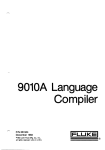
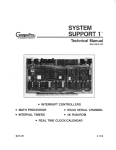
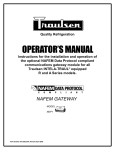
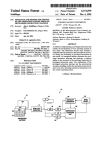
TechnicalData
Application Information B0157
Troubleshooting 8086/8088 Interrupt Circuitry
with the Fluke 9000-Series Troubleshooters
Introduction
This technical note illustrates how to test interrupt
vectors that are developed by an external interrupt where
the UUT microprocessor is either an Intel8 8086 or
Intel’ 8088. During normal operation, the microprocessor’s software preconditions the circuitry to accept
interrupts, establishes the vectors that correspond to a
particular interrupt and sets priorities. Upon receiving an
interrupt vector from a device the microprocessor
branches to a software routine to handle that particular
interrupt type.
When troubleshooting interrupt circuitry, it is important
to know if the microprocessor acknowledged and serviced
the interrupt that was generated. If not, the problem can
be diagnosed as either faulty hardware or software. The
philosophy of the 9000 Series is to test cicuitry in the
same manner that it operates, providing ability to test
interrupts in real-time closed-loop test situations.
To better illustrate the capabilities of the 9000 Series
Micro-System Troubleshooters when troubleshooting
interrupt circuitry, the IBM@ Personal Computer was
chosen as an example UUT. The microprocessor used is
the 8088 and the device that generates the interrupt
vector is an Intela 8259A Programmable Interrupt Controller (PIC). This technical note also illustrates the
immediate mode commands needed to test for interrupt
vectors when using the 8088/8086 pods. Included with
this technical note is a program listing for testing U2,
(the PIC) in the IBM PC.
How The 8088/8086 Microprocessors
Handle Interrupts
When an 808818086 microprocessor receives an interrupt
request, it will be acknowledged by executing two consecutive interrupt acknowledge bus cycles. The first
notifies the requesting device that the interrupt has been
acknowledged by the microprocessor. During the second
cycle, the PIC places eight-bits of data on the data bus
along with 3-bits of data on the CASO-CAS2 lines. The
eight-bit byte contains the interrupt vector type (O-255),
and the 3-bits of address information contains the cascade
address.
What Is An Interrupt Vector?
The interrupt vector is a code that will direct the
microprocessor to the proper service routine. The microprocessor contains an Interrupt Pointer Table that supports up to 256 interrupt types. The pointer table is the
link between the interrupt type code and the service
routine for that interrupt. The code in the pointer table
contains the address of the procedure that is to service
interrupts of that type. Interrupt type assignments may
be defined by programming the PIC with the microprocessor software. The steps and commands required to
program the PIC will be discussed later in this technical
note.
What Is A Cascade Address?
Each 82S9A is designed to service eight interrupts. With
the CASO-CAS2 lines, seven additional PICs may be
slaved together which would provide the capability of
servicing up to 64 interrupts. The CASO-CAS2 lines
form a private 8259A bus to control (similar to chip
select) a multiple 8259A structure. If the CASO-CAS2
lines are tied to the system address bus, the selection of
the slaved PICs becomes available as the Cascade Address.
Copyright i:~ 1983, John Fluke Mfg. Co., Inc. All rights reserved
How The 8088/8086 Pods Handle Interrupts
The 808818086 pods will handle interrupts in much the
same way as the microprocessor does during normal
UUT operation. The one exception is, the pod microprocessor will not jump to the interrupt routine to service
the interrupt that was generated. Instead the interrupt
type and the cascade address are stored in the pod for
further analysis by the operator or the Micro-System
Troubleshooter.
STATUS LINES
BIT
NUMBER
11
10
9
8
SIGNAL
MAXIMUM
MODE
INT VECT
‘R’G ERROR
TEST
MK’;.MX
PWR FAIL
3
2
1
0
MINIMUM
MODE
INT VECT
‘TESTMN &IX
PK’R FAIL
i- ‘ H O L D 1
’ ‘RESET
“RESET
-:-INTR
NM1
s-“HOLD0
t .READY
-;-INTR
NM1
f’ ‘HOLD
-I .READY
.; USER ENABLEABLE
FORCING LINES
Figure 1. Troubleshooter Display Message
Bit Assignments for the 8088.
As shown in figure 1, status bit 11 is identified as INT
VECT. When the interrupt type is recorded in the pod,
the INT VECT will be set high. At this time the pod has
a new interrupt vector available to be read. As long as the
INT VECT status bit is high, the interrupt acknowledge
routine is disabled. This means that interrupts will not be
serviced by the interrupt acknowledge routine until the
INT VECT status bit is reenabled. With the interrupts
disabled you can, however, force an interrupt acknowledge routine at any time with the use of a special address.
To reenable or force an interrupt acknowledge routine
requires the use of special addresses. The different special
addresses available for each pod are explained in detail in
the pod manual or the pod reference card. For the
purpose of this application note, a READ @ 500000 will
be defined as the address used to read the interrupt type
and reenable interrupts while a READ @ 600000 will
read the interrupt type without reenabling interrupts. A
READ @ 500002 will read the cascade address, and a
WRITE @ 500000 will force an interrupt acknowledge
routine at any time.
The operator also has the option of determining if
interrupts are to be disabled by using the Setup function
of the Micro-System Troubleshooter. The power-on default condition for the user-enabled Interrupt line is
“enabled.” If the operator wishes to disable interrupts he
simply answers “NO” to the setup question SETENABLE INTR?
In summary, to enable interrupts the following conditions
must be true: the INT VECT status bit is low and
through the setup commands, INTR ENABLE is set to
YES. To disable interrupts either of these conditions
must be true: the INT VECT status bit is high or
through the setup commands, INTR ENABLE is set to
NO.
With this information the necessary steps to handle
interrupts can be illustrated using the immediate mode
operation of the Micro-System Troubleshooter. To do this,
however, we must assume for the moment that the PIC
has been previously programmed to accept interrupts. To
generate interrupts for testing, set the probe to toggle in
the pulser mode of operation. The specifications of the
8259A require the interrupt input to remain at the device
until the first interrupt acknowledge bus cycle has occurred. The 8259A should see the first interrupt present
at its input and to avoid any potential timing problems
during the test we will synchronize the pulser to
FREE-RUN.
The following steps illustrate how the Micro-System
Troubleshooter and the 808818086 pod will handle
interrupts.
ENABLE
INTERRUPTS
READ @ 500000
By reading the interrupt
type, bit 11 in the status
register is set to a low which
reenables the interrupts.
GENERATE AN
INTERRUPT
Set pulser to toggle, sync to
free-run, place probe on
interrupt input.
MONITOR
STATUS BIT 11
READ STATUS
By performing this
operation the Micro-System
Troubleshooter will display
the condition of the bits in
the status register.
Observe the Micro-System Troubleshooter’s display. Is bit
11 a “l”? If so, an interrupt has been acknowledged and
we are now ready to read the interrupt type. If bit 11 is
still low this may be caused by a number of things such
as improper setup commands to the device, or a faulty
device.
READ INTERRUI’T TYPE
WITHOUT
REENABLING
INTERRUPTS
READ @ 600000
The Micro-System
Troubleshooter will now
display the Interrupt Type
that was saved in the pod
and won’t reenable the
interrupts.
3
Testing A Programmable Interrupt Controller
The previous immediate mode commands are the necessary steps for either the 8088 or 8086 pods to handle
interrupts. When actual testing of the interrupt circuitry
occurs there will be other Micro-System Troubleshooter
operations required which are UUT device dependent. In
most cases, when dealing with interrupt vectors the
device used is a Programmable Interrupt Controller
(PIC). The device dependent operations required are
command words which will setup the PIC in a known
configuration. The proper configuration must be determined prior to using your system and before the MicroSystem Troubleshooter can do any testing on the device.
Determining Proper PIC Initialization
The flow chart of the 8259A Initializationi , figure 2,
shows the necessary sequence of events for proper PIC
configuration.
c; Intel Corporation. Used with permission
Figure 2. Initialization Sequence
‘All information on the 8259A used in this application note can be
found in Intel’s iAI’X 86,88 User’s Manual, Application Note 59.
4
IFLUKEI
To set the bits in each command word properly, it is
necessary to understand how the PIC was designed into
the system as well as its expected operating characteristics. This can best be illustrated by the programming
format for Initialization Command Words (ICW).
To determine the proper command word it is necessary to
set each data bit to either a 1 or 0. Each word must be
constructed based on the desired operating characteristics
using the format found in the data sheet for the 8259A
illustrated in figure 3. The Micro-System Troubleshooter
only accepts data in hexadecimal form, so you must
convert the binary number to a hex number. For the
IBM PC the first ICW looks like this:
D7
D6
D5
D4
D3
D2 D1
DO
l0~0)0~1/0[0~1/1j
3
1
Using the same procedure as previously illustrated, the
following ICWs have been established for testing the PIC
in the IBM Personal Computer:
ICWl = 13H
ICW2 = OOH
ICW3 = not needed
ICW4 = OFH
The next piece of information that is needed to test the
PIC in the IBM PC is the address. The address for the
PIC is 20H, but the device is mapped into I/O space. To
have the Micro-System Troubleshooter “WRITE” to the
PIC the special I/O address must be used. The I/O
address space for the 8088 pod, as noted on the pod
decal, is in the range of 400000- 40FFFF. The complete
address for the device is 400020. Notice that when the
ICWl command was established, the A0 bit must be set
low. You must identify which address bit on your system
bus is tied to the A0 line for proper addressing. The IBM
PC has address bit 0 tied to the A0 line of the PIC. The
proper addresses for each of the ICW''s are as follows:
ICWl = address 400020 (A0 must be low)
ICW2 = address 400021 (A0 must be high)
ICW4 = address 400021 (A0 must be high)
F Intel Corporation. Used with permission.
Figure 3. Initialization Command Word Format
5
Initialization Procedure For The IBM PC
With the information that has been gathered to this point
we can now initialize the 8259A using the following three
Micro-System Troubleshooter commands:
WRITE @ 400020 = 13 SEND ICWl
COMMAND
SEND ICW2
WRITE @ 400021 = 0
COMMAND
SEND ICW4
WRITE @ 400021 = F
COMMAND
Once ICW4 has been sent, the PIC is ready to accept
interrupts at IRO-IR7. An IR input is an interrupt to the
PIC.
Before testing can begin one more command must be sent
to the device. In order to facilitate testing one interrupt at
a time the Operational Command Word 1 (OCWl command) will allow us to mask out any IR input. An OCW
allows further control of the PIC during operation. To
illustrate the testing of an IR input we will test the IRO
input. To determine the proper mask for the IRO input,
the following diagram is used. A “0” enables an IR input
and a “1” disables or masks the input.
D7
1
IR7
D6
D5
1
IR6
1
IR5
D4
1
IR4
D3
1
IR3
D2 Dl
1
IR2
1
IRl
DO
0
IRO
E
F
y-$iq
mi.8 Intel Corporation. Used with permission
The ICWl command established that interrupts would be
detected with edge triggering. With the probe synchronized to FREE-RUN, a steady stream of pulses (at a
1 kHz rate) will be available to generate interrupts. Place
the probe on the proper pin for the IRO input and toggle
the pulser (set the pulser to high and low). The pod
should now have an interrupt vector. To read the
interrupt vector type, perform the steps previously discussed on how to handle interrupt vectors.
In summary the commands that are required to test an
8259A for proper interrupt vector generation are listed
below:
Sync free-run
Send ICWl
Send ICW2
Send ICW4
Send OCWl
Enable interrupts
Generate an interrupt
Read status
Wait for INT VECT status bit to be high
Read the interrupt type
Interrupt Sync
An added feature of the 808818086 pods is the addition of
an interrupt sync mode for the Micro-System Troubleshooter. The interrupt sync mode is enabled by pressing
the SYNC button then 1. For oscilloscope operation, the
sync pulses leading edge will be at the first interrupt
acknowledge bus cycle and the trailing edge will be at the
end of the second interrupt acknowledge bus cycle
(remember the oscilloscope trigger is a differentiated
waveform). For probe operation, the sync pulse will
occur at the trailing edge of the second interrupt
acknowledge bus cycle. This sync mode is useful when it
becomes necessary to observe the timing of the interrupt
acknowledge to the PIC. It was mentioned previously
that one of the specifications of the 8259A is that the
interrupt to the PIC must remain at the IR input until
the device receives the first interrupt acknowledge. The
interrupt sync will help determine if this timing requirement is being met.
IBM Personal Computer Interrupt Vector Test
The objective of the test program for the 8259A (U2 in
the IBM PERSONAL COMPUTER) is to generate an
interrupt for each IR input and test if the proper
interrupt vector was placed on the bus. The program
tests U2 completely even if an improper vector is generated. If there is an improper vector, the Micro-System
Troubleshooter reports the error for approximately 7
seconds, increments an error counter and continues
testing the other IR inputs. When all eight inputs have
been tested a display message of “TEST COMPLETE”
will appear with the number of errors detected. After the
initial setup commands (for U2) the program will stay in
a loop monitoring bit 11 with the READ STS command.
If bit 11 is low (no interrupt vector) the Micro-System
Troubleshooter will display “INT VECT NOT AVAILABLE”. The only operator interface required will be that
the pulser is set to toggle and placement of the probe on
the proper pin when the display message appears. If an
error occurs the operator must keep track of that error
while testing is in process to know exactly which IR
input failed.
REGl = ERROR COUNTER
REG2 = DEVICE PIN COUNTER
REG3 = SET BIT FOR MASK
REG4 = EXPECTED VECTOR MASK
REGS = OCWl MASK
REG6 = SET DELAY TIME
IBM PERSONAL COMPUTER U2 INTERRUPT
VECTOR TEST
SYNC FREE-RUN
REGl = 0
REG2 = 12
REG3 = 1
REG4 = 0
WRITE @ 400020 = 13
WRITE @ 400021 = 0
WRITE @ 400021 = F
DPY-SET PULSER TO TOGGLE
DPY-+ PUSH CONT#
STOP
LABEL 1
REG5 = REG3 CPL AND FF
WRITE @ 400021 = REG5
READ @ 500000
DPY-PROBE U2 PIN @2
DPY- + PUSH CONT#
STOP
LABEL 5
READ @ STS
IF REG C AND 800 = 800 GOT0 2
DPY-INT VECT NOT AVAILABLE
GOT0 5
LABEL 2
READ @ 600000
IF REGE = REG4 GOT0 3
DPY-IR@ 4 ERROR WAS @ E not @ 4#
REG6 = 70
LABEL 4
DECR REG6
IF REG6 > 0 GOT0 4
INCR REGl
LABEL 3
INCR REG2
SHL REG3
INCR REG4
IF 1A > REG2 GOT0 1
DPY-TEST COMPLETE @ 1 IR ERRORS#