1
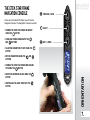
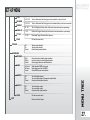
WARNING
ADHERE STRICTLY TO THESE AND ALL OTHER
SAFETY INSTRUCTIONS AND GUIDELINES!
1. The Eclipse Etek STAR Frame is not a toy.
2. Careless or improper use, including failure to follow
12. Treat every Etek STAR Frame equipped marker as if
3. Do not remove or deface any warnings attached to
at anything you do not intend to shoot.
4. Paintball industry standard eye/face/ear and head
protection designed specifically to stop paintballs and
meeting ASTM standard F1776 (USA) or CE standard
(Europe) must be worn by user and any person within
range.
5. Persons under 18 years of age must have adult
supervision when using or handling the Etek STAR
Frame.
6. Observe all local and national laws, regulations and
guidelines.
WARNING
to shoot.
instructions and warnings within this User Manual and
attached to the Etek STAR Frame could cause death or
serious injury.
the Etek STAR Frame.
.
11. Keep the Etek STAR Frame switched off until ready
7. Use only professional paintball fields where codes of
safety are strictly enforced.
8. Use compressed air/nitrogen only. Do not use CO2
9. Always follow instructions, warnings and guidelines
given with any first stage regulator you use with an Etek
STAR Frame equipped marker.
10. Use 0.68 calibre paintballs only.
it is loaded.
13. Never point the Etek STAR Frame equipped marker
14. Do not shoot at persons at close range.
15. Always measure your markers velocity before
playing paintball, using a suitable chronograph.
16. Never shoot at velocities in excess of 300 feet (91.44
meters) per second, or at velocities greater than local or
national laws allow
17. Do not fire the Etek STAR Frame equipped marker
without the bolt in the breech, as high-pressure gas will
be emitted.
18. Do not fire the Etek STAR Frame equipped marker
without the bolt pin locked securely in place.
19. Never look into the barrel or breech area of the Etek
STAR Frame equipped marker whilst the marker is
switched on and able to fire.
20. Never put your finger or any foreign objects into the
paintball feed tube of the Etek STAR Frame equipped
marker.
21. Never allow pressurised gas to come into contact
with any part of your body.
WARNING
ADHERE STRICTLY TO THESE AND ALL OTHER
SAFETY INSTRUCTIONS AND GUIDELINES!
22. Always fit a barrel-blocking device to the Etek STAR
23. Always remove all paintballs from the Etek STAR
Frame equipped marker when not in use on the field of
play.
24. Always remove the first stage regulator and relieve
all residual gas pressure from the Etek STAR Frame
equipped marker before disassembly.
25. The Etek STAR Frame euipped marker can hold a
small residual charge of gas, typically 2 shots, with the
first stage regulator removed. Always discharge the
marker in a safe direction to relieve this residual gas
pressure.
26. Always remove the first stage regulator and relieve
all residual gas pressure from the Etek STAR Frame
equipped marker for transport and storage.
27. Always follow guidelines given with your first stage
regulator for safe transportation and storage..
28. Always store the Etek STAR Frame equipped marker
in a secure place..
NOTE: this user manual must accompany the
product in the event of resale or new ownership.
should you be unsure at any stage you must seek
expert advice! (see service centers)
This Users Manual is in English.
It contains important safety guidelines
and Instructions. Should you be unsure
at any stage, or unable to understand the
contents within this manual you must seek
expert advice.
Le mode d’emploi est en Anglais.
I lcontient des instructions et mesures de
sécurité importantes. En cas de doute, ou
s’il vous est impossible de comprendre le
contenu du monde d’emploi, demandez
conseil à un expert.
ESTE MANUAL DE USUARIOS (oPERARIOS)
usarios está en Inglés.
Contiene importantes normas de
seguridad e instrucciones. Si no está
seguro de algùn punto o no entiende
los contenidos de este manual debe
consultar con un experto.
Diese Bedienungs - und
Benutzeranleitung ist in Englisch.
Sie enthålt wichtige Sicherheitsrichtlinen
und - bestimmungen. Solten Sie sich in
irgendeiner Weise un sicher sein. Oder
den inhalte dies heftes nicht versthen,
lassen Sie siche bitte von einen Experten
beraten.
WARNING
Frame equipped marker when not in use on the field of
play.
.
6Names
ORIENTATION
the component parts of the Etek STAR Frame.
This section is essential reading for everyone.
6 > KNOW YOUR Etek STAR Frame
7 > THE Etek STAR Frame NAVIGATION CONSOLE
8 INSTALLATION
8 > INSTALLING THE ETEK STAR FRAME ONTO AN ETEK and etek2 marker
14
QUICK SET-UP
Details on how to get up and running quickly with your
Etek STAR Frame. This section is essential reading for
everyone.
14
15
15
15
15
16
> INSTALLING A 9V BATTERY
> SWITCHING ON THE Etek STAR Frame
> SWITCHING OFF THE Etek STAR Frame
> FIRING The etek star frame
> the Etek STAR Frame circuit board
> USING THE BREAK-BEAM SENSOR SYSTEM
CONTENTS
17 USING YOUR Etek STAR
.
Frame
More detailed information on how to use and interact
with the Etek STAR Frame via its user interface.
17 > T-SLOT MOUNTING SYSTEM
17 > MACROLINE HOSING & ELBOWS
19 > SETTING THE TRIGGER
20 > USER INTERFACE
20 > SWITCHING ON
20 > RUN SCREEN LAYOUT
21 > UNDERSTANDING THE BBSS INDICATOR
22 > UNDERSTANDING THE LOCK INDICATOR
22 > UNDERSTANDING THE BATTERY INDICATOR
22 > THE GAME TIMER
22 > THE SHOT COUNTER
23 > THE AVERAGE RATE OF FIRE
23 > THE PEAK RATE OF FIRE
23 > THE MENU SYSTEM
24 MENU TREE
A quick reference guide to the user interface.
24 > MAIN MENU
24 > SET-UP MENU
28
ADVANCED SET-UP
In depth information on setting up the Etek STAR
Frame.
28 > ACCESSING THE MENU SYSTEM
28 > MOVING AROUNG THE MENUS
28 > ALTERING PARAMETERS
29 > THE MAIN MENU
29 > THE DISPLAY PARAMETER (display)
30 > THE GAME TIMER MENU (timer)
30 > GAME PARAMETER (game)
31 > ALARM PARAMETER (alarm)
31 > START PARAMETER (start)
32 > The Set-Up Menu
33 > THE TOURNAMENT LOCK PRESET PARAMETER (LOCK)
33 > THE PRESET MENU (preset)
33 > THE LOAD PRESET PARAMETER (load)
34 > THE SAVE PRESET PARAMETER (save)
34 > THE FIRING MODE PARAMETER (mode)
50 SERVICE CenterS
Information on the location of your nearest Etek STAR
Frame Service Center.
52 PARTS LIST
54 accessories
CONTENTS
35 > Rate of Fire Cap PARAMETER (rof cap)
35 > Maximum Rate Of Fire PARAMETER (max rof)
36 > RATE OF FIRE WITH BBSS OFF PARAMETER
(off rof)
36 > THE RAMP SETtings MENU (rmp set)
37 > THE RAMP TYPE parameter (type)
37 > THE LINEAR RAMP RATE PARAMETER (rate)
38 > THE RAMP START PARAMETER (pull no)
38 > THE RAMP KICK-IN PARAMETER (kick in )
39 > THE SUSTAIN RATE PARAMETER (sustain)
39 > THE RAMP RESTART parameter (restart)
40 > THE TIMING MENU
40 > THE Dwell parameter (dwell)
40 > the First Shot Drop Off compensation parameter (fsdo)
41 > the LIGHT parameter (light)
41 > the SLEEP parameter (sleep)
42 > The Filter Menu
43 > THE DEBOUNCE parameter (dbounce)
43 > THE EMPTy breech time parameter (empty)
44 > the Ball parameter (ball)
44 > the Pull PARAMETER (pull)
45 > the Release PARAMETER (release)
45 > THE BAND HIgh PARAMETER (band hi)
46 > THE BAND LO PARAMETER (band lo)
46 > BASIC TRIGGER FILTER SET- UP
46 > ADVANCED TRIGGER FILTER SET-UP
47 > THE TRAINING PARAMETER (trainin)
48 > THE HARDWARE menu
48 > THE TRIGGER PARAMETER (trigger)
48 > THE BBSS PARAMETER (bbss)
48 > THE AUX OUT PARAMETER (aux out)
.
KNOW YOUR Etek STAR Frame
A
B
H
C
D
G
ORIENTATION
E
.
I
ETEK STAR FRAME
ETEK STAR FRAME circuit BOARD
FRAME SCREWS FOR MOUNTING ETEK STAR FRAME ONTO AN ETEK2
FRAME SCREWS FOR MOUNTING ETEK STAR FRAME ONTO AN ETEK
T-SLOT / DOVETAIL ADAPTOR
ETEK QEV
LOW PRESSURE HOSE
RUBBER GRIP
RUBBER GRIP SCREWS
F
A
B
C
D
E
F
G
H
I
THE Etek STAR Frame
NAVIGATION CONSOLE
PREVIOUS / RAISE
At the rear of the Etek STAR Frame you will find the
Navigation Console. The Navigation Console is used for:
SELECT
> Turning the Etek STAR Frame on and off
using the
button
> Scrolling through MENUS WITH THE
and
buttons
NEXT / LOWER
> Selecting parameters to edit using the
button
> Editing parameters using the
buttons
and
> Resetting RECORDED VALUES using the
button
> CONTROLLING THE GAME TIMER WITH THE
BUTTON
ORIENTATION
> Turning the Etek STAR Frame BBSS on and
off using the
button
.
INSTALLING THE ETEK STAR
FRAME ONTO AN ETEK and an
etek2 marker
The Etek STAR frame can only be fitted to either an
Etek or Etek2 Paintball marker. The following installation
guide can be applied to either marker, but if you have
any doubts regarding fitting the Etek STAR Frame to
your Etek/Etek2 marker then you should contact your
nearest Eclipse Service Centre for advice. Full details of
Eclipse Service Centres can be found on pages 50 and
51 of this manual.
INSTALLATION
De-gas your marker and discharge any stored gas in a
safe direction before proceeding. Remove the loader,
barrel and air tank so that you can comfortably work on
the marker. Disconnect the 1/4” Macroline hosing from
both the elbow attached to the Inline Regulator and the
elbow attached to the OOPS at the base of your existing
grip frame. Remove the Inline Regulator by unscrewing
it from the front regulator mount (FRM) and the marker
should now resemble figure 1.1. Using a 5/64” hex key
remove the three countersunk screws from the right
hand side of the rubber grip (see figure 1.2) and peel
back the rubber grip to reveal the inside of the grip
frame (see figure 1.3).
.
FIG 1.1
FIG 1.2
FIG 1.3
Unplug the solenoid from its connector on the circuit
board, unplug the Break Beam Sensor System (BBSS)
from its connector on the circuit board (see figure 1.4).
Using a 1/8” hex key undo and remove both frame
screws by turning them in a counter-clockwise direction
(see figure 1.5). At this stage your existing frame can
now be removed from the marker body and set aside
for later use, leaving the marker body with the solenoid
assembly still attached as shown in figure 1.6 on the
next page.
FIG 1.4
FIG 1.5
INSTALLATION continued..
Using a 1/4” (1.2x6.5mm) sized flat-head screw driver,
unscrew the two banjo barb fittings from the rear of the
underside of your Etek or Etek2 body as shown in figure
1.7. Using a pair of snips, cut the low pressure hosing
from the barb on the Front Regulator Mount (FRM) so
that the solenoid assembly can be removed completely
from the marker body (see figure 1.8).
Cut the low pressure hose free from the two banjo barb
fittings on the body and the three barbs on the solenoid
minifold and discard, leaving the solenoid and minifold
assembly and two banjo barbs (see figure 1.9).
FIG 1.7
SUPER IMPORTANT NOTE: IF YOU ARE NOT FITTING THE
ETEK QEV, USE THE HOSE LENGTH TEMPLATE AT THE
BOTTOM OF PAGE 53
FIG 1.8
FIG 1.6
FIG 1.9
FIG 1.10
INSTALLATION
Referring to the hose length template at the top of page
53 of this manual, take the coil of low pressure hosing
that is included in your Etek STAR frame kit and cut the
three lengths of hosing that are required (see figure 1.10)
.
INSTALLATION continued..
Using a flat head screwdriver, screw the Etek QEV into
the rear fitting hole of the Etek/Etek2 body and screw
one of the banjo barb fittings into the front fitting hole of
the Etek/Etek2 body (see figure 1.11). Taking the longest
length of low pressure hose, attach one end to the barb
fitting on the FRM and the other to the barb labelled “1”
on the minifold; the solitary front barb (see figure 1.12). At
the other end of the minifold there are two barb fittings
that are labelled “2” and “4” on the minifold. Attach the
shortest length of low pressure hose to the barb labelled
“4” on the minifold, and attach the remaining length
of low pressure hose to the barb labelled “2” on the
minifold (see figure 1.13). Using a pair of non serrated
needle-nosed pliers attach the shortest hose to the
banjo barb fitting and the medium length of hose to the
barb fitting on the Etek QEV (see figure 1.14). Position
the solenoid assembly in the designated area on the
underside of the Etek/Etek2 body in preparation for the
frame to be fitted (see figure 1.15)
FIG 1.11
FIG 1.12
INSTALLATION
NOTE: Push all low pressure hose connections firmly
onto the barb fitting to ensure an adequate seal.
Replace as necessary if the low pressure hose is
damaged or stretched.
10.
FIG 1.13
FIG 1.14
FIG 1.15
INSTALLATION continued..
IMPORTANT: ENSURE BBSS WIRES ARE LINED UP WITH
THE DESIGNATED SLOTS IN THE FRAME PRIOR TO
ATTACHING FRAME TO MARKER BODY.
Carefully thread the solenoid and BBSS wiring
harnesses through the space in the top of the Etek STAR
Frame (see figure 1.16). Line up the Etek STAR Frame
so that it can be attached to the marker body, taking
care not to trap any of the wiring harnesses. Refer to
the diagram on page 52 of this manual and select the
correct sized frame screws (dependant on whether you
are fitting the frame to an Etek or Etek2 marker) and
using a 1/8” hex key attach the Etek STAR Frame to the
marker body (see figure 1.17).
FIG 1.16
NOTE: ALWAYS use the 3/8” length frame screw in the
Continue the installation process by plugging the
BBSS and solenoid wiring harnesses into their relevant
connectors on the Etek STAR Frame Circuit board (see
page 15), bending the wires as shown to ensure that
they do not obstruct the use of the Opto sensor or
micro-switch (see figure 1.18). Fit a 9 volt alkaline battery
(type PP3, 6LR61, MN1064) into the recess with the
battery terminals away from you. The positive terminal
(+) should be on the right hand side, nearest to the side
of the frame (See figure 1.19). Fit the rubber grip onto
the frame and using a 5/64” hex key attach the six
countersunk screws that hold the rubber grip onto the
grip frame (see figure 1.20 on the next page).
NOTE: The Etek STAR Frame utilizes a T-Slot mounting
rail as standard. If your chosen ASA Adapter uses
a dovetail, then you will need to install the dovetail
conversion rail included in the Etek STAR Frame kit.
FIG 1.17
FIG 1.18
FIG 1.19
INSTALLATION
front screw hole when attaching the Etek STAR Frame to an
Etek or Etek2 marker. The length of the rear frame screw will
vary according to which marker you are installing the frame
to. Please refer to page 52 of this manual, but if you are still
unsure please contact your nearest Eclipse Service Centre.
11.
INSTALLATION continued..
If installing the Etek STAR Frame onto an Etek2, take
the original Etek2 grip frame and use a 3/32” hex key to
loosen the two set screws that attach the OOPS body
to the bottom of the grip frame and remove the OOPS
from the base of the original Etek2 grip frame (see figure
1.21). The base of the Etek STAR Frame is compatible
with the T-Slot mounting system used on the Etek2 (see
figure 1.22) so taking your Etek2 OOPS slide it onto the
base of the Etek STAR Frame and using a 3/32” hex key
tighten the two set screws to lock the OOPS in place
(see figure 1.23).
INSTALLATION
If installing the Etek STAR Frame onto an Etek that does
not have a T-Slot mounted OOPS, use a 3/32” hex key
to loosen the set screw inside the original Etek grip
frame that tightens the OOPS body onto the base of
the grip frame so that it can be removed from the rail by
sliding it backwards (see figure 1.24). Slide the dovetail
conversion rail onto the bottom of Etek STAR Frame
and using a 3/32” hex key tighten the two set screws to
secure it in place (see figure 1.25 on the next page). Slide
the chosen ASA adaptor onto the dovetail conversion
rail and using a 3/32” hex key tighten the two set
screws that secure the ASA adaptor onto the dovetail
conversion rail (see figure 1.26 on the next page).
12.
FIG 1.20
FIG 1.22
FIG 1.21
FIG 1.23
FIG 1.24
INSTALLATION continued..
Complete the installation by screwing the Inline
Regulator back into the FRM (see figure 1.27) and reattach the length of 1/4” Macroline to the fitting in both
the Inline Regulator and the OOPS body (see figurE
1.28).
NOTE: If you suspect that the Macroline hosing that you
are using is damaged, replace immediately.
You have now successfully installed the Etek STAR
Frame onto your Etek/Etek2 marker.
FIG 1.27
FIG 1.25
FIG 1.28
INSTALLATION
FIG 1.26
13.
INSTALLING A 9V BATTERY
Ensure that the Etek STAR Frame is switched off. Lay
the marker on a flat surface in front of you with the feed
tube furthest away and with the barrel pointing to the
right.
Use a 5/64” (2mm) hex key to remove the three
countersunk screws that hold the rubber grip onto the
frame. Peel the grip to the right to expose the circuit
board within the frame.
Remove any fitted battery by sliding your thumb or
finger into the recess below the battery and levering the
battery out of the frame (See Figure 2.1).
DO NOT pull on the top of the battery to remove it as this
can cause the battery terminals to bend and will result in
a poor electrical connection.
QUICK SET-UP
Fit a 9-volt alkaline battery (type PP3, 6LR61 or
MN1604) into the recess with the battery terminals away
from you. The positive terminal should be on the right
hand side, nearest to the side of the frame (See Figure
2.2).
14.
FIG 2.1
Ensure that all of the wires are within the recess of
the frame and away from the trigger microswitch and
opto sensors so as not to interfere with their operation
and replace the rubber grip and replace the three
countersunk screws.
DO NOT over-tighten the screws.
NOTE: battery voltage must not exceed 10 volts.
some 9 volt rechargeable batteries can exceed
this voltage if over charged. if in doubt do not
use rechargeable batteries.
FIG 2.2
Switching On the Etek
STAR Frame
Press and hold the
button (See Figure 3.1). After one
second the Etek STAR Frame logo will be displayed.
Release the
button and the Run Screen will be
displayed.
Switching Off the Etek
STAR Frame
Press and hold the button until the display shows
OFF? Release the
button and re-press it to turn off the
Etek STAR Frame. Alternatively when the display reads
OFF?, you can pull the trigger once to turn off the Etek
STAR Frame.
FIRING THE Etek STAR Frame
C
B
A
The Etek STAR Frame
Circuit Board
There are three sockets on the Etek STAR Frame
Circuit board two of which are occupied by the BBSS
Connector (A) and the Etek STAR Frame Solenoid (B).
The third socket on the board (C) is the Auxiliary socket
to which third party products such as loaders and RF
transmitters can be connected using the relevant wiring
harness or parts. (See Figure 3.2)
FIG 3.2
QUICK SET-UP
Pull the trigger to fire the Etek STAR Frame. The entire
firing sequence is controlled electronically by the Etek
STAR Frame circuit board, enabling any user to easily
achieve high rates of fire.
FIG 3.1
15.
Using the Break Beam
Sensor System
The Break Beam Sensor System is used to detect when
a paintball is ready to fire from an Etek STAR Frame
equipped marker. If no paintball is ready then the BBSS
will inhibit the marker from firing. This prevents the
Etek STAR Frame equipped marker from ‘chopping’
paintballs that are not fully loaded into the breech.
To switch off the Break-Beam Sensor System, press and
hold the button for 0.5 second (See Figure 3.3).
The break beam sensor system indicator on the top
left of the LCD will change from
(enabled) to
(disabled) .
QUICK SET-UP
To switch the Break-Beam Sensor System back on, press
and hold the
button for one second. The indicator will
change back to .
16.
When the Break-Beam Sensor System is enabled, the
indicator will change depending on whether the system
has detected a ball or not. When no ball has been
detected the indicator looks like this when a ball has
been detected the icon changes to look like this .
Additional features of the Etek STAR Frame’s BreakBeam Sensor System are covered in full on page 21 of
this user manual.
FIG 3.3
NOTE: WHEN THE Etek STAR Frame IS TURNED ON,
THE BREAK-BEAM SENSOR SYSTEM IS AUTOMATICALLY
ENABLED
The Etek STAR Frame utilises a T-slot arrangement to
mount the OOPS to the bottom of the frame. The T-slot
is an improvement over the dovetail mounting system
found on most paintball markers, and is much more able
to withstand the rigours of modern tournament paintball.
For backwards compatibility there are industry standard
mounting holes in the base of the frame for mounting
third party air source adaptors (ASAs).
Macroline Hosing and
Elbows
To aid the longevity of your macroline hosing, it is very
important to remove it from (and install it back into) the
fittings in the correct manner:
Pull back the collet section of the macroline fitting and
keep the collet depressed.
Pull the macroline hose out of the macroline fitting and
release the collet.
Before installing the macroline hose into the macroline
fitting ensure that the end has been trimmed correctly to
ensure a tight fit in the fitting.
T-SLOT MOUNT
WARNING
If you EVER remove the Macroline hose from
the fitting, ALWAYS check the condition of
your Macroline hosing and if it is worn or the
wrong length replace it immediately.
USING YOUR ETEK STAR FRAME
T-Slot Mounting System
17.
SETTING THE TRIGGER
USING YOUR ETEK STAR FRAME
The Etek STAR Frame provides the user with the
option to use either a Micro-Switch or an opto sensor
as the means for detecting trigger pulls. Before you
begin to adjust and set your trigger, you must first
select the method of trigger detection that you wish
to use by entering the Set-Up Menu and making your
selection from the Hardware Menu (see page 48).
18.
There are four adjustment points on the trigger – the
Front Stop Trigger Screw, the Rear Stop Trigger Screw,
the Magnet Return Strength Screw and the Micro Switch
Activation Screw.
As standard each Etek STAR Frame comes with a
factory set trigger travel of approximately 2mm in total
length; one millimeter of travel before the firing point
and one millimeter of travel after the firing point, and the
trigger detection method set to opto.
The Front Stop Trigger Screw is used to set the amount
of trigger travel prior to the marker firing. Turn this screw
clockwise to reduce the amount of travel. Do not turn
the screw too far or the trigger will be pushed past the
firing point and the marker will not work. Turn this screw
counter-clockwise to increase the amount of trigger
travel (See Figure 4.1).
FIG 4.1
The Rear Stop Trigger Screw is used to set the amount
of travel after the marker has fired. Turn this screw
clockwise to reduce the amount of travel. Do not turn
the screw too far or the trigger will be prevented from
reaching its firing point and the marker will not work.
Turn this screw counter-clockwise to increase the
amount of travel (See Figure 4.2).
FIG 4.2
SETTING THE TRIGGER CONT...
4.3).
The Micro Switch Activation Screw is used to adjust the
point in the trigger pull at which the micro-switch is
activated. Turn the screw clockwise to decrease the
amount of trigger travel to the activation point. Turn
the screw counter-clockwise to increase the amount of
trigger travel to the activation point (See Figure 4.4).
If you have selected SWITCH from the HARDWARE Menu
and are consequently using the micro-switch as the
method of trigger detection then check that the microswitch activates and de-activates fully on each trigger
pull and trigger release. If you have selected OPTO from
the HARDWARE Menu and are using the OPTO sensor as
the method of trigger detection, refer to setting the BAND
HI and BAND LO (see page 45-46) as it is crucial that the
trigger pull and trigger filters are set up together for the
trigger filtering to work correctly.
FIG 4.3
FIG 4.4
USING YOUR ETEK STAR FRAME
The Magnet Return Strength Screw is used to adjust the
amount of force with which the trigger is returned to its
rest position by the magnet. Turn the screw clockwise to
increase the amount of force. Do not turn the screw too
far or it will negate the position of the Front Stop Trigger
Screw. Turn the screw counter-clockwise to reduce the
amount of force. Do not turn the screw too far or there
will not be enough force to return the trigger (See Figure
19.
USER INTERFACE
The Etek STAR Frame has a simple user interface
through which all aspects of it’s electronic control
system can be monitored and adjusted by means of the
three pushbuttons and graphical LCD which comprise
the Navigation Console.
USING YOUR ETEK STAR FRAME
SWITCHING ON
20.
Pressing and holding the
button will switch the Etek
STAR Frame on. The LCD display will show the Etek
STAR Frame logo. When the
button is released,
the LCD will show the Run Screen, which is the screen
displayed during the normal use of the Etek STAR
Frame.
RUN SCREEN LAYOUT
The root of the user interface is the Run Screen. This
screen is the one most often displayed and provides
the user with essential feedback on the state of the Etek
STAR Frame. A typical Run Screen is shown on the right.
On the right of the screen is a display option that is
user selectable from the Main Menu (see page 27). This
option can be:-
> a Game Timer
> a Shot Counter
> an Average Rate of Fire Indicator
> a Peak Rate of Fire Indicator
On the left of the screen is the current firing mode and
icons that provide graphical indication on different parts
of the Etek STAR Frame control electronics.
break-beam sensor
system indicator
USER SELECTABLE DISPLAY
OPTION
battery level
indicator / lock indicator
Understanding The BBSS
INDICATOR (BBSS)
The BBSS Indicator on the main screen is used to
indicate the eight possible states of the BBSS as
follows:
BBSS enabled and ball detected
The Etek STAR Frame can be fired at the
maximum rate of fire determined by the
chosen firing mode.
BBSS Enabled No Ball Detected
The Etek STAR Frame cannot be fired.
BBSS Disabled
The Etek STAR Frame can be fired at a
maximum rate of fire as set by the OFF ROF
parameter (see page 34)
BBSS Fault Detected
The system is disabled. The Etek STAR
Frame can only be fired at a maximum rate
of fire of 10bps, regardless of the chosen
firing mode.
BBSS Sensor Fault Has Been Cleared
The sensor has been re-enabled. A ball is
detected and the Etek STAR Frame can be
fired at the maximum rate of fire determined
by the chosen firing mode.
BBSS Fault Has Been Cleared
The sensor is enabled. No ball is detected
so the Etek STAR Frame cannot be fired.
To reset the BBSS icon, use the button
to switch off the BBSS and then back on
again.
BBSS ENABLED In Training Mode
The BBSS has been over-ridden as the
user has selected training mode. As the
user has chosen to leave the BBSS on, the
achievable rate of fire is limited by the firing
mode.
BBSS DISABLED In Training Mode
The BBSS has been over-ridden as the
user has selected training mode. As the
user has chosen to turn the BBSS off, the
achievable rate of fire is limited by the OFF
ROF parameter (see page 34).
USING YOUR ETEK STAR FRAME
The BBSS is able to switch itself off in the event that a
blockage or contamination prevents it from functioning
correctly. In this instance, the BBSS will switch itself
back on once the blockage is cleared and the correct
operation can be resumed.
21.
UNDERSTANDING THE LOCK
INDICATOR
USING YOUR ETEK STAR FRAME
The Etek STAR Frame has a tournament lock which
prevents the user from making changes to any
parameter that affects the way in which the Etek STAR
Frame shoots, without the need for tools. This feature is
necessary in order to make the Etek STAR Frame legal
for tournament play.
22.
When the lock is disabled, an open padlock
alternate with the battery indicator.
will
UNDERSTANDING THE
BATTERY LEVEL INDICATOR
The battery level indicator is used to show the state
of the battery within the Etek STAR Frame. When the
battery is fresh the indicator will show a ‘full’ battery
and as the battery is drained, so the indicator will show
the battery emptying. When the battery reaches a point
at which the Etek STAR Frame will no longer function
reliably, the indicator will start to flash. At this point the
battery must be changed immediately.
THE GAME TIMER
When the Game Timer is shown on the Run Screen
then it can be started by pressing the button and the
timer will start to count down. The Game Timer can also
be configured to start on a trigger press with the START
parameter (see page 31).
When the Game Timer reaches the ALARM time the
Gamer Timer will start to flash and the audible alarm will
sound every second, provided that the optional Eclipse
expansion board is fitted and the BEEPER parameter is
set to ‘on’.
When the Game Timer reaches 00:00, GAME OVER
will be displayed and the audible alarm will sound
continually, provided that the optional Eclipse expansion
board is fitted and the BEEPER parameter is set to ‘on’.
To stop the Game Timer at any time press and hold
the
button for 0.5 seconds.
To reset the Game Timer to it’s preset start time, push
and hold the button for 1 second. The Game Timer
will also be reset whenever the Etek STAR Frame is
switched off.
THE SHOT COUNTER
The Shot Counter increments every time that the Etek
STAR Frame is fired, regardless of whether the Shot
Counter is displayed or not. When the Shot Counter
is displayed on the Run Screen it can be reset to 0 by
pressing and holding the button for 0.5 seconds.
THE MENU SYSTEM
When the Average ROF is selected for display
the Run Screen will look something like the
screen to the right. The value displayed in the
top right of the screen represents the number
of full cycles completed in the last second
- the average rate of fire over the second. The
number below it is the maximum average rate
of fire that has been recorded. To reset this
maximum, press and hold the button for
0.5 seconds.
Behind the Run Screen is a structured menu system
comprised of multiple levels of menus. Each menu
contains a number of menu items and each menu
item can either be an editable parameter or a branch
to another menu. Branches always have an animated
graphic whereas parameters indicate their
current value.
TYPICAL BRANCH
TYPICAL PARAMETER
THE PEAK RATE OF FIRE
When the Peak ROF is selected
for display the Run Screen will look
something like the screen to the left,
which differs from the display of the
Average ROF by the inclusion of the
indicator ‘PK’. The value displayed in
the top right of the screen represents
the rate of fire measured between the
last two shots. The number below it is
the maximum peak rate of fire that has
been recorded. To reset this maximum,
press and hold the button for
0.5seconds.
The Peak ROF is typically higher than
the Average ROF as it is much easier to
fire two shots in quick succession than
it is to maintain a string over a longer
period of time.
The menu structure is shown in the following pages.
The menus are ‘smart menus’ in that they will expand
and contract depending upon the state of certain
parameters. For example, the MAX ROF parameter is
only visible when the ROF CAP parameter is set to ‘on’.
Smart menu items are indicated with a * in the table
below.
USING YOUR ETEK STAR FRAME
the average rate of fire
23.
MAIN MENU
MAIN MENU
OFF?
DISPLAY
TIMER
GAME
ALARM
START
BACK
MENU TREE
EXIT
24.
Turn off the Etek STAR Frame
Timer
Shots
Avg ROF
Peak ROF
Cancel
Display the game timer on the Run Screen
Display the shot counter on the Run Screen
Display the average rate of fire on the Run Screen
Display the peak rate of fire on the Run Screen
Cancel the display selection
00:00 - 60:00 Countdown game timer start time
00:00 - 10:00 Alarm activation time
Button
Trigger
Cancel
button starts the game timer
Trigger pull starts the game timer
Cancel game timer start event selection
Go back one menu level
Return to the Run Screen
SET-UP MENU
SET-UP MENU
LOCK
Off
On
Cancel
Turn the tournament lock off
Turn the tournament lock on
Make no changes to the tournament lock
LOAD
User 1
User 2
Factory
NPPL
PSP
MILLEN
CFOA
Cancel
Load the User 1 settings
Load the User 2 settings
Load the default factory settings (semi-automatic)
Load NPPL compliant settings
Load PSP compliant settings
Load Millenium Series compliant settings
Load CFOA compliant settings
Cancel the load operation
SAVE
User 1
User 2
Cancel
Save the current settings at the User 1 settings
Save the current settings as the User 2 settings
Cancel the save operation
PRESET
BACK
ROF CAP
MAX ROF*
OFF ROF
RAMP SET*
Go back one menu level
Semi
Ramp
Cancel
Select semi-automatic mode of fire
Select ramping mode of fire
Cancel the mode selection
Off
On
Cancel
Turn off the rate of fire cap
Turn on the rate of fire cap
Cancel the ROF cap selection
10.0 - 30.0
Rate of fire cap in balls per second when BBSS is enabled
4.0 - 15.0
Rate of fire cap in balls per second when BBSS is disabled
MENU TREE
MODE
25.
SET-UP MENU
TYPE
RATE*
PULL NO
KICK IN
SUSTAIN
RESTART
Step
Linear
Cancel
Select step type ramping
Select linear type ramping
Cancel the ramp type selection
0 - 100
Percentage linear ramp rate
4-9
Number of shots before ramping can start
5.0 - 15.0
Rate at which trigger has to be pulled in pulls per second before ramping can start
5.0 - 15.0
Rate at which trigger has to be pulled in pulls per second in order to maintain
ramping
0.0 - 1.0
Time in seconds after last trigger pull during which ramp can be restarted
Go back one menu level
BACK
TIMING
DWELL
FSDO
LIGHT
SLEEP
0.0 - 25.0
Solenoid energise time in milliseconds for each shot
0.0 - 3.0
First shot drop-off compensation time in milliseconds
0.0 - 20.0
Backlight off delay in seconds
0 - 60
Auto power off time in minutes
BACK
MENU TREE
FILTER
26.
DBOUNCE
EMPTY
BALL
Go back one menu level
TT
Level 9
.
.
Level 1
Cancel
Use Trigger Transition Filter
Use trigger debounce level 9 (less bounce)
1.0 - 20.0
Time in milliseconds that the breech must remain empty before the BBSS can look
for a paintball.
1.0 - 20.0
Time in milliseconds that a paintball must be in the breech for the Etek STAR Frame
to be ready to fire
Use trigger debounce level 1 (more bounce)
Cancel debounce selection
SET-up menu
RELEASE
BAND HI*
BAND LO*
TT TOL*
3.0 - 25.0
Time in milliseconds that the trigger must be pulled for a shot to be fired
3.0 - 25.0
Time in milliseconds that the trigger must be released before a pull can be recorded
51 - 99
Top limit (trigger activation point) of debounce band expressed as a percentage
1 - 49
Bottom limit (trigger release point) of debounce band expressed as a percentage
0 - 100
Percentage Trigger Transition Filter tolerance
BACK
TRAININ
HARDWARE
TRIGGER
BBSS
BEEPER
SIG OUT
BACK
EXIT
Go back one menu level
Off
On
Cancel
Training mode disabled
Training mode enabled
Cancel training mode selection
Opto
Switch
Cancel
Use opto sensor to detect trigger operation
Use micro-switch to detect trigger operation
Cancel trigger detection method selection
Lo Power
Hi Power
Cancel
Select standard BBSS power level
Select high power level for BBSS
Cancel BBSS power level selection
Off
On
Cancel
Turn off audible indicator
Turn on audible indicator (if expansion board fitted)
Cancel audible indicator selection
Off
On
Cancel
Turn off auxiliary output
Turn on auxiliary output
Cancel auxiliary output selection
Go back one menu level
Return to the Run Screen
MENU TREE
PULL
27.
ACCESSING THE MENU
SYSTEM
To access the Main Menu from the Run Screen, push
and hold the button for 1 second. The first item on
the Main Menu will be displayed.
To access the Setup Menu from the Run Screen, push
and hold the internal button for 1 second. The first item
on the Setup Menu will then be displayed.
NOTE: If the tournament lock is set to ‘off’
then the Main Menu and Setup Menu are joined
together which means that they can be accessed
in either of the two ways above.
ADVANCED SET-UP
MOVING AROUND THE MENUS
28.
Press and release the button to display the next item
on the menu. When the last menu item is displayed,
pressing the button will display the first item.
Press and release the button to display the previous
item on the menu. When the first menu item is
displayed, pressing the button will display the last
item.
When the displayed menu item is a branch, as indicated
by an animation on the right of the screen, press the
button to move to another menu.
ALTERING PARAMETERS
When the displayed menu item is a parameter, as
indicated by a parameter value on the right of the
screen, pressing the button will activate the EDIT
mode which allows the parameter value to
be altered. When EDIT mode is active, edit
indicators appear on the left of the screen
as shown in the screen below.
EDIT INDICATORS
There are two types of parameter, numeric
parameters and choice parameters. A
numeric parameter has a value which is a
number whereas a choice parameter is one
that has a small number of distinct choices.
Altering parameter values is essentially the
same for both types of parameter.
To alter a numeric parameter, first activate the EDIT
mode. Press the button to increase the parameter
value one step at a time. Press and hold the button
to increase the parameter value rapidly. When the value
reaches it’s maximum it will revert to it’s minimum value.
Press the button to decrease the parameter value
one step at a time. Press and hold the button to
decrease the parameter value rapidly. When the value
reaches it’s minimum it will revert to it’s maximum value.
When the required parameter value it displayed press
the button to accept the value and end the EDIT
mode.
To alter a choice parameter, first activate the EDIT mode.
Press the button to display the next choice in the
list. When the last choice is displayed, pressing will
display the first choice in the list. Press the button
to display the previous choice in the list. When the first
choice is displayed, pressing the button will display
the last choice in the list. When the required choice is
displayed press the button to accept the choice and
end the EDIT mode. If the displayed choice is Cancel
then pressing the button will end the EDIT mode and
restore the parameter to the value that is was prior to
editing.
The main menu
The Main Menu comprises parameters that do not affect
the way in which the Etek STAR Frame shoots and
which therefore do not have to be tournament locked.
THE DISPLAY PARAMETER
(display)
This parameter is used to select the information that is
displayed on the right of the Run Screen. This parameter
has the following choices:-
> TIMER: The Game Timer is displayed on the Run Screen
> SHOTS: The Shot Counter is displayed on the Run
Screen
> AVG ROF: The Average Rate of Fire is displayed on the Run Screen
> PEAK ROF: The Peak Rate of Fire is displayed on the Run Screen
> CANCEL: Editing is cancelled and the parameter remains unchanged.
From the Run Screen push and hold the button.
Initially, the current Preset configuration will be displayed
and then after one 1 second OFF? will be displayed, the
first item on the Main Menu.
To turn off the Etek STAR Frame, select the OFF? branch
or pull the trigger while the OFF? branch is displayed.
To return to the Run Screen, select the EXIT branch.
NOTE: if the lock option is disabled further
options will be displayed in the main menu.
ADVANCED SET-UP
This parameter differs from most others in that once a
choice has been made then the EDIT mode it ended and
the display returns to the Run Screen.
29.
the game timer menU
(TIMER)
This menu is comprised of parameters that control the
operation of the Game Timer:
GAME PARAMETER (GAME)
This parameter is used to set the game time; the time
from which the game timer counts down to zero. This
parameter can be set between 00:00 and 60:00 minutes
in 10 second increments and the factory default is 07:10
(7 minutes 10 seconds).
ADVANCED SET-UP
When the game timer reaches 00:00, GAME OVER will be
displayed and the audible alarm will sound continually,
provided that the optional Eclipse expansion board is
fitted and the BEEPER parameter is set to ‘on’.
30.
Alarm parameter (ALARM)
START PARAMETER (START)
An alarm condition is generated whenever the game
timer counts down to a specific time set by the ALARM
parameter. This parameter can be set between 00:00
and 10:00 minutes in 10 second increments.
This parameter is used to select the event which will
cause the game timer to begin counting down. This
parameter has the following choices:
> BUTTON: Pressing the
button will start the game
timer
> TRIGGER: Pulling the trigger will start the game timer.
> CANCEL: Cancel editing and leave the parameter unchanged.
When the alarm condition is generated the game timer
will start to flash and the audible alarm will sound every
second, provided that the optional Eclipse Expansion
Board is fitted and the BEEPER parameter is set to ‘on’.
ADVANCED SET-UP
NOTE: The Etek STAR Frame HAS THE ABILITY TO
BE UPGRADED WITH AN AUDIBLE ALARM FEATURE BY
INSTALLING AN ECLIPSE EXPANSION BOARD
(SOLD SEPARATELY).
31.
THE SETUP MENU
This menu is the starting point for access to all of the
parameters that control the way that the Etek STAR
Frame operates. To access this menu, first turn on the
Etek STAR Frame and then remove the 3 screws holding
the right hand cheek of the rubber grips (see figure 5.1).
Peeling back the cheek will reveal a red SETUP button
on the circuit board (see figure 5.2) which should be
pushed and held for 1 second.
If the tournament lock (LOCK) is off then this menu is
joined to the end of the Main Menu and can therefore be
accessed without tools.
ADVANCED SET-UP
FIG 5.1
32.
FIG 5.2
The Etek STAR Frame has a tournament lock which
prevents the user from making changes to any
parameter that affects the way in which the Etek STAR
Frame shoots without the use of tools.
This parameter is used to set the state of the tournament
lock and has the following choices:-
> OFF: Turn off the tournament lock. The SETUP menu is added to the MAIN menu, making it easily accessible by
pressing and holding the button.
> ON: Turn on the tournament lock. The SETUP menu is
only accessible by removing the right hand cheek of
the rubber grips and then pressing and holding the red
SETUP button on the circuit board.
> CANCEL: Cancel selection and leave the parameter
unchanged.
THE PRESET MENU (PRESET)
In order to simplify the set up of the Etek STAR Frame
a number of Preset configurations are available for
selection. Choosing one of these presets will cause all
of the necessary parameters to be set in such a way
as to make the Etek STAR Frame comply with the rules
governing a particular paintball league. It is also possible
for the user to save up to two Preset configurations of
their own.
THE LOAD PRESET
PARAMETER (LOAD)
This parameter is used to load the required Preset
configuration and has the following choices. With the
exception of FACTORY each of the Presets changes only
those parameters that control the firing mode of the
Etek STAR Frame, leaving Filter, Timing and Hardware
parameters unchanged.
> FACTORy: Reset every parameter to the factory set
defaults. The Etek STAR Frame leaves the factory set in
this way and this is also described on the Run Screen
as SEMI.
> NPPl: Load a set of parameters that configures the
Etek STAR Frame to comply with the 2007 NPPL rules
governing firing modes.
> PSP: Load a set of parameters that configures the Etek
STAR Frame to comply with the 2007 PSP governing
firing modes.
> MILLEN: Load a set of parameters that configures the
Etek STAR Frame to comply with the 007 Millennium
Series rules governing firing modes.
> CFOA: Load a set of parameters that configures the Etek STAR Frame to comply with the 2007 CFOA rules
governing firing modes.
> CANCEL: Editing is cancelled and the parameter remains
unchanged.
ADVANCED SET-UP
THE TOURNAMENT LOCK
PARAMETER (LOCK)
33.
THE LOAD PRESET
parameter cont...
THE FIRING MODE PARAMETER
(MODE)
> USER 1: Load a set of custom firing mode parameters
This parameter is used to select the firing mode of the
Etek STAR Frame and has the following choices:
that have been previously saved by the user.
> USER 2: Load a second set of custom firing mode
parameters that have been previously saved by the user.
With the exception of FACTORY each of the Presets
changes only those parameters that control the firing
mode of the Etek STAR Frame, leaving Filter, Timing and
Hardware parameters unchanged.
THE SAVE PRESET
PARAMETER (SAVE)
> SEMi: This is the default and in this firing mode the Etek
STAR Frame will fire one shot for every trigger pull.
> RAMP: In this firing mode, the rate of fire is increased above the rate at which the trigger is pulled once certain criteria have been met. These criteria are set by the
parameters on the RAMP SET menu.
> CANCEL: Editing is cancelled and the parameter is
unchanged.
ADVANCED SET-UP
This parameter is used to save the current set
of parameters as a user defined custom Preset
configuration. This parameter has the following choices:-
34.
> USER 1: Save the current parameters as the Preset
‘USER 1’
> USER 2: Save the current parameters as the Preset
‘USER 2’
> CANCEL: Editing is cancelled and the parameter remains
unchanged.
Please Note: Certain modes may only be available
in certain countries and on certain models of the
Etek STAR Frame.
RATE OF FIRE CAP
PARAMETER (ROF CAP)
MAXimum rate of fire
PARAMETER (MAX ROF)
The Rate of Fire Cap parameter is used to specify
whether or not the Etek STAR Frame should have a
limited, or capped rate of fire. When the ROF CAP is
enabled, the maximum achievable rate of fire is set
by the MAX ROF parameter. Choices for the ROF CAP
parameter are:> OFF: Rate of Fire only limited by the loader.
> ON: Rate of Fire limited to the MAX ROF parameter
value.
> CANCEL: Cancel editing and leave the parameter
unchanged.
The Maximum Rate Of Fire parameter is used to set the
maximum achievable rate of fire from the Etek STAR
Frame. The value of this parameter can be adjusted
between 10.0 and 30.0 balls per second in 0.1bps
increments.
The MAXIMUM RATE OF FIRE parameter will only be
displayed if you have set the ROF CAP parameter to ‘on’.
If the ROF CAP is switched ON, then the MAX ROF
parameter will feature as an item in the SET-UP Menu. If
the ROF CAP is switched OFF, the MAX ROF parameter is
redundant and omitted from the SET-UP Menu.
ADVANCED SET-UP
35.
ADVANCED SET-UP
36.
RATE OF FIRE WHEN BBSS
OFF PARAMETER (OFF ROF)
the ramp settings menu
(rmp set)
The OFF ROF parameter is used to control how fast the
Etek STAR Frame cycles when the Break-Beam Sensor
System is disabled. This parameter can be set between
4.0 and 15.0 balls per second and should always be set
to the slowest speed of the loading system in use.
This menu is only available when ramping has been
selected with the MODE parameter and comprises a list
of parameters that control the way in which the Etek
STAR Frame ramps, as shown below:
THE RAMP TYPE PARAMETER
(TYPE)
THE LINEAR RAMP RATE
PARAMETER (RATE)
This parameter is used to select the ramping style and
has the following choices:> STEP: Step ramping will cause the Etek STAR Frame to
shoot in semi-automatic until a number of trigger pulls,
set by PULL NO, have been made at a minimum pull
rate, set by KICK IN. At this point the rate of fire will step
up to the maximum rate of fire as set by MAX ROF (or
the maximum loader speed if the rate of fire cap, ROF
CAP is off). Ramping is maintained as long as the user
continues to pull the trigger at a required rate set by
SUSTAIN.
The parameter is only available when Linear Ramping is
selected and is used to set the percentage increase in
rate of fire over rate of trigger pulls.
Frame to shoot in semi-automatic until a number of
trigger pulls, set by PULL NO, have been made at a
minimum pull rate, set by KICK IN. At this point the rate
of fire will equal the rate of trigger pulls increased by the
percentage specified by RATE up to a maximum rate
of fire as set by MAX ROF, if the rate of fire cap is off).
Ramping is maintained as long as the user continues to
pull the trigger at a required rate set by SUSTAIN.
> CANCEL: Editing is cancelled and no changes are made
to the parameter.
This parameter can be set between 0 and 100% in 10%
increments.
ADVANCED SET-UP
> LINEAR: Linear ramping will cause the Etek STAR
For example, if the user is pulling the trigger at a rate of
10 pulls per second and the RATE parameter is set to
50% then the rate of fire is 10 plus 50% extra which is
15 balls per second.
37.
THE RAMP START PARAMETER THE RAMP KICK-IN
(PULL NO)
PARAMETER (KICK IN)
ADVANCED SET-UP
The parameter sets the number of trigger pulls that are
required at the KICK IN rate before ramping will start.
The parameter can be set between 4 and 9 pulls in
increments of 1.
38.
This parameter sets the minimum rate at which the user
has to pull the trigger in order to start ramping. This
parameter can be set between 5.0 and 15.0 pulls per
second in 0.1 pulls per second increments.
THE RAMP RESTART
PARAMETER (RESTART)
Once the Etek STAR Frame is ramping the user has to
continue to pull the trigger at a minimum rate in order to
maintain the ramping. This parameter sets this rate and
can be between 5.0 and 15.0 pulls per second in 0.1
pulls per second increments.
The RESTART parameter defines the amount of time
after the last trigger pull during which the ramp can be
restarted with a single trigger pull. If a trigger pull occurs
after the RESTART time has expired, then the other ramp
start conditions have to be met before ramping will
restart. This parameter can be set between 0.0 and 1.0
seconds in 0.1 second increments.
ADVANCED SET-UP
the sustain rate
parameter (sustain)
39.
THE TIMING MENU
The parameters on the Timing menu all relate to the
timing of specific events.
The fIRST SHOT DROP-OFF
COMPENSATION PARAMETER
(fsdo)
ADVANCED SET-UP
First shot drop off is a reduction in velocity of the first
shot fired after an extended period of not firing and is
caused by the stiction between dynamic o-rings and
the surfaces that they are in contact with. In order to
compensate for FSDO this parameter can be set to add
extra time to the DWELL parameter for the first shot. This
parameter can be set between
0.0 and 3.0 milliseconds.
40.
THE DWELL parameter
(dwell)
The Dwell parameter sets the amount of time that the
solenoid is energized and therefore the amount of gas
that is released with each shot of the
Etek STAR Frame. Setting this parameter
too low will result in low velocity shots
and/or excessive shot to shot velocity
fluctuations. Setting the parameter too
high will simply waste gas and make the
Etek STAR Frame louder.
The DWELL can be set between 0.0 and
25.0 milliseconds. The factory default
setting can normally be reduced after
a few thousand shots as the marker
‘beds-in’.
The SLEEP parameter
(SLEEP)
The LCD backlight is illuminated whenever any of the
buttons are pressed on the Etek STAR Frame. The LIGHT
parameter is used to set the amount of time that the
backlight stays lit between 0.0 and 20.0 seconds in 0.5
second increments. Setting this parameter to 0.0 will
prevent the backlight from coming on when a button is
pressed.
If the Etek STAR Frame is inactive for a period of time
then it will automatically switch off in order to save
power. The SLEEP parameter is used to set that time
between 0 and 60 minutes in 5 minute increments.
Setting this parameter to 0.0 will prevent the Etek STAR
frame from automatically switching off.
ADVANCED SET-UP
THE LIGHT PARAMETER
(light)
41.
THE FILTER MENU
ADVANCED SET-UP
The parameters on the Filter menu are all used to tune
the Etek STAR Frame’s software filters which prevent the
Etek STAR Frame from firing unless all of the necessary
conditions are met. The factory default settings will be
suitable for most set-ups, however certain loader and
trigger set-ups may require modification of one or more
of these parameters.:
42.
THE DEBOUNCE parameter
(dbounce)
the Empty Breech time
parameteR (empty)
This parameter is used to combat any trigger bounce
that might occur in the Etek STAR Frame.
In order for the BBSS to function correctly it must first
detect that the bolt is fully retracted and the breech is
empty, and then detect that a paintball is loaded into the
breech before the Etek STAR Frame is allowed to fire.
Slots or holes in some third party bolts can fool the BBSS
and so this parameter is used to specify a minimum time
that the breech must be empty. The parameter can be
set between 1.0 and 20.0ms in 0.5ms increments.
ADVANCED SET-UP
This parameter can be set to the following choices:> TT: The Trigger Transition Filter is used to remove
trigger bounce.
> LEVEL 9: The debounce filter is used to remove trigger
bounce, this filter has nine levels with level 9 providing
the most filtering and
> LEVEL1: Level 1 providing the least filtering.
> CANCEL: Cancel editing and leave the parameter
unchanged.
43.
THE BALL parameter (Ball) THE PULL parameter (pull)
ADVANCED SET-UP
Tumbling paintballs can take time to settle in the breech
before they can be successfully fired. This parameter
is used to set the amount of time that a paintball has to
be in the breech before the Etek STAR Frame is allowed
to fire. This parameter can be set between 1.0 and 20.0
milliseconds in 0.5ms increments.
44.
The PULL parameter is used to set the minimum
amount of time that the trigger must be pulled before
it is recognised as a valid trigger pull. This parameter
can be set between 1.0 and 20.0 milliseconds in 0.5ms
increments.
the Band High parameter
(band hi)
The RELEASE parameter is used to set the minimum
amount of time that the trigger must be released
before it is recognised as a valid trigger release. This
parameter can be set between 3.0 and 25.0 ms in 0.1
ms increments.
The BAND HI parameter is only available if OPTO has
been selected in the HARDWARE menu. BAND HI defines
the point at which the trigger is considered pulled and is
adjustable between 51% and 99% in 1% increments.
ADVANCED SET-UP
THE release PARAMETER
(release)
45.
THE BAND LOW parameter
(band Lo)
BASIC TRIGGER FILTER
SET-UP
The BAND LO parameter is only available if OPTO has
been selected in the HARDWARE menu. BAND LO defines
the point at which the trigger is considered released and
is adjustable between 1% and 49% in 1% increments.
95% of trigger bounce problems can be eliminated by
utilizing one of the nine fixed DEBOUNCE choices (LEVEL
1-9). In attempting to eliminate trigger bounce it is
advisable to try the nine fixed DEBOUNCE choices before
attempting any advanced set up of the trigger filters.
ADVANCED TRIGGER FILTER
SET-UP
ADVANCED SET-UP
In order to optimize the Trigger Filters it is necessary to
have the BAND HI parameter set as high as possible and
the BAND LO parameter set as low as possible:
46.
1. Select the BAND HI parameter. Observe that the graphical
bar rises and falls as the trigger is pulled and released. The
actual value of the graphical bar is displayed in the top right of
the display.
2. Set the REAR STOP TRIGGER SCREW as required, ensuring
that the bar is as close to 100% as possible when the trigger
is fully depressed against the set screw. It is advisable to
allow for some extra travel in the trigger pull once the bar has
reached its maximum value.
3. Adjust the BAND HI parameter so that when the trigger is
fully depressed the bar settles above the indicator on the left
hand side of the screen (SEE PAGE 45).
4. Select the BAND LO parameter. Observe that the graphical
bar rises and falls as the trigger is pulled and released. The
actual value of the graphical bar is displayed in the top right of
the display.
5. Set the FRONT STOP TRIGGER SCREW as required, ensuring
that the bar is as close to 0% as possible when the trigger
is fully released against the set screw. It is advisable to allow
for some extra travel in the trigger release once the bar has
reached its minimum value.
6. Adjust the BAND LO parameter so that when the trigger is
fully released the bar settles beneath the indicator on the left
hand side of the screen (See PAGE 46).
THE TRAINING parameter
(trainin)
7. Set the MAGNET RETURN STRENGTH SCREW and the Micro
Switch Activation Screw as required, making both the spring
tension and the return force as strong as possible without
compromising the “feel” of the trigger.
The TRAININ parameter is used to select Training Mode.
In Training Mode the Etek STAR Frame will function
exactly the same as normal but with two important
differences:-
Optional (only if TT had been selected in Debounce
parameter):
1. The solenoid valve is under-driven so that the rammer
only moves a small amount and does not strike the
exhaust valve. This simulates the firing cycle without
wasting air and generating lots of noise.
Whilst this set up process should
completely eliminate bounce, it may result
in a trigger pull that is not ideally suited to
the user, in which case it will be necessary
to make adjustments to the trigger and
then modify the Trigger Filter parameters
accordingly.
note: The fastest way to shoot an Etek STAR
Frame is to walk the trigger with two or more
fingers. feathering (not fully releasing)
the trigger will cause the filtering system
to reduce the rate of fire down in order to
eliminate what it perceives as trigger bounce.
2. The BBSS is overridden so that the Etek STAR
Frame can cycle without paint. The centre of the BBSS
indicator changes to a ‘T’ to indicate that Training Mode
is enabled.
The Training parameter choices are as follows:-
> OFF: Training Mode is disabled and the Etek STAR
Frame functions normally.
> ON: Training Mode is enabled.
> CANCEL: Cancel editing and leave the parameter
unchanged.
ADVANCED SET-UP
8. Select the TT TOL parameter. With the gun gassed up
and preferably fitted with loader and firing paint, try to get
the marker to bounce by pulling the trigger very slowly. If
the marker bounces, then reduce the
TT TOL value until it no longer does so.
If the marker does not bounce then
increase the TT TOL value until it starts to
bounce and then reduce it again until the
bouncing stops.
47.
THE HARDWARE MENU
The HARDWARE Menu comprises parameters that
control low level functionality of the Etek STAR Frame
electronic hardware.
ADVANCED SET-UP
THE TRIGGER PARAMETER
(trigger)
48.
The Etek STAR Frame is fitted with a dual trigger pull
detection system. A non-contact opto-electronic trigger
sensor arrangement is used to detect trigger movement
whilst a micro-switch is used to provide a more
traditional tactile feedback for the trigger. The TRIGGER
parameter is used to select which system is used. The
choices available are as follows:-
> OPTO: Select the Opto sensor for trigger pull detection.
> SWITCH: Select the micro-switch for trigger pull
detection.
> CANCEL: Cancel editing and leave the parameter
unchanged.
THE BBSS PARAMETER (BBSS)
This parameter controls the amount of power used by
the Break Beam Sensor System and should normally be
left on it’s default low power setting. However scratches
on the surface of either of the sensors, or the use of
some third party sensors, may require that the BBSS
power level be increased. Higher power levels will cause
more drain on the battery. The choices available for this
parameter are:-
> LO POWER: Low power BBSS drive
> HI POWER: High power BBSS drive
> CANCEL: Cancel editing and leave the parameter unchanged
THE AUXiliary output
PARAMETER (AUX OUT)
The auxiliary output is on a three pin connector in
the circuit board and is used to provide an interface
between the Etek STAR Frame and third party
equipment such as loaders. The AUX OUT parameter
is used to enable the auxiliary output which pulses
every time the Etek STAR Frame is fired. The parameter
choices are:> OFF: Auxiliary output off.
> ON: Auxiliary output on.
> CANCEL: Cancel editing and leave the parameter
unchanged.
NOTE: If the optional Eclipse expansion board is fitted
then the output on that board is pulsed at the same time
as the auxiliary output.
49.
ECLIPSE CERTIFIED SERVICE CenterS
Are you unsure of where to send your Etek STAR Frame to be repaired or serviced? If your local Eclipse dealer
can’t assist you, why not contact your nearest Certified Eclipse Service Center and arrange to send it into them to
undertake any work that you require.
UNITED KINGDOM & EUROPE
PLANET ECLIPSE LTD
England
Call:
Fax:
Email:
Visit:
+44(0)161 872 5572
+44(0)161 872 5972
[email protected]
www.planeteclipse.com
ACTION PAINTBALL GAMEs
Russia
Call:
Fax:
SERVICE CENTERS
Email:
Visit:
50.
+7(0) 95 7851 762
+7(0) 95 7851 738
[email protected]
www.paintball.ru
Adrenalicia S.L.
Spain
Call: Fax: Email: Visit: ++34 669 011 515
++34 986 730 131
[email protected]
www.adrenalicia.com
TCB Paintball
Sweden
Call: Email: Visit: ++46 702 317 361
[email protected]
www.tcbpaintball.com
Coolgames
++49(0) 211 210 2300
++49(0) 211 210 23030
[email protected]
www.paintball.de
France
Call:
Fax:
Email:
Visit:
+33(0)1 41 09 1004
+33(0)1 41 09 1009
[email protected]
www.paintballcamp.com
Ponto de Mira
Portugal
Call: Fax: Email: Visit: ++351 214 120 144
++351 214 120 144
[email protected]
www.pontodemira.com
WestSport
Norway
Call: Email: Visit: ++358 9 586 5312
[email protected]
www.coolgames.fi
Hungary
Call: Email: Visit: Portugal
Call: Fax:
Email: Visit: ++351 213 863 637
++351 213 863 715
[email protected]
www.estratego.com
SKILL Paintball
CAMP
++47 4077 4418
[email protected]
www.westsport.no
Breakout KFT
Finland
Call: Email: Visit: EstratEgo Portugal
OPM
Germany
Call:
Fax:
Email:
Visit:
++36 203 563 604
[email protected]
www.joinpaintball.hu
Poland
Call: Fax: Email: Visit: AGS
++48 22 875 2777
++48 22 212 8018
[email protected]
www.skill.com.pl
Czech Republic
Call: ++420 272 762 938
Fax: ++420 272 762 938
Email: [email protected]
Visit: www.paintballshop.cz
Usa & canada
Rhode Island
Call: (401) 247 9061
Fax: (401) 247 0931
Email: [email protected]
Visit: www.planeteclipse.com
DGX Paintball
West Coast and California
Call: (707) 255 5166
Email: [email protected]
Visit: www.dgxpaintball.com
Paintball Showcase
East Coast
Call: Email: Visit: (401) 353 6040
[email protected]
www.paintballshowcase.com
Ground Zero Paintball
Southern States
Call: (888) 759 2578
Email:
[email protected]
Visit: www.gzpaintball.com
Extreme Skate and Paint
Paintball Central
Florida
Hawaii
Call: Email: Visit: (808) 533 0462
[email protected]
www.pbchawaii.com
Midwest
(402) 403 1880
[email protected]
www.proSTARpb.com
Maximum Paintball Sports
Texas
REST OF THE WORLD
Call: Email: Visit: (210) 659 0424
[email protected]
www.texasxfactor.com
Skirmish Paintball Asia
Action Paintball Games
Call: Fax: Email: Visit: Call: Fax: Email: Visit: Malaysia
++603 7722 5629
++603 7722 1435
[email protected]
www.skirmishpaintballasia.com
Extreme Indoor Paintball
Australia
Call: Email: Visit: Call: Email: Visit: (305) 248 3145
[email protected]
www.espxtremesportz.com
Badlands Paintball
Canada
Pro STAR Paintball
Call: Email: Visit: Fox Paintball
Call: (630) 585 5651
Email: [email protected]
Visit: www.foxpaintball.com
Call: Email: Visit: (416) 245 3856
[email protected]
www.badlandspaintball.com
Paintball Central
North Carolina
Call: (336) 458 0060 (ext. 14)
Fax: (336) 274 5655
Visit: www.paintballcentral.com
www.pbcsportspark.com
Australia
++61 2 9679 0011
++61 2 9679 0100
[email protected]
www.actionpaintball.com.au
The Paintball Shop
South Africa
++61 1 300 972468
Call: ++27 413640549
[email protected] Fax: ++27 413640549
www.extremeindoorpaintball.com.au
Email:
[email protected]
Visit: www.paintballshop.co.za
SERVICE CENTERS
Planet Eclipse LLC
51.
PARTS LIST
SCREW
52.
QTY
DESCRIPTION
7
PCB SCREW (3), BEARING CARRIER (2), QEV BLOCK (2)
8
RUBBER GRIP SCREW (6), BBSS COVERS SCREW (2)
1
MICROSWITCH SCREW
4
TRIGGER ADJUSTMENT SCREW
2
T-RAIL SCREW
2
10-32 UNF x 3/8” ETEK2 STANDARD FRAME SCREW
1
10-32 UNF x 1/2” ETEK STANDARD FRAME SCREW
1
10-32 UNF x 5/8” ETEK LONG FRAME SCREW
( M3 x 5 CAP HEAD SOCKET)
( 6-32UNC x 3/8 COUNTERSUNK SOCKET)
( 6-32 UNC x 1/2 SOCKET SET SCREW)
( 6-32 UNC x 3/16 SOCKET SET SCREW)
( 10-32 UNF x 1/2 SOCKET SET SCREW)
( FRONT FRAME SCREW (ETEK STAR FRAME))
( REAR FRAME SCREW WHEN FITTING AN ETEK STAR FRAME TO AN
ETEK2)
( REAR FRAME SCREW WHEN FITTING AN ETEK STAR FRAME TO AN ETEK)
Hose lengths (qev fitted)
DESCRIPTION
Smallest Piece:
Banjo fitting to left side rear barb on minifold.
medium piece:
QEV to right side rear barb on
minifold
longest piece:
Front barb on minifold to FRM
Hose lengths (no qev fitted) DESCRIPTION
medium piece:
Rear banjo fitting to right side rear barb on
minifold.
longest piece:
Front barb on minifold to FRM
PARTS LIST
Smallest Piece:
Front banjo fitting to left side rear barb on
minifold.
53.
TECH FLEX MAT
Protect your Ego whilst you maintain
it with the Eclipse Tech Flex Mat.
BALL DETENTS
ACCESSORIES
10 Replacement rubber Detents for
your Ego8.
54.
08 Stripe laptop bag
Transport your Laptop in style with
the new ‘08 Laptop Bag.
Eclipse Shaft 2 Barrel Kit
3 different bores size backs,
2 different length barrel tips; a
combination to suit every occasion.
08 Stripe kitbag
What better place to keep your
Ego8?
Laser Eye Kit
Add a Red Laser Beam to the breach
of your Ego8 or Etek marker with this
Laser Eye Kit! This product is not
compatible with other Egos.
The recommended oil to use on
all maintenance and servicing
procedures.
Eclipse Ego8/Etek Tool Tube
This handy little tool tube includes all
of the hex key sizes that you will need
to strip and maintain your Ego8 or
Etek marker.
ECLIPSE stars wristbands
BURN BEANIE
Won’t help you shoot any straighter,
Fed up of wearing gloves but can’t
won’t make you run any faster but
take the pain of getting shot on a
gloveless hand? Settle for the happy will make you look the part as you’re
medium of one of the new Eclipse Star strutting your stuff on-field. Keeps
your noggin nice and cosy too!
Wristbands then and save the pain!
Etek zick kit
Kick? What kick? Add the Etek ZICK Kit to your
Etek marker and the existing amount of kick will be
reduced even further. Include a replacement rammer
and rammer cap that must only be used together.
ACCESSORIES
ECLIPSE GUN OIL
55.
Etek, the Etek Icon, Ego and the Ego logo are all trademarks of Planet Eclipse Ltd. All artwork and texts © Copyright 2007-2008. STRFRMVOL1