1
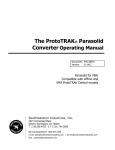
Installation Instructions
(110/220V Single phase Input using ABB ACS250 VFD)
1
TABLE OF CONTENTS
Parts List ………………………………………………….………... Page 3
Fan Placement, Spacing, and Clearance ………….……..….…. Page 4
Fan Maintenance ……………………………………………….…. Page 4
Installation Instructions ………………………….…………….….. Page 5
Fan Control Instructions …………………………………………. Page 16
2
MECHANICAL ITEMS INCLUDED IN YOUR SHIPMENT
5 Fan Blades
5 Fan Blade Flaps
5 Fan Blade End Caps
1 Fan Drive Assembly
1 Beam Mounting Bracket
3 ¼” Turnbuckles with jam nuts
Gearbox Vent (Must be installed)
Bolts, nuts, washers, and clamps of various sizes (see Installation Instructions for types and
quantities)
ELECTRICAL ITEMS INCLUDED IN YOUR SHIPMENT
1 Lockable disconnect with installation instructions
- 1 ABB ACS250 Variable Frequency Drive (VFD)
a. Three (3) wire crimps for motor control cable
b. One (1) ACS250 drive User’s Manual
c. 1 motor control cable (fan motor to VFD)
d. Two (2) motor cable strain reliefs
FAN SAFETY COMPONENTS PROVIDED
Drive Assembly safety cable (1)
Guy wires (3)
Blade Safety Brackets (5)
TOOLS TO GET STARTED
Scissor lift
Wrench and socket set (5/16”-3/4” needed)
Cordless power driver with clutch and Phillips Bit
1/4” Nut driver
Torque wrench
Standard and Phillips screwdrivers
Instrument screwdriver (1/8” flat blade)
Wire stripper/cutter
Level
3/16” “L” shaped Allen wrench
Three (3) beam clamps with eye bolts
Check that all necessary parts are included with your shipment. Should an item be missing,
contact Patterson immediately at (800) 768-3985.
3
Note: In order to protect personnel, equipment, and the fan, it is important that all safety
components are installed per these instructions. Failure to properly install any or all of these
safeguards may void the manufacturer’s warranty. Electrical installation should be
performed by a licensed electrician.
FAN SPACING, PLACEMENT, AND CLEARANCE
Fans should be mounted such that the blades are a minimum of 10 feet above the floor. The
ideal height is 20 to 25 feet. Also, ensure that the fan blades have a clearance equal to 15%
of the fan’s diameter in all directions.
Care should be taken when installing the fan around a fire sprinkler system. The VFD is
equipped with the ability to connect to a fire suppression system – stopping the fans in case
of a fire. However, it is the responsibility of the installer to read and comply with all local
codes and regulations.
MAINTENANCE
Prior to performing any maintenance on the fan, it MUST be disconnected from the power
source by means of the separate lockable disconnect provided.
VFD Box – Clean heat dissipating fins on the back of the box periodically.
Gearbox – Periodic maintenance will ensure your fan remains operational for its intended
life. While Patterson recommends the end-user check and change the gearbox oil annually,
failure to do so will not void any warranties. Oil type used is Chevron® Delo Gear ESI 85W140. Contact Patterson at (800) 768-3985 for availability.
Hub Grease – Hub should be inspected yearly to ensure proper lubrication. Grease type is
Chevron Delo HD Moly 5%. There are two grease fittings, an upper and lower. Add grease
as needed, filling each area slowly until grease passes through the upper seal.
Mounting Hardware – All nuts and bolts related to mounting of the fan unit should be
checked for tightness annually. In addition, guy wires need to be inspected to ensure they
remain taut and show no signs of fraying.
Blades – Blades can be occasionally wiped down with a damp cloth. A mild detergent can
also be used if desired.
4
INSTALLATION PROCEDURES
Step 1: Install VFD on wall or other structure
Reference: Page 17 of the ACS250 User’s Manual
A) Determine where to mount the fan’s VFD. It should be on a wall or other solid
structure, and at a height that is easily accessible for fan control. Be sure to leave
enough space around the VFD so that its heat dissipating fins can function properly.
B) Using the mounting holes provided, securely mount the VFD to the wall/structure
(hardware not provided).
Step 2: Attach Mounting Bracket to Structure
A) It is important to attach the mounting bracket to the structure first and then connect the
fan assembly.
B) Refer to Image 1 to determine which set of bolt slots to use:
Image 1
i)
ii)
For I-beam width less than 7¼”, use slots labeled “A”. I-beams wider
than 7¼” should use slots labeled “B”.
For I-beam thickness greater than ½”, use the provided spacer as shown
in Image 2.
5
Image 2
iii)
iv)
Attach clamp to structure, torqueing GRADE 8 ½” bolts to 80 ft-lbs.
(OPTIONAL) When attaching the mounting bracket to added “bridges”
between two or more points of an existing structure (i.e. bar joists, Zpurlins, etc.), orient the beam plate as shown in Image 3. This will ensure
guy wire cables are properly aligned with the structure. In this
configuration, the beam clamps will NOT be necessary. Also, longer
GRADE 8 ½” bolts are needed (not provided).
Image 3
v)
If a down rod was ordered, remove the 4¾” connector and replace with
the longer down rod. Refer to Image 2.
6
Step 3: Attach Fan Assembly to Mounting Hardware
A) Using a scissor lift, raise the fan assembly and guide the connector (or down rod) into
the tube on top of the fan frame until its mounting holes line up (see Image 4).
Image 4
Image 5
B) Secure the fan to the swivel assembly (or end of down rod) as shown in Image 5.
Torque bolts to 35 ft-lbs.
Step 4: Install Fan Assembly Safety Cable
Note: This step is required. Failure to install the safety cable may void the
manufacturer’s warranty.
A) Pass one end of the safety cable underneath where the three vertical frame members
join together (at the top of the fan drive assembly).
B) The opposite end of the safety cable should be passed over the top of the I-beam or
other mounting structure. Connect the two ends of the cable together by means of 3
saddle clamps (provided) in the manner shown in Image 7.
C) Tighten the saddle clamps securely using a ½” socket. Torque to 15 ft-lbs
7
Image 7
Step 5: Connect Motor Control Cable to Fan Motor
A) Remove the cover of the motor junction box, and then remove one of the junction box
knockouts.
B) Pass the cable conductors and shielding through one of the provided strain reliefs, and
then through the knockout hole in the junction box.
C) Connect the end of the motor control cable to the fan motor. The wiring
configuration is input voltage dependent. Please wire the motor for a 220V input
using the wiring diagram found on the fan motor’s nameplate. This 220V wiring
configuration also applies if the power source is 110V single phase.
D) Once cable is properly connected inside the junction box, tighten the strain relief.
Replace junction box cover.
E) Run the rest of the motor control cable down near the wall mounted VFD. Using
conduit for this run is recommended.
8
Step 6: Install Lockable Disconnect/ Run Input Power to Drive/Connect
Motor Control Cable to Drive
References: Page 9 and Chapter 5 of the ACS250 User’s Manual
Lockable Disconnect Installation Instructions
WARNING: The Lockable Disconnect must be installed per local electrical
codes. AT MINIMUM it must be installed outside the diameter of the fan
blades.
A) Run input power into the top of the Lockable Disconnect, using the appropriately sized
knockout.
B) Connect conductors to terminals L1 and L2, respectively. Ground wire should be
fastened to the protective earth (PE).
C) On the output side, T2 should be looped back to input L3.
D) Continue running input power to the drive by connecting two (2) conductors to
terminals T1 and T3, respectively. A ground wire should be fastened to the protective
earth (PE) provided.
E) Run the rest of the input cable near the wall mounted VFD. Using conduit for this run
is recommended.
F) Remove the cover of the VFD using a Phillips screwdriver. For more information, refer
to the bottom of page 18 of the “ACS250 User’s Manual.”
G) Connect the opposite end of the input power cable to the VFD in the manner shown on
page 21 of the “ACS250 User’s Manual.” The two conductors should be connected to
L1/L and L2/N, respectively. The ground wire should be connected in the manner
shown in Image 8.
H) Connect the motor control cable to the VFD in the manner shown on page 21 of the
“ACS250 User’s Manual.” The three conductors should be connected to U, V, and W,
respectively. The ground wire should be connected in the manner shown in Image 8.
I) A successfully wired drive, regardless of voltage, should appear like Image 8. A “block
diagram” of these connections is also shown on page 9 of the “ACS250 User’s
Manual.”
J) Be sure to replace the VFD cover.
9
Image 8
Factory Installed
Jumper
VFD I/O
Terminal Block
Input Voltage
Ground Wire
Motor Control
Cable
Input Voltage
Wiring
Motor Control
Cable Shielding
10
Step 7: Install Guy Wires
Note: For maximum stability, the angle formed between the guy wire and the ceiling should
be less than 45 degrees.
This step is required. Failure to install the guy wires properly may void the
manufacturer’s warranty AND become a safety hazard.
The following steps should be performed with the aid of a scissor lift.
Image 9
A) Attach the looped end of the guy wire to the turnbuckle located on the fan assembly. It
should appear like the Image 10.
Image 10
11
A) Pass the opposite end of the guy wire through the eye bolt of a beam clamp (not
supplied). Thimbles must be used to protect the cable from damage.
B) Reduce the slack in each cable, making sure the fan assembly remains in the vertical
position. Use 3 saddle clamps to crimp the end of the guy wire together as shown in
Image 11. Ensure saddle clamps are positioned so that the teeth on the nut side grab
the end of the cable that is most likely to slip.
Image 11
C) Repeat steps A – C for the remaining two guy wires.
D) Once all guy wires are in place, use the turnbuckles to take out any remaining slack.
Periodically check the fan assembly with a level to ensure it remains in the vertical
position. Continue adjusting by means of the turnbuckles until all cables are
satisfactory. Guy wires should be taut, but not over stressed. Recheck all saddle
clamps for tightness.
E) Tighten all jam nuts on turn buckles (Image 12). This step is required. Failure to
install the guy wires properly may void the manufacturer’s warranty AND
become a safety hazard.
Image 12
12
Step 8: Install Fan Blades & Secure Blade Safety Bracket
A) Care should be taken when installing the blades to ensure they are not bent or
damaged, as this may affect fan performance.
B) Remove blade bolts, nuts, and washers from blade “paddle” on the fan’s hub. Loosen
Safety Bracket bolt (shown in Image 13) until the bracket moves freely. Carefully slide
the fan blade into position until all blade bolt holes on the fan, blade, and safety
bracket are aligned. Replace blade bolts, nuts, and washers. Torque to 65 ft-lbs.
C) Tighten the 3/8” Safety Bracket bolt on the other end of the blade safety bracket.
Image 13
D) Install blade flaps using ¼” bolts and end caps using #10 x ½” screws provided.
Ensure ¼” bolts are tight on flaps. The pan head of the bolts go into the countersinks
in the bottom of the blades. Refer to Image 14 for more information.
13
Image 14
A) Repeat steps B – D for the remaining 4 blades.
Step 9: Remove Plug in Cap of Gearbox
Note: This step is required. Failure to remove the plug may cause gearbox seals to
leak due to pressurization of the lubrication fluid, possibly voiding the manufacturer’s
warranty.
A) Remove plug in the gearbox and replace with vent prior to operation of the fan.
The vent fitting is in a bag that is affixed to the frame at the location
of the plug.
14
Step 10: Connect the VFD to the Fire Suppression System (OPTIONAL)
Please Note: If the drive will not be connected to any fire suppression
system, the factory installed jumper across 1 & 2 MUST remain in place.
A) Remove the factory installed jumper between terminals 1 and 2. The terminal block is
located near the center of the ACS250. For more information, refer to Image 8 on
page 10.
B) Connect the fire suppression system wires to terminals 1 and 2. Again, the fire system
cable will leave the drive enclosure out of one of the knockout holes on the bottom
(strain relief not provided).
C) Drive is now wired to shut down upon activation of any fire suppression signal.
This completes the installation of your High-5 Fan.
15
Fan Control
Instructions
CAUTION: Please read carefully and completely before fan operation.
FAN ROTATION: Proper rotation is achieved when the fan’s blade flaps
are trailing. If rotation is not correct, swapping two of the motor wires (L1,
L2 or L3) in the motor junction box will change the rotation.
16
IMAGE 15
1
2
5
3
3
3
3
3
3
3
3
3
4
3
3
DRIVE CONTROL KEYPAD FEATURES
1. Drive Display Screen: Gives real-time readout of Fan Speed, expressed as fan
motor frequency in Hertz (Hz).
2. Start Button: Used to start the fan. See section entitled FAN OPERATION.
3. Stop Button: Used to stop the fan. See section entitled FAN OPERATION.
4. Navigate: Toggles through menus during drive programming. Not used for fan
operation.
5. Up/Down Arrows: Allow for adjustment of Fan Speed (either while the fan is stopped
or in motion). See section entitled FAN OPERATION.
17
FAN OPERATION
Starting the Fan:
1. Using the Up/Down Arrow keys, adjust the Fan Speed. Remember, the Fan Speed is
based on fan motor frequency in Hertz (Hz).
2. Press the START button, and allow the fan to ramp up to speed. This may take a few
seconds. To prevent damage to the gearbox, it is recommended that the fan reach its
speed before making any further adjustments.
3. If the initial speed adjustment is unsatisfactory, refer to the section below entitled
“Adjusting Fan Speed While in Motion.”
Adjusting Fan Speed While in Motion:
1. Use the Up/Down Arrow keys to adjust the Fan Speed as desired. The fan will then
ramp up or down in response to the changing input.
2. Caution: DO NOT adjust the Fan Speed up and down repeatedly in
large increments. Allow the fan to reach the new speed before
making any further adjustments.
Stopping the Fan:
1. Press the STOP button. The fan will then ramp down to a complete stop. This may
take a few seconds. Allow the fan to stop COMPLETELY before
restarting.
18
ADDITIONAL INFORMATION
1. Fan drives are programmed prior to shipment. In order to ensure continuity, drive
parameters are locked by means of a three-digit passcode. Should troubleshooting of
the drive become necessary, contact Patterson at (800) 768-3985. A passcode can
then be given to unlock the drive’s parameters. It is highly recommended that the
parameters be relocked (using the same passcode) prior to putting the fan back in
service.
2. Patterson High-5 fans using the ACS250 drive can only spin in the FORWARD
direction. They cannot run in REVERSE.
3. Please be aware that each fan is programmed to have a minimum fan speed, set at
some level above 0 Hz. This is to protect the fan motor. The minimum speed will vary
depending on the size of the fan.
This completes the High-5 Fan Control
Instructions.
19