1
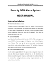
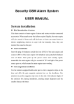
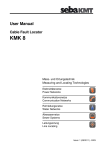
Installation Instructions
(220V Single-phase Input using ABB ACS550 VFD)
1
TABLE OF CONTENTS
Parts List ………………………………………………….………... Page 3
Fan Placement, Spacing, and Clearance ………….……..….…. Page 4
Fan Maintenance ……………………………………………….…. Page 4
Installation Instructions ………………………….…………….….. Page 5
Control Keypad Instructions ……………………………………… Page 16
Daisy Chaining …………………………………………………….. Page 20
2
MECHANICAL ITEMS INCLUDED IN YOUR SHIPMENT
5 Fan Blades
5 Fan Blade Flaps
5 Fan Blade End Caps
1 Fan Drive Assembly
1 Beam Mounting Bracket
3 ¼” Turnbuckles with jam nuts
Gearbox Vent (Must be installed)
Bolts, nuts, washers, and clamps of various sizes (see Installation Instructions for types and
quantities)
ELECTRICAL ITEMS INCLUDED IN YOUR SHIPMENT
1 Lockable disconnect with installation instructions
- 1 ABB ACS550 Variable Frequency Drive (VFD) with remote keypad
a. One (1) VFD mounting bracket and hardware kit
b. 100 ft. of Cat 6 cable (with RJ45 connectors)
c. Three (3) wire crimps for motor control cable
d. One (1) Cat 6 cable strain relief
e. One (1) Remote control keypad box
f. One (1) ACS550 drive User’s Manual
g. One (1) motor control cable (fan motor to VFD)
h. Two (2) motor cable strain reliefs
FAN SAFETY COMPONENTS PROVIDED
Drive Assembly safety cable (1)
Guy wires (3)
Blade Safety Brackets (5)
TOOLS TO GET STARTED
Scissor lift
Wrench and socket set (5/16”-3/4” needed)
Cordless power driver with clutch and Phillips Bit
1/4” Nut driver
Torque wrench
Standard and Phillips screwdrivers
Instrument screwdriver (1/8” flat blade)
Wire stripper/cutter
Level
3/16” “L” shaped Allen wrench
Three (3) beam clamps with eye bolts
Check that all necessary parts are included with your shipment. Should an item be missing,
contact Patterson immediately at (800) 768-3985.
3
Note: In order to protect personnel, equipment, and the fan, it is important that all safety
components are installed per these instructions. Failure to properly install any or all of these
safeguards may void the manufacturer’s warranty. Electrical installation should be
performed by a licensed electrician.
FAN SPACING, PLACEMENT, AND CLEARANCE
Fans should be mounted such that the blades are a minimum of 10 feet above the floor. The
ideal height is 20 to 25 feet. Also, ensure that the fan blades have a clearance equal to 15%
of the fan’s diameter in all directions.
Care should be taken when installing the fan around a fire sprinkler system. The VFD is
equipped with the ability to connect to a fire suppression system – stopping the fans in case
of a fire. However, it is the responsibility of the installer to read and comply with all local
codes and regulations.
MAINTENANCE
Prior to performing any maintenance on the fan, it MUST be disconnected from the power
source by means of the separate lockable disconnect provided.
VFD Box – Clean heat dissipating fins on the back of the box periodically.
Gearbox – Periodic maintenance will ensure your fan remains operational for its intended
life. While Patterson recommends the end-user check and change the gearbox oil annually,
failure to do so will not void any warranties. Oil type used is Chevron® Delo Gear ESI 85W140. Contact Patterson at (800) 768-3985 for availability.
Hub Grease – Hub should be inspected yearly to ensure proper lubrication. Grease type is
Chevron Delo HD Moly 5%. There are two grease fittings, an upper and lower. Add grease
as needed, filling each area slowly until grease passes through the upper seal.
Mounting Hardware – All nuts and bolts related to mounting of the fan unit should be
checked for tightness annually. In addition, guy wires need to be inspected to ensure they
remain taut and show no signs of fraying.
Blades – Blades can be occasionally wiped down with a damp cloth. A mild detergent can
also be used if desired.
4
INSTALLATION PROCEDURES
Step 1: Attach Mounting Bracket and VFD Bracket to Structure
A) It is important to attach the mounting bracket to the structure first and then connect the
fan assembly.
B) Refer to Image 1 to determine which set of bolt slots to use:
Image 1
i)
ii)
For I-beam width less than 7¼”, use slots labeled “A”. I-beams wider
than 7¼” should use slots labeled “B”.
For I-beam thickness greater than ½”, use the provided spacer as shown
in Image 2.
Image 2
5
iii)
iv)
Attach clamp to structure, torqueing GRADE 8 ½” bolts to 80 ft-lbs.
(OPTIONAL) When attaching the mounting bracket to added “bridges”
between two or more points of an existing structure (i.e. bar joists, Zpurlins, etc.), orient the beam plate as shown in Image 3. This will ensure
guy wire cables are properly aligned with the structure. In this
configuration, the beam clamps will NOT be necessary. Also, longer
GRADE 8 ½” bolts are needed (not provided).
Image 3
v)
Using the hardware provided, attach the VFD to the VFD bracket. Then
attach the VFD/bracket combination to the mounting plate by means of
the two (2) pre-drilled holes (see Image 3). A properly installed VFD is
shown in Image 4.
Image 4
6
INSTALLER Please Note: Customers may request that the VFD NOT be
mounted on the fan so that it can be accessed. It is important to
emphasize that after installation, there is no reason to get to the drive.
ALL of the information, resets, error codes and parameters are accessed
from the remote keypad only. If the customer insists, Belden 29522C MultiConductor 600V VFD cable should be used. Failure to use proper VFD
cable may result in operational issues with the drive or fan and can
shorten life expectancy.
vi)
If a down rod was ordered, remove the 4¾” connector and replace with
the longer down rod. Refer to Image 2.
Step 2: Attach Fan Assembly to Mounting Hardware
A) Using a scissor lift, raise the fan assembly and guide the connector (or down rod) into
the tube on top of the fan frame until its mounting holes line up (see Image 5).
Image 5
Image 6
B) Secure the fan to the swivel assembly (or end of down rod) as shown in Image 6.
Torque bolts to 35 ft-lbs.
7
Step 3: Install Fan Assembly Safety Cable
Note: This step is required. Failure to install the safety cable may void the
manufacturer’s warranty.
A) Pass one end of the safety cable underneath where the three vertical frame members
join together (at the top of the fan drive assembly).
B) The opposite end of the safety cable should be passed over the top of the I-beam or
other mounting structure. Connect the two ends of the cable together by means of 3
saddle clamps (provided) in the manner shown in Image 7.
C) Tighten the saddle clamps securely using a ½” socket. Torque to 15 ft-lbs
Image 7
8
Step 4: Connect Both Ends of the Motor Control Cable
Reference: Pages 16-32 of the ACS550 User’s Manual
A) Remove the cover of the VFD using the steps shown on page 17 of the “ACS550
User’s Manual” under the heading “IP 54 / UL Type 12”.
B) Remove the cable seals located on the bottom of the drive as needed. A total of three
cable seals must be removed to accommodate the motor cable, power cable, and Cat
6 cable.
C) Pass the cable conductors and shielding through one of the provided strain reliefs, and
then through one of the holes on the bottom of the VFD.
D) Connect one end of the motor control cable to the VFD in the manner shown on page
29 of the “ACS550 User’s Manual.” The three conductors should be connected to U2,
V2, and W2, respectively, using the three (3) yellow wire crimps. The cable foil shield
should be secured by the cable clamp as shown in Image 8.
E) Connect the opposite end of the motor control cable to the fan motor. This will require
removal of one of the knockouts on the motor’s junction box. As before, pass the
cable conductors and shielding through the strain relief, and then through the junction
box hole. The wiring configuration is input voltage dependent. Please wire the
motor properly using the wiring diagrams found on the fan motor’s nameplate.
F) Once cable is properly connected at both ends, tighten down the strain reliefs.
Step 5: Run Input Power to Drive and Install Lockable Disconnect
References: Pages 16-32 of the ACS550 User’s Manual
Lockable Disconnect Installation Instructions
WARNING: The Lockable Disconnect must be installed per local electrical
codes. AT MINIMUM it must be installed outside the diameter of the fan
blades.
A) Run input power into the top of the Lockable Disconnect, using the appropriately sized
knockout.
B) Connect conductors to terminals L1and L2, respectively. Ground wire should be
fastened to the protective earth (PE).
C) On the output side, T2 should be looped back to input L3.
D) Continue running input power to the drive by connecting two conductors to terminals
T1 and T3, respectively. A ground wire should be fastened to the protective earth (PE)
provided.
9
E) Connect the opposite end of the input power cable to the VFD in the manner shown on
page 29 of the “ACS550 User’s Manual.” The two conductors should be connected to
U1 and W1, respectively. The ground wire should be connected in the manner shown
in Image 8.
F) A successfully wired drive should appear like Image 8.
Image 8
Cat 6 Cable
Receptacle
DIP Switches
VFD I/O
Terminal Blocks
Factory Installed
Jumpers
Input Voltage
Wiring
Input Voltage
Ground Wire
Motor Control
Cable
Motor Control
Cable Shielding
10
Step 6: Install Guy Wires
Note: For maximum stability, the angle formed between the guy wire and the ceiling should
be less than 45 degrees.
This step is required. Failure to install the guy wires properly may void the
manufacturer’s warranty AND become a safety hazard.
The following steps should be performed with the aid of a scissor lift.
Image 9
A) Attach the looped end of the guy wire to the turnbuckle located on the fan assembly. It
should appear like the Image 10.
Image 10
11
B) Pass the opposite end of the guy wire through the eye bolt of a beam clamp (not
supplied). Thimbles must be used to protect the cable from damage.
C) Reduce the slack in each cable, making sure the fan assembly remains in the vertical
position. Use 3 saddle clamps to crimp the end of the guy wire together as shown in
Image 11. Ensure saddle clamps are positioned so that the teeth on the nut side grab
the end of the cable that is most likely to slip.
Image 11
D) Repeat steps A – C for the remaining two guy wires.
E) Once all guy wires are in place, use the turnbuckles to take out any remaining slack.
Periodically check the fan assembly with a level to ensure it remains in the vertical
position. Continue adjusting by means of the turnbuckles until all cables are
satisfactory. Guy wires should be taut, but not over stressed. Recheck all saddle
clamps for tightness.
F) Tighten all jam nuts on turn buckles (Image 12). This step is required. Failure to
install the guy wires properly may void the manufacturer’s warranty AND
become a safety hazard.
Image 12
12
Step 7: Install Fan Blades & Secure Blade Safety Bracket
A) Care should be taken when installing the blades to ensure they are not bent or
damaged, as this may affect fan performance.
B) Remove blade bolts, nuts, and washers from blade “paddle” on the fan’s hub. Loosen
Safety Bracket bolt (shown in Image 13) until the bracket moves freely. Carefully slide
the fan blade into position until all blade bolt holes on the fan, blade, and safety
bracket are aligned. Replace blade bolts, nuts, and washers. Torque to 65 ft-lbs.
C) Tighten the 3/8” Safety Bracket bolt on the other end of the blade safety bracket.
Image 13
D) Install blade flaps using ¼” bolts and end caps using #10 x ½” screws provided.
Ensure ¼” bolts are tight on flaps. The pan head of the bolts go into the countersinks
in the bottom of the blades. Refer to Image 14 for more information.
13
Image 14
E) Repeat steps B – D for the remaining 4 blades.
Step 8: Remove Plug in Cap of Gearbox
Note: This step is required. Failure to remove the plug may cause gearbox seals to
leak due to pressurization of the lubrication fluid, possibly voiding the manufacturer’s
warranty.
A) Remove plug in the gearbox and replace with vent prior to operation of the fan.
The vent fitting is in a bag that is affixed to the frame at the location
of the plug.
Step 9: Mount the Remote Keypad Enclosure and Connect to VFD
Note: It is vitally important that the remote keypad is ALWAYS mounted
outside the blade radius of the fan. This is especially important for the
daisy chaining configuration (see page 20). The daisy chaining process
requires access to the keypad while the fan is in motion.
A) Once a desired location is found, affix the remote keypad to the wall using the
mounting pads attached to the keypad enclosure.
B) Run the Cat 6 cable up to the fan-mounted VFD via the shortest possible path. If
possible, avoid lighting and other noise-producing electrical equipment. Running the
cable inside conduit is optional.
14
C) Pass the Cat 6 cable through the strain relief and then into the bottom of the drive.
Connect the cable to the appropriate receptacle on the face of the VFD (see Image 8
on page 10). Be sure to tighten the strain relief on the bottom of the VFD.
D) Replace the cover of the VFD using the steps show on page 32 of the “ACS550 User’s
Manual,” under the heading “IP 54 / UL Type 12”.
Step 10: Connect the VFD to the Fire Suppression System (OPTIONAL)
Please Note: If the drive will not be connected to any fire suppression
system, the factory installed jumper across 10 & 16 MUST remain in place.
A) Remove the factory installed jumper between terminals 10 and 16. The terminal block
is located at the left side of the ACS550. For more information, refer to Image 8 on
page 10.
B) Connect the fire suppression system wires to terminals 10 and 16. Again, the fire
system cable will enter the drive enclosure through the bottom (additional cable seal
must be removed).
C) Drive is now wired to shut down upon activation of any fire suppression signal.
This completes the installation of your High-5 Fan.
15
Fan Control
Keypad Instructions
CAUTION: Please read carefully and completely before fan operation.
FAN ROTATION: Proper rotation is achieved when the directional
indicator (#3 in Image 15) is clockwise and the blade flaps are trailing. If
rotation is not correct, swapping two of the motor wires (L1, L2 or L3) in
the motor junction box will change the rotation.
16
IMAGE 15
1
2
4
3
3
3
3
3
3
5a
3
5b
5c
6
3
3
7
3
8
3
9
3
3
3
3
10
3
3
17
CONTROL KEYPAD FEATURES
1. Status LED:
a. Green – Normal Operation
b. Blinking Green – Fan drive is in alarm. Consult the drive’s User Manual for
alarm conditions.
c. Red – Fan drive has faulted. Consult the drive’s User Manual for fault
conditions.
2. LOC/REM Indicator: Indicates whether the drive is in local or remote control. See
LOC/REM button entry below for more detail.
3. Rotation Indicator: Indicates rotation of the fan motor shaft (and fan blades). See
item #2 in the section entitled Additional Information.
4. Fan Speed Set Point: Indicates fan speed as a percent of maximum (%). This
percentage corresponds to a read-only RPM reading (see #5 below). Can be adjusted
using the up and down arrows (see #7 below).
5. Read-Only Parameters: Give real-time readouts of the following conditions:
a. Fan speed – Expressed in RPM (see #4 above)
b. Fan motor amperage – Indicates the current being drawn by the fan motor,
expressed in Amperes (A)
c. Fan motor torque – Indicates fan motor output torque, expressed in percentage
(%)
6. Soft Keys: Located directly below functions displayed in the lower corners of the
keypad screen. Right Soft Key is generally not used during basic fan operation. Left
Soft Key controls fan direction. See section entitled Additional Information.
7. Up/Down Arrows: Allow for adjustment of the Fan Speed Set Point (either while the
fan is stopped or in motion). See section entitled Fan Operation.
8. LOC/REM Button: Toggles between local and remote control of the fan drive. If LOC
is displayed in the upper left corner of the keypad screen, control of the drive is
initiated locally (i.e. from the keypad). If REM is displayed, control is initiated from an
external source (i.e. another drive or fieldbus).
9. Help Button: Provides more information during drive programming. Not used for fan
operation.
10. Start/Stop Buttons: Used to start and stop the fan. See section entitled Fan
Operation.
18
FAN OPERATION
Starting the Fan:
1. Make sure the LOC/REM Indicator shows the fan drive is in local (LOC) mode. The
fan will not respond to inputs from the keypad if the drive is in remote (REM) mode.
Use the LOC/REM Button as needed to ensure local control.
2. Using the Up/Down Arrow keys, adjust the Fan Speed Set Point. Remember, the Fan
Speed Set Point is based on percentage of maximum speed. This percentage
corresponds to the read-only RPM indicator.
3. Press the START button, and allow the fan to ramp up to speed. This may take a few
seconds. To prevent damage to the gearbox, it is recommended that the fan reach its
Set Point speed before making any further adjustments.
4. If the initial Set Point adjustment is unsatisfactory, refer to the section below entitled
“Adjusting Fan Speed While in Motion” to achieve the desired fan RPM.
Adjusting Fan Speed While in Motion:
1. Ensure local (LOC) control of the drive (see above).
2. Use the Up/Down Arrow keys to adjust the Fan Speed Set Point as desired. For best
results, use the Read-Only Fan Speed indicator (in RPMs) as a gauge for your
desired setting. The fan will then ramp up or down in response to the changing input.
3. Caution: DO NOT adjust the Fan Speed up and down repeatedly in
large increments. Allow the fan to reach the new speed before
making any further adjustments.
Stopping the Fan:
1. Ensure local (LOC) control of the drive (see above).
2. Press the STOP button. The fan will then ramp down to a complete stop. This may
take a few seconds. Allow the fan to stop COMPLETELY before
restarting.
19
ADDITIONAL INFORMATION
1. Fan drives are programmed prior to shipment. In order to ensure continuity, drive
parameters are locked by means of a three-digit passcode. Should troubleshooting of
the drive become necessary, contact Patterson at (800) 768-3985. A passcode can
then be given to unlock the drive’s parameters. It is highly recommended that the
parameters be relocked (using the same passcode) prior to putting the fan back in
service.
2. Patterson’s High-5 fans are designed to maximize air movement while spinning in the
FORWARD direction. However, they can be run in REVERSE. Follow these steps:
a. If the fan is stopped, press the left Soft Key with the letters “DIR” above it.
When the fan is started, it will run in the reverse direction.
b. If the fan is running, press the STOP button, and allow the fan to come to a
complete stop. Then press the left Soft Key with the letters “DIR” above it.
When the fan is started, it will run in the reverse direction.
3. Please be aware that each fan is programmed to have a minimum fan speed, set at
some level above 0%. This is to protect the fan motor. The minimum speed will vary
depending on the size of the fan.
Daisy Chaining
Daisy chaining is a set up by which the output of one VFD is tied to the input of the next VFD
downstream. This allows for a master/follower configuration. The “master” fan remains in
LOCAL mode, while all the “followers” are set to REMOTE. The followers will then rotate at
the same speed as the master fan.
Note: Any fan in the daisy chain can be set to LOCAL (LOC) mode for local control.
However, all of the fans downstream will then begin to rotate at the speed
of that fan, NOT the designated master.
Each follower must be wired according to the diagram on page 21. The VFD designated as
the master will be wired in exactly the same manner, but without wiring ANYTHING
into terminals 2 and 3 on the VFD.
20
Key Points for Daisy Chaining:
1. Wire for daisy chaining must be: 2-conductor with ground, 18 AWG, double shielded.
2. Based on the wiring diagram, please note that only the “to downstream drive” end of
the daisy chain wire shield is connected to the drive at terminal 1. The shield on the
input side (terminals 2 and 3) is not connected.
3. Please note the series of jumpers in the above diagram. These must be connected in
addition to the daisy chain input/output wiring. Two of the jumpers are already factory
installed (see below). The rest must be connected at the time of fan installation. The
numbers in the diagram correspond to numbers on the drive’s terminal block (see
Image 8 on page 10 of these instructions).
Factory installed jumpers – 11 & 12 / 10 & 16
Field installed jumpers – 10 & 19 / 10 & 22 / 13 & 20 / 13 & 23
21
4. Make sure that the DIP switch labeled “1” is in the ON (or right) position. This switch is
located above I/O terminal block pin #1. Refer to Image 8 on page 10 for more
information.
5. To reduce noise and potential drive interruption, it is recommended that daisy chain
wire be run through conduit.
6. Speed scaling: Because of line losses, downstream followers may initially rotate at
a slower speed than that of the master. To rectify this problem, perform these steps:
Make sure the “master” fan is in LOCAL mode and all “followers” are in
REMOTE mode. If it is safe to do so, turn the master fan on to maximum
speed. All fans should begin spinning at this time. Note the maximum
speed on the master unit’s keypad (in RPMs).
a. Go to the first downstream follower. If the unit is rotating at the same speed
as the master, no additional action is necessary. However, if the speed is
slower than the master, go to Step (b).
b. Unlock the follower’s parameter set.
i.
Set the fan in local mode by pressing the LOC/REM button.
ii.
Press the MENU key on the keypad.
iii.
Highlight the PARAMETERS option. Press ENTER.
iv.
Use the up/down arrow keys to highlight parameter group 16. Press
SELECT.
v.
Scroll down to parameter 1603 PASS CODE. Enter the pass code
shown next to the parameter’s description on page 125 of the
“ACS550 User’s Manual.” You will use the up/down arrow keys to
enter the code. Once entered, press the SAVE key.
vi.
Scroll up and select parameter 1602 PARAMETER LOCK. Using
the arrow keys, change the status from LOCKED to OPEN. Press
the SAVE key.
vii.
Continue pressing the EXIT key until you arrive at the keypad’s
output screen. Return the fan to REMOTE mode by pressing the
LOC/REM button.
viii.
Go to Step (c).
c. Once the parameter set has been unlocked, the fan speed will need to be
scaled to match that of the master. To accomplish this:
i.
Press the MENU key on the keypad.
ii.
Highlight the PARAMETERS option. Press ENTER.
iii.
Use the up/down arrow keys to highlight parameter group 01. Press
SELECT.
iv.
Scroll down to parameter 0120 AI 1. This is a read-only parameter.
Jot down or remember its value, expressed as a percentage (%).
Press EXIT until you reach the keypad output screen.
v.
Place the fan in LOCAL control by pressing the LOC/REM button.
vi.
Navigate back to parameter group 13. Press SELECT.
vii.
Find parameter 1302 MAXIMUM AI1. Using the arrow keys, enter the
percentage from parameter 0120. Press the SAVE key.
22
viii.
Press EXIT until you reach the keypad output screen. Return the fan
to REMOTE mode. The fan should immediately start to speed up to
match the master.
d. Repeat Steps (b) – (c) for each additional downstream follower. It is
advisable to re-lock each fan’s parameter set after adjusting the speed
scale, reversing the instructions in Step (b). This will prevent unnecessary
tampering with fan drive parameters.
e. Once all followers have been properly scaled, return to the master fan and
set the desired speed for the daisy-chained system.
For additional questions concerning the daisy chain configuration,
contact Patterson engineering at (800) 768-3985.
This completes the High-5 Keypad Instructions.
23