1
www.deutschermowers.com.au
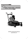
DEUTSCHER MOWERS
DEUTSCHER
XE560
OWNER’S MANUAL
INDEX
2
Initial Assembly
3
Safety Instructions
4
Maintenance & Storage
5
Specifications & Controls
6-7
Mowing & Transporting
8-9
Maintenance
10
Mower Decals
11-15
16
Exploded Views & Parts Lists
Warranty
INITIAL ASSEMBLY
(Tools Required:
Two 13mm open-ended spanners)
1. Remove the mower from the packaging and visually check for damage.
2. Raise the mower handle to its normal position until the holes in the plates at the bottom of the handles align
with the holes in the engine mounting plate. Insert the 8mm x 20mm bolts in the two holes, attach nuts then
tighten all four handle attachment bolts.
3. Insert the end of the vertical gear change rod on the left side of the handle through the hole in the short lever
on the left side of the engine plate, then insert an R clip through the small hole in the end of the rod.
4. Raise the foot operated clutch pedal and insert the end of the 10mm rod under the engine plate into the hole in
the end of the clutch pedal lever. Insert an R clip into the hole in the end of the rod.
5. Thread the mower cord through the guide on the righthand handle.
vertical gear
change rod
R clip
foot operated
clutch pedal
2
10mm rod
SAFETY INSTRUCTIONS
!
1. Know your controls. Read the owners manuals thoroughly. Learn how to stop the engine quickly in an
emergency.
2. Inspect the area to be mown, remove all debris and obstacles that may be in the path of the mower. Do not
attempt to shift obstacles while engine is running.
3. To avoid sunburn, apply sunscreen; wear appropriate clothing, a hat and sunglasses.
4. Damaged blades and worn bolts are major hazards. Before starting, always visually inspect to see that blades,
blade bolts and cutter assemblies are not worn or damaged. Replace worn or damaged blades and bolts in sets
top preserve balance.
5. Do not allow children or people unfamiliar with these instructions to use the mower.
6. With prolonged use, hearing protection should be worn.
7. Never mow while barefoot or wearing open sandals or thongs. Wear long trousers and heavy duty shoes.
8. It is advisable to wear suitable eye protection when operating the mower.
9. Refuel outdoors only, well clear of any sources of ignition, including pilot lights on gas appliances. Do not
smoke while refuelling engine. Add fuel before starting the engine. Never remove the fuel tank cap or add petrol
while the engine is running or while the engine is hot. If petrol is spilled, do not attempt to start the engine but
move the machine away from the area of the spill and avoid creating any source of ignition until the petrol
vapours have dissipated.
10. Before starting the engine, ensure blades are disengaged by checking that the foot pedal is in its highest
position.
11. Start the mower carefully according to instructions. Keep feet well away from the blades and do not stand
in front of the discharge chute.
12. Never mow while people or pets are nearby.
13. Mow only in daylight. Stay alert for holes in the terrain and other hidden hazards.
14. Keep bystanders away from the mower when it is operating.
15. Avoid operating the equipment in wet grass, where feasible.
16. Do not put hands and feet near or under rotating parts. Keep clear of the discharge opening at all times.
17. Never pick up or carry a mower while the engine is running.
18. Use extreme caution when reversing or pulling mower towards you.
19. Do not carry passengers.
20. Walk, never run.
3
SAFETY INSTRUCTIONS
21. SLOPES
• Do not mow excessively steep slopes.
• Exercise extreme caution when on slopes.
• Mow across the face of slopes, never up and down and exercise extreme caution when changing direction
on slopes.
• Never leave the mower unattended on a slope.
22. Normally start mowing in low gear until you are sure of the speed needed for the task.
23. Stop the blades when crossing surfaces other than grass and when transporting the mower to and from the
area to be mowed.
24. Do not operate the engine in a confined space where dangerous fumes can collect.
25. Stop the engine before refuelling and whenever you leave the mower.
26. Watch out for traffic when crossing or near roadways.
27. STOP THE ENGINE AND DISCONNECT THE SPARK-PLUG LEAD
• Before clearing blockages or unclogging chute:
• Before checking, cleaning or working on the mower:
• After striking a foreign object. (Inspect the mower for damage and make repairs before restarting and
operating the mower).
• If mower starts to vibrate abnormally, stop the engine immediately.
28. STORAGE SAFETY
• Keep all nuts, bolts and screws tight to be sure the equipment is in safe working condition.
• Do not use pressure-cleaning equipment.
• Never store the equipment with petrol in the tank inside a building where fumes can reach an open flame
or spark.
• Allow the engine to cool before storing in any enclosure.
• To reduce fire hazard, keep the engine, muffler and petrol storage area free of grass, leaves, or excessive
grease.
• If the fuel tank has to be drained, do this out-doors and away from sources of ignition.
• Store fuel in a cool place in a designated fuel container. Metal containers are preferred and only plastic
containers specifically designed for holding fuel are suitable.
• Turn fuel tap off when storing the mower.
29. MAINTENANCE SAFETY
• Replace worn or damaged parts for safety, especially the blades.
• Replace faulty muffler.
• Do not change the engine governor settings or over speed the engine. Operating an engine at excessive
speed can increase the hazard to personal injury.
• Be careful during adjustment of the mower to prevent entrapment of the fingers between moving blades
and fixed parts of the mower.
Do not modify this mower in any way, or use the mower without shields or guards
in place. They are for your protection!
4
SPECIFICATIONS & CONTROLS
SPECIFICATIONS
MODEL No:
36214 XE560 with 850 series Briggs and Stratton engine.
36215 XE560 with a GSV190 Honda engine.
Consult engine owners manual for engine specifications.
TRANSAXLE:
High and Low gear plus a differential is incorporated in the transaxle. A clutch lever to engage and
disengage the drive belt is positioned on the right hand handle. A gear change lever is provided on the
left side of the control panel.
MOWER SPEED:
Low gear: 2.9 kph @ 3000rpm.
High gear: 4.2 kph @ 3000rpm.
TYRES:
Rear: 410 –350 - 6 Pressure, 25psi
Front: 170 dia
Solid rubber tyre
CUTTING HEAD:
560mm cut, 2 x blades, 7 cutting hight positions from 22mm- 75mm.
DIMENSIONS:
Length:1620 mm, Width 680 mm, Height: 965 mm, Weight:75 kg
CONTROLS
Gear Change Lever
Raise & Lower Lever
Wheel Drive Lever
Throttle Control
Cutter Engage Pedal
5
MOWING AND TRANSPORTING
PRE-START CHECK:
Ensure engine oil is at the correct level before starting. See engine manual for instructions. Your Deutscher
Mower comes to you with the transmission filled with oil.
• Use fresh unleaded petrol. Do not mix oil with petrol.
• Read all safety instructions and know how to stop the engine quickly in any emergency.
• Know your controls – Where they are and their function
STARTING AND STOPPING:
TO START THE ENGINE: First ensure the blades are disengaged. (Pedal up) and the fuel tap is turned on.
• When engine is cold, move the throttle lever to the FAST position.
• When engine is hot, move throttle lever to mid throttle position.
• Slowly pull the starter cord until the starter pawls engage and the rope stops, then pull with sufficient force to
overcome the engine compression. Lower the cord back to the guide on the mower handle.
• Once the engine is running, move the throttle lever to the desired operating position.
TO STOP THE ENGINE:
• Push the throttle lever to the STOP position.
OPERATING:
With the mower on relatively level ground and the area clear of bystanders and debris.
• Engaging cutters: With the engine running at fast speed, slowly push down on the “cutter engagement pedal”
with your left foot.
• Selecting forward speed: With the cutters engaged and no pressure on the clutch lever on the right handle,
pull backwards on the “gear change lever” to select slow speed, to the centre for “neutral” speed or forward
for high speed. If the gear does not engage easily, move the mower forward a short distance while applying
light pressure on the lever.
• Selecting height: Stand to the left of the mower handle and keep your feet well clear of the mowing deck. Lift
the “Raise and Lower” lever and move it to the desired height setting. ( Fully back towards the rear of the mower
for mowing long grass.) Release the lever and ensure the pin engages in one of the slots in the quadrant.
• Adjusting the throttle control to the desired position: Best cutting is achieved at a high throttle setting and
slow forward speed, but to minimise cutting time the fast forward speed may be selected.
• Driving forward: Once the appropriate gear is selected, slowly squeeze the lever on the right handle and the
mower will move. If the drive is slipping on steep slopes, the nuts on the wheel drive rod can be adjusted. (See
Maintenance section).
• Moving backwards: Warning, be very careful of your footing when pulling the mower backwards. Release
the clutch lever on the right handle and pull backwards slowly. This is much easier with the gear lever set to
neutral.
• Warning: Never leave the mower running whilst unattended. Always turn off the mower to clear debris or
check the mower.
6
MOWING AND TRANSPORTING
MOWING ON SLOPES:
• Reduce speed on slopes and in sharp turns to prevent overturning and loss of control. Mow across the face
of slopes, never up and down.
• Maintain a firm grip on the handles, as the mower will run away if released.
• Wear suitable boots for the terrain. Do not continue mowing if you are slipping while walking. Exercise extreme
caution if the grass is damp.
• Do not mow an area with a slope greater than 12 degrees to the horizontal.
• Be extremely cautious when pulling the mower backwards. This is particularly important on slopes. Wear
strong non - slip footwear and keep well back from the mower.
• Never leave the mower parked on a slope. This applies even if you leave the mower for an instant.
TRANSPORTING
Always turn the fuel tap off when transporting.
It is easier to transport the mower in a trailer, using ramps to drive the mower into position. Select “low” gear
and a low throttle setting when driving up ramps. Ensure the ramps are not too steep or slippery. Firmly tie the
mower in position once it is in the trailer.
The XE560 mower will fit in the back of a family sized station wagon, with the handle folded down. Never attempt
to lift the mower on your own, and always secure the mower from moving once it is in place.
TO FOLD THE HANDLE:
• Remove the rear handle attachment bolts on each side of the engine mounting plate,
• Withdraw the clip from the lower end of the gear change lever control rod, and move the rod clear of the
lower lever.
• Disengage the starting cord from the guide on the right hand handle and allow the starting handle to
withdraw to the engine cover.
• Loosen the front two handle attachment bolts while holding the handle to prevent it falling.
• Fold the handle forward. Ensure that the handle clears the “raise and lower” lever as it is lowered onto
the front cover. Place a rag or other soft material under the handle if you wish to protect the paint on the
front cover.
7
MAINTENANCE
Frequency
Part
Task
Engine
8 hrs
20 hrs
100 hrs
Refer to Engine Manual
Transaxle
Check oil level
Cutter spindle
X
Check sealed bearings
King pins
Oil
Raise & lower frame slides
X
X
Grease
X
Blades and drive belts
Check, replace if necessary
X
Clutch control linkages
Oil
X
Height control linkages
Oil
X
Throttle cable
Oil
X
Note: IF ABNORMAL NOISES OR VIBRATIONS ARE HEARD OR OBSERVED, STOP THE MOWER AND CHECK
IMMEDIATELY. DO NOT WAIT FOR THE NEXT SCHEDULED SERVICE
GEARBOX
Use gear oil 85W140
Capacity = 750ml
FILL GEAR BOX TO THIS LEVEL
KING PINS: FRONT WHEELS
Oil every 8 hours, by applying a few drops of oil on the upper and lower bronze bushes.
TRANSAXLE BELT ADJUSTMENT(Tools required….2 off 13mm open ended spanners)
On the right hand side of the mower (when standing at the handles) is a vertical control rod that can be adjusted
at its top end using the two nuts on the threaded end of the rod.
If the drive is slipping, firstly inspect the short belt under the engine plate to ensure it is still in sound condition.
( Replace if it is in poor condition.) Next lengthen the threaded control rod by moving the nuts on the threaded
section upwards. Initially try one or two turns of the nuts, as over-tensioning the belt can lead to premature belt
wear and a high engagement load on the control lever.
To test the drive, simply start the engine on level ground, put the gear lever into “low” speed and try holding
the mower back while slowly squeezing the drive lever on the right handle. If the drive still slips, slightly more
adjustment may be needed.
!
8
• Before any inspection or replacements of the belts and associated parts turn engine off and
remove the spark plug lead from the spark plug.
• Be careful during adjustment of the mower to prevent entrapment of the fingers between blades,
pulley’s and fixed parts of the mower.
• Only replace the spark plug lead once all adjustments are completed and guards are replaced.
MAINTENANCE
TRANSAXLE BELT: REPLACEMENT (Tools required…2 x 13mm spanners, 1 x phillips head screwdriver.)
• To remove the belt, firstly remove the top cover by withdrawing the 4 securing screws.
• Loosen the nuts on the top end of the vertical control rod using two 13mm spanners. Screw the lower nut down
on the thread so the tension on the belt from the idler pulley is minimised.
• From behind the mower, roll the drive belt off the engine pulley. Then withdraw the belt from the front pulleys.
• Replace the belt with a new belt (Deutscher part No. 1579), and ensure the belt is inside the guide pins.
• Re-adjust the vertical rod length using the two nuts so the drive belt is taught when the hand lever on the right
handle is just touching the rubber handle grip. Excessive belt tension may not improve drive traction and may
cause premature belt wear.
CUTTER BELT: REPLACEMENT, including BLADE BRAKE ADJUSTMENT
(Tools required…2 x 18mm open ended spanners, 2 x 11mm open ended spanners, 1 x phillips head
screwdriver. )
• To replace the cutter belt, first remove the top cover. Next ensure that the drive belt is disengaged, by raising
the foot pedal on the rear of the mower.
• Fully loosen the front ¼” nut on the blade brake rod alongside the left rail of the mower.
• Loosen the two large 12mm nuts on the threaded rod attached to the cutter spindle. Wind the nuts by hand on
the threaded rod to allow the cutter deck to be pushed fully back in its slides.
• Remove the transaxle drive belt as described above.
• Install a new blade drive belt and then replace the transaxle drive belt.
• Readjust the two 12mm nuts by hand tightening them, engaging the blade drive foot pedal and checking the belt
tension. The easiest way to test the tension is to squeeze the belt together somewhere near the centre between
the two pulleys. The belt should only move in about 15mm on each side.
• Securely lock the two 12mm nuts.
• Re-adjust the blade brake rod by engaging the clutch and moving the brake pad so it is 1-2 mm clear of the
spindle pulley. Tighten the 1/4” nuts.
• Test run the mower, keeping well clear of the drive belts. Ensure that the blade brake operates when the blade
drive clutch is disengaged.
BLADES
• It is important that you visually inspect the blades, bolts and nuts to ensure that they are in a safe operating
condition; this should be done before each mowing period.
• Always replace blades and bolts in kit form to prevent any vibration that may damage the mower and cause
personal injury.
Nut
Washer
Blade Plate
Blade
Bolt
9
MOWER DECALS
3346
3349
3348
HIGH
NEUTRAL
LOW
3351
3347
THROTTLE
STOP
DEUTSCHER
XE560
TWO SPEED
FAST
G
E
A
R
S
Read operating
instructions before use.
DRIVE
Raise lever
to drive
forward.
Release to
dis-engage.
3352
3350
10
EXPLODED VIEWS AND PARTS LISTS
XE560 CHASSIS AND COMPONENTS
41
40
Item No
1
Part No
1017
Part Description ( Qty )
Bolt M8 x 20
Item No
22
Part No
1854
Part Description ( Qty )
Connecting rod, deck lift
2
1018
Spring washer 8mm
23
1495
Special bolt
3
1144
Plain washer 8mm
24
1061
Nut 3/8” UNC
4
1485
Bolt ¼” x 1” W
25
1062
Nyloc nut 3/8” UNC
5
1482
Wheel half (4)
26
3265
Top cover
6
1838
Front tyre
27
3231
Blade engage foot pedal
7
1484
Front wheel bearing (4)
28
3233
Clutch rod (cutter engage)
8
1486
¼” W nut
29
1184
R clip
9
2099
King pin & stub axle, RH
30
1341
Split pin
10
2098
King pin & stub axle, LH
31
1918
Rear tyre
11
Y555
Front wheel Assy.
32
RD204
Tube
12
3015
Flanged bronze bush (4)
33
Z81
Rear wheel rims
13
1017
Bolt M8 x 20
34
1495
Special bolt
14
1970
Chassis welded assembly
35
3234
Clutch pivot plate, wheel drive
15
1487
Deck lift spring
36
1781
Pulley bush
Idler pulley
Horizontal clutch rod
(transmission)
Transmission belt
16
1978
Cap, height lever
37
1518
17
1979
Outer tube, height adjust lever
38
3237
18
3011
Spring, height adjust lever
39
1579
19
3254
Bolt, 6mm x 40, HT.
40
3354
Engine Pulley
20
3230
Gear change lever
41
3367
Collar (Honda Engine only)
21
3240
Gear rod, horizontal
11
EXPLODED VIEWS AND PARTS LISTS
XE560 DECK and COMPONENTS
Item No
Part No
Part Description ( Qty )
Item No
Part No
Part Description ( Qty )
1,3,4,7
H650
Blade, nut, bolt, washer x 2 set
19
2092
Blade brake disc (4)
1,3,4
H652
Nut, bolt, washer x 2 set
20
5350
Bolt , brake bracket (2)
2
1902
Blade plate
18,19,20,21
2093
Brake pad assembly (1)
5
1304
Bolt, blade driver (3)
22
2055
Raise-lower frame
6
1060
Spring washer 3/8”
23
3008
Bolt, deck lift bush (4)
7
H651
Blade set (2 off)
24
1417
Nut, deck lift bush (4)
8
3028
Blade spindle assembly
25
2063
Bush, deck lift
9
1898
Spindle bearing (2)
26
2013
Bush
10
2049
Deck assembly
27
1549
Spring, blade disengage
11
3271
Hinge bar assy
28
1016
Nyloc nut 12mm
12
2095
Plastic sleeve, chute flap (2)
29
2040
Pushrod assembly
13
3273
Discharge flap assembly
30
1244
Nut 12mm plain (2)
14
1328
Belt guide bolt (2)
31
1062
Nut nyloc 3/8” UNF
15
3255
Brake rod pivot
32
2007
Pushrod connector assembly
16
1986
Blade brake rod, threaded
33
1495
Bolt 3/8”, special
17
3276
Brake lever, blade
34
3279
Blade drive pulley assembly
18
1121
Long bolt, brake bracket (1)
35
3290
Blade drive belt
12
EXPLODED VIEWS AND PARTS LISTS
XE560 HANDLE & CONTROLS
16
Item No
Part No.
Part Description
Item No
Part No.
Part Description
1
2
3
4
5
6
7
8
9
10
3261
1017
1072
3238
3172
5028
3239
1495
1062
1586
Handle assembly
Bolt M8 x 20
M8 plain nut
Vertical clutch rod – wheel drive
Pivot, wheel drive clutch
“E” clip
Clutch lever, on handle
Special bolt
Nyloc 3/8” UNC nut
Rubber handle grip
11
12
13
14
15
16
1584
1153
3246
3240
1184
1580
Throttle control
Screw, self threading
Gear change lever assy
Gear change vertical rod
R clip
Cable assembly
13
EXPLODED VIEWS AND PARTS LISTS
XE560 GEARBOX COMPONENTS
52
2
4
5
1
6
3
42
8
7
44
10
43
9
45
12
12
15 14 13
53
11
13
11
14 15
46
47
23
16 17 18
19
20
21
35
31
30
30
25 26 27
48
49
33
40
36
30
29
50
32
30
51
37
39
38
14
28
41
34
29
24
22
EXPLODED VIEWS AND PARTS LISTS
XE560 GEARBOX COMPONENTS
Item No.
Part No.
Qty
Item No.
Part No.
--
3260
Gearbox complete
Part Description
1
27
1637
Washer
Part Description
Qty
1
1
1680
Gear selector arm
1
28
1663
Screw
1
2
1691
Selector tappet
1
29
1659
Seal, axle 7/8”x1,3/8”x1/4”
2
3
1690
O- Ring
1
30
1699
Bearing, needle, roller
4
4
1705
Spring holder
1
31
1673
Left Hand Housing
1
5
1706
Spring
1
32
1689
Bolt ¼ x 2”
6
6
1707
Ball
1
33
1639
Bolt ¼ x 1¼”
1
7
1701
Low crown gear
1
34
1672
Gasket
1
8
1704
Bolt diff
4
35
1664
Bearing 6202
1
9
1700
Spacer, diff.
4
36
1665
Circlip 35mm
1
10
1698
High crown gear
1
37
1708
Right Hand Housing
1
11
1702
Axle
2
38
1654
Plug ¾” UNF
1
12
1501
Drive pin, axle
2
39
1655
Fibre washer ¾”
1
13
1315
Flat washer
2
40
1661
Plug, ½” BSF
2
14
1658
Spring washer
2
41
1662
Fibre washer ½”
2
15
1657
Nut, axle 5/8” UNF
2
42
1100
Screw
1
16
1671
Bearing, roller B98
1
43
1642
Washer
1
17
1721
Circlip, 14mm
1
44
1640
Key
1
18
1720
Pinion, low gear
1
45
1643
Pulley
1
19
1719
Double clutch
1
46
1650
Spacer
1
20
1723
1
47
1651
Seal 25x40x7
1
21
1718
1
48
1652
Circlip 40mm
1
22
1717
Spindle
High gear pinion &
clutch
Hardened washer
1
49
1484
Bearing 6203
1
23
1716
Bronze worm gear
1
50
1653
Input spindle
1
24
1015
Washer
1
51
1656
Bearing roller B128
1
25
3286
14mm nut
1
52
1956
Rear wheel complete
1
26
1714
Bearing sleeve
1
53
1730
Diff spider gear
2
15
WARRANTY POLICY
• DEUTSCHER MOWERS PTY. LTD. will repair or replace, free of charge, any mower or part of a mower that is
defective in materials or workmanship (or both) for a period of 24 months from the date of purchase. If parts
or units are replaced, the replacement period will be no longer than 3 months.
• This does not cover normal wear, abuse or servicing procedures not in accordance with the user’s manual.
Parts such as blades, blade bolts, tyres and v-belts, that can be subject to use beyond their normal intended
working limits, are also excluded.
• This warranty is void if parts other than genuine parts have been used or if repairs or modifications have been
made without the manufactures written authority.
• This warranty does not obligate the manufacturer, agents or dealers to cover transport costs incurred in the
repair or replacement of any defective part. It does not obligate the manufacturer, agents or dealers to cover
any other costs associated with making the warranty claim. (eg telephone calls )
• The engine on this mower is covered by the engine manufacturer’s warranty supplied with the mower. For
your nearest engine dealer,
Briggs & Stratton: 1800 650 042
Honda M.P.E.: 1800 809 327
To claim a warranty the owner must return the mower (at the owners expense) to an authorized dealer , then
give the authorized dealer a clear explanation of the defect. A list of authorized dealers can be found on the
Deutscher Mowers website or the location of the nearest authorized dealer can be determined by telephoning
the telephone number listed below.
Our goods come with guarantees that cannot be excluded under Australian Consumer Law. You are entitled to
a replacement or refund for a major failure and for compensation for any other reasonably foreseeable loss or
damage. You are also entitled to have the goods repaired or replaced if the goods fail to be of acceptable quality
and the failure does not amount to a major failure.
The benefits to the owner given by this warranty are in addition to other rights and remedies of the owner under
a law in relation to goods or services to which the warranty relates.
FOR YOUR RECORD
Model:
XE560
Serial Number: Date of Purchase:
Mower Purchased From:
Remember: Proof of purchase is the responsibility of the owner and is necessary prior to warranty work
being undertaken. Only warranty work performed by an authorized dealer using genuine spare parts
will be eligible for payment, and claims may not be accepted if abuse or other damage has occurred that
is not considered as normal wear and tear.
The manufacturer reserves the right to alter, change or vary the specifications of the mower or any of the
component parts at any time without notice.
Manufactured in Australia by: DEUTSCHER MOWERS PTY LTD, 731Creswick Rd, Ballarat, 3350
Telephone : 03 5339 5708
Part No. 1782
Edition: 3
December 2011
Fax: 03 5339 3189
www.deutschermowers.com.au