1
STM32F4 Labs
T.O.M.A.S – Technically Oriented Microcontroller Application Services
V1.07
CONTENT 1/3
1. GPIO lab
2. EXTI lab
3. SLEEP lab
4. STOP lab
5. STANDBY lab
6. DMA Poll lab
7. DMA Interrupt lab
8. RTC Alarm lab
9. UART Poll lab
10. UART Interrupt lab
11. UART DMA lab
STM32F42xx Technical Training
20/10/2015
2
CONTENT 2/3
12. SPI Poll lab
13. SPI Interrupt lab
14. SPI DMA lab
15. TIM Interrupt lab
16. TIM PWM out lab
17. TIM DMA lab
18. TIM Counter lab
19. DAC wave generation lab
20. ADC Poll lab
21. ADC Interrupt lab
22. ADC DMA lab
STM32F42xx Technical Training
20/10/2015
3
CONTENT 3/3
23. WWDG lab
24. IWDG lab
25. FMC SDRAM BSP lab
26. LCD BSP Print text lab
27. I2C BSP EEPROM lab
28. SPI BSP GYROSCOPE lab
STM32F42xx Technical Training
20/10/2015
4
GPIO Lab 1
STM32F42xx Technical Training
20/10/2015
1
Configure GPIO for LED toggling
• Objective
• Learn how to setup pin and GPIO port in CubeMX
• How to Generate Code in CubeMX and use HAL functions
• Goal
• Configure GPIO pin in CubeMX and Generate Code
• Add in to project HAL_Delay function and HAL_GPIO_Toggle function
• Verify the correct functionality on toggling LED
6
1
Configure GPIO for LED toggling
• Create project in CubeMX
• Menu > File > New Project
• Select STM32F4 > STM32F429/439 > LQFP144 > STM32F439ZITx
• Configure LED pin as GPIO_Output
7
1
Configure GPIO for LED toggling
• For debug purpose is recommended to select debug pins
SWD or JTAG
• Select can be done in TAB>Pinout>SYS
• On discovery is available only SWD option
• If SWD/JTAG is not selected and the Set all free pins as analog
(MENU>Project>Settings>TAB>Code Generator) is selected, debug
is not possible
8
1
Configure GPIO for LED toggling
• Clock Configuration
• TAB>Clock Configuration
We can easily
setup STM32
clocks
9
1
Configure GPIO for LED toggling
• The Clock configuration tree is interactive version of tree from RM
RM0090 Chapter 6
Reset and clock
control
Page 151
10
1
Configure GPIO for LED toggling
Clock Configuration overview 1
• Clock sources
• Internal oscillators
Internal
oscillators
11
1
Configure GPIO for LED toggling
Clock Configuration overview 3
• Clock sources
• Internal oscillators
• External clock sources
External clock
sources
12
1
Configure GPIO for LED toggling
Clock Configuration overview 4
• Clock sources
• Internal oscillators
• LSI
• External clock sources
1. Low speed internal
oscillator
13
1
Configure GPIO for LED toggling
Clock Configuration overview 5
• Clock sources
• Internal oscillators
• LSI
• HSI
• External clock sources
1. Low speed internal
oscillator
2. High speed internal
oscillator
14
1
Configure GPIO for LED toggling
Clock Configuration overview 6
3. Low speed external
clocks
• Clock sources
• Internal oscillators
• LSI
• HSI
• External clock sources
1. Low speed internal
oscillator
• LSE
2. High speed internal
oscillator
External 32,768Hz
crystal or external
signal in bypass
mode
15
1
Configure GPIO for LED toggling
Clock Configuration overview 7
• Clock sources
3. Low speed external
clocks
• Internal oscillators
• LSI
• HSI
• External clock sources
1. Low speed internal
oscillator
• LSE – crystal or external signal in bypass mode
• HSE
2. High speed internal
oscillator
External crystal
4-26MHz or
external signal 1-50Mhz
in bypass mode
4. High speed external
clocks
16
1
Configure GPIO for LED toggling
Clock Configuration overview 8
• Clock sources
3. Low speed external
clocks
• Internal oscillators
• LSI
• HSI
• External clock sources
• LSE – crystal or external signal in bypass mode
• HSE – crystal 4-26MHz or external signal 1-50MHz
in bypass mode
1. Low speed internal
oscillator
2. High speed internal
oscillator
Disabled clocks
How to enable?
4. High speed external
clocks
17
1
Configure GPIO for LED toggling
Clock Configuration overview 9
• Clock sources
3. Low speed external
clocks
• Internal oscillators
• LSI
• HSI
• External clock sources
• LSE – crystal or external signal in bypass mode
• HSE – crystal 4-26MHz or external signal 1-50MHz
in bypass mode
1. Low speed internal
oscillator
2. High speed internal
oscillator
Disabled clocks
How to enable?
4. High speed external
clocks
18
1
Configure GPIO for LED toggling
Clock Configuration overview 10
• External clock enabling
• TAB>Pinout
• Select HSE and LSE clocks
• Bypass or crystal
1. Set HSE crystal
2. CubeMX reserve pins
19
1
Configure GPIO for LED toggling
Clock Configuration overview 11
• The HSE is now available
• TAB>Clock configuration
• Click on Blue square and
change frequency on 8MHz
20
1
Configure GPIO for LED toggling
Clock Configuration overview 12
Frequency of
Core, AHB
bridge, and
memories
Clock tree for core description
• System multiplexer
• PLL
• PLL source multiplexer
Multiplexer select
clock source for
system
Clock source
for PLL
PLL multiplies
frequency
21
1
Configure GPIO for LED toggling
Clock Configuration overview 13
• Core clocked from HSI, default option after reset
HSI crystal
HSI as system
source
System frequency
16MHz
AHB prescaler
divide by 1
Core frequency
is now 16MHz
22
1
Configure GPIO for LED toggling
Clock Configuration overview 14
• Core clocked from HSE
HSE as system
source
System frequency
8MHz
HSE crystal
or external
signal
AHB prescaler
divide by 1
Core frequency
is now 8MHz
23
1
Configure GPIO for LED toggling
Clock Configuration overview 15
• Core clocked from PLL and HSI
PLL as system
source
HSI crystal
System frequency
180MHz
PLL clock source
HSI
AHB prescaler
divide by 1
PLL in M divider
by 16
PLL multiplier N
by 360
Core frequency
is now 180MHz
PLL out P divider
by 2
24
1
Configure GPIO for LED toggling
Clock Configuration overview 16
• Core clocked from PLL and HSE
PLL as system
source
HSE crystal
or external
signal
System frequency
180MHz
PLL clock source
HSE
AHB prescaler
divide by 1
PLL in M divider
by 8
PLL multiplier N
by 360
Core frequency
is now 180MHz
PLL out P divider
by 2
25
1
Configure GPIO for LED toggling
Clock Configuration overview 17
• AHB, APB prescalers and peripheral speed
Core, AHB, memory
DMA clock
Core clocks
26
1
Configure GPIO for LED toggling
Clock Configuration overview 18
• AHB, APB prescalers and peripheral speed
Systick divider
Core clocks
Systick clock
27
1
Configure GPIO for LED toggling
Clock Configuration overview 19
• APB prescalers and peripheral speed
External memory
controller clock
Core clocks
28
1
Configure GPIO for LED toggling
Clock Configuration overview 20
• AHB, APB prescalers and peripheral speed
APB1 prescaler
APB1 peripherals
clock
Core clocks
APB1 timers clock
APB1 timers multiplier
29
1
Configure GPIO for LED toggling
Clock Configuration overview 21
• AHB, APB prescalers and peripheral speed
APB2 prescaler
APB2 peripherals
clock
Core clocks
APB2 timers multiplier
APB2 timers clock
30
1
Configure GPIO for LED toggling
Clock Configuration
overview 22
• Data sheet
Figure 4
AHB, Core, memory
clock
APB1 bus clock
APB2 bus clock
31
1
Configure GPIO for LED toggling
Clock Configuration
overview 23
AHB, Core, memory
clock
APB2 bus clock
APB1 bus clock
32
1
Configure GPIO for LED toggling
Clock Configuration
overview 23
Core clock
External memory
clock
DMA clock
AHB clock
APB2 bus clock
APB1 bus clock
33
1
Configure GPIO for LED toggling
Clock Configuration overview 24
• Enable clocks which are gray
• How to enable gray features?
MCO output?
USB FS tree?
RTC and IWDG
clock tree?
34
1
Configure GPIO for LED toggling
Clock Configuration overview 25
1. Disabled
MCO
• MCO1 output
• TAB>Pinout
• RCC>MCO1 checkbox
• TAB>Clock Configuration
• Now the MCO1 output can be set
2. MCO1 enable
4. Set MCO1
3. CubeMX assign pin
35
1
Configure GPIO for LED toggling
Clock Configuration overview 26
1. RTC disabled
• RTC
• TAB>Pinout
• RCC>RTC set RTC feature
• TAB>Clock Configuration
• Now the RTC can be set
2. RTC set
3. Set RTC
36
1
Configure GPIO for LED toggling
Clock Configuration overview 26
• USB
1. USB disabled
• TAB>Pinout
• RCC>USB_OTG_FS
set feature
• TAB>Clock Configuration
2. USB enable
• Now the USB clock can be set
3. CubeMX assign pins
4. USB clock can be set now
37
1
Configure GPIO for LED toggling
• GPIO Configuration
• TAB>Configuration>System>GPIO
38
1
Configure GPIO for LED toggling
• GPIO(Pin) Configuration
• Select Push Pull mode
• No pull-up and pull-down
• Output speed to HIGH
Is important for faster
peripheries like SPI, USART
• Button OK
39
1
Configure GPIO for LED toggling
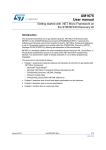
• GPIO(Pin) output speed configuration
• Change the rising and falling edge when pin change state from high to low or low to high
• Higher GPIO speed increase EMI noise from STM32 and increase STM32 consumption
• It is good to adapt GPIO speed with periphery speed. Ex.: Toggling GPIO on 1Hz is LOW
optimal settings, but SPI on 45MHz the HIGH must be set
GPIO output LOW speed
GPIO output MEDIUM speed
LOW
LOW
HIGH
HIGH
GPIO output HIGH speed
GPIO output FAST speed
LOW
LOW
HIGH
HIGH
40
1
Configure GPIO for LED toggling
• Now we set the project details for generation
• Menu > Project > Project Settings
• Set the project name
• Project location
• Type of toolchain
• Now we can Generate Code
• Menu > Project > Generate Code
41
1
Configure GPIO for LED toggling
• Now we open the project in our IDE
• The functions we want to put into main.c
• Between /* USER CODE BEGIN 3 */ and /* USER CODE END 3 */ tags
• Into infinite loop while(1){ }
• For toggling we need to use this functions
• HAL_HAL_Delay which create specific delay
• HAL_GPIO_WritePin or HAL_GPIO_TogglePin
42
1
Configure GPIO for LED toggling
• Now we open the project in our IDE
• The functions we want to put into main.c
• Between /* USER CODE BEGIN 3 */ and /* USER CODE END 3 */ tags
• Into infinite loop while(1){ }
• For toggling we need to use this functions
• HAL_HAL_Delay which create specific delay
• HAL_GPIO_WritePin or HAL_GPIO_TogglePin
/* USER CODE BEGIN 3 */
/* Infinite loop */
while (1)
{
HAL_GPIO_WritePin(GPIOG, GPIO_PIN_14, GPIO_PIN_SET);
HAL_Delay(500);
HAL_GPIO_WritePin(GPIOG, GPIO_PIN_14, GPIO_PIN_RESET);
HAL_Delay(500);
}
/* USER CODE END 3 */
43
EXTI lab 2
STM32F42xx Technical Training
20/10/2015
2
Configure EXTI which turns on LED
• Objective
• Learn how to setup input pin with EXTI in CubeMX
• How to Generate Code in CubeMX and use HAL functions
• Goal
• Configure GPIO and EXTI pin in CubeMX and Generate Code
• Add into project Callback function and function which turn on led
• Verify the correct functionality by pressing button which turns on LED
45
2
Configure EXTI which turns on LED
• Create project in CubeMX
• Menu > File > New Project
• Select STM32F4 > STM32F429/439 > LQFP144 > STM32F439ZITx
• Configure LED pin as GPIO_Output
• Configure Button pin as GPIO_EXTIX
46
2
Configure EXTI which turns on LED
• Create project in CubeMX
• Menu > File > New Project
• Select STM32F4 > STM32F429/439 > LQFP144 > STM32F439ZITx
• Configure LED pin as GPIO_Output
• Configure Button pin as GPIO_EXTIX
47
2
Configure EXTI which turns on LED
• In order to run on maximum frequency, setup clock system
• Details in lab 0
48
2
Configure EXTI which turns on LED
• GPIO Configuration
• TAB>Configuration>System>GPIO
49
2
Configure EXTI which turns on LED
• GPIO(Pin) Configuration
• Select External Interrupt Mode with Rising edge trigger detection
• No pull-up or pull-down
• PG14 can be let in default
settings
• Button OK
50
2
Configure EXTI which turns on LED
• NVIC Configuration
• We need to enable interrupts for EXTI
• TAB>Configuration>System>NVIC
51
2
Configure EXTI which turns on LED
• NVIC Configuration
• Enable interrupt for
EXTI Line0
• Button OK
52
2
Configure EXTI which turns on LED
• Now we set the project details for generation
• Menu > Project > Project Settings
• Set the project name
• Project location
• Type of toolchain
• Now we can Generate Code
• Menu > Project > Generate Code
53
2
Configure EXTI which turns on LED
54
HAL Library work flow 1
Peripheral Initializations
including peripheral interrupt NVIC
initializations
Generated by
CubeMX
Configure the GPIO to generate interrupt on
rising or falling edge
HAL_EXTI0_IRQHandler
Edge detection callback
HAL_GPIO_EXTI_Callback
EXTI0_IRQHandler
2
Configure EXTI which turns on LED
55
HAL Library work flow 2
Peripheral Initializations
including peripheral interrupt NVIC
initializations
MX_GPIO_Init
inside main.c
Configure the GPIO to generate interrupt on
rising or falling edge
HAL_EXTI0_IRQHandler
Edge detection callback
HAL_GPIO_EXTI_Callback
EXTI0_IRQHandler
2
Configure EXTI which turns on LED
56
HAL Library working flow 3
Peripheral Initializations
including peripheral interrupt NVIC
initializations
inside
stm32f4xx_it.c
Configure the GPIO to generate interrupt on
rising or falling edge
HAL_EXTI0_IRQHandler
Edge detection callback
HAL_GPIO_EXTI_Callback
EXTI0_IRQHandler
2
Configure EXTI which turns on LED
57
HAL Library work flow 4
Peripheral Initializations
including peripheral interrupt NVIC
initializations
Configure the GPIO to generate interrupt on
rising or falling edge
HAL_EXTI0_IRQHandler
EXTI0_IRQHandler
Edge detection callback
HAL_GPIO_EXTI_Callback
User must define Callback
it is declared by default as
empty weak
2
Configure EXTI which turns on LED
58
HAL Library work flow 5
Peripheral Initializations
including peripheral interrupt NVIC
initializations
Configure the GPIO to generate interrupt on
rising or falling edge
HAL_EXTI0_IRQHandler
EXTI0_IRQHandler
Edge detection callback
HAL_GPIO_EXTI_Callback
Usually in main.c between
/* USER CODE BEGIN */
tags
2
Configure EXTI which turns on LED
HAL Library work flow summary
59
3. create
edge
1. init NVIC
Peripheral Initializations
including peripheral interrupt NVIC
initializations
2. init GPIO
Configure the GPIO to generate interrupt on
rising or falling edge
5. HAL EXTI
interrupt handler
HAL_EXTI0_IRQHandler
Edge detection callback
HAL_GPIO_EXTI_Callback
6. HAL EXTI
callback
HAL files clearing
flags, check errors,
…
4. EXTI interrupt
handler
EXTI0_IRQHandler
2
Configure EXTI which turns on LED
• Now we open the project in our IDE
• The functions we want to put into main.c
• Between /* USER CODE BEGIN 4 */ and /* USER CODE END 4 */ tags
• We create function which will handle the EXTI interrupts
• The HAL callback function for EXTI
• void HAL_GPIO_EXTI_Callback(uint16_t GPIO_Pin)
• For LED turn on we need to use this functions
• HAL_GPIO_WritePin
60
2
Configure EXTI which turns on LED
• Now we open the project in our IDE
• The functions we want to put into main.c
• Between /* USER CODE BEGIN 4 */ and /* USER CODE END 4 */ tags
• We create function which will handle the EXTI interrupts
• The HAL callback function for EXTI
• void HAL_GPIO_EXTI_Callback(uint16_t GPIO_Pin)
• For LED turn on we need to use this functions
• HAL_GPIO_WritePin
/* USER CODE BEGIN 4 */
void HAL_GPIO_EXTI_Callback(uint16_t GPIO_Pin)
{
if(GPIO_Pin == GPIO_PIN_0) {
HAL_GPIO_WritePin(GPIOG, GPIO_PIN_14, GPIO_PIN_SET);
} else {
__NOP();
}
}
/* USER CODE END 4 */
61
Low Power mode SLEEP lab 3
STM32F42xx Technical Training
20/10/2015
3
Use SLEEP mode with EXTI
• Objective
• We use the EXTI setup from lab 1
• Learn how to setup SLEEP in HAL
• Create simple project with SLEEP mode with wake up on pin press
• Goal
• Use project from EXTI lab
• Learn how to setup the SLEEP in HAL, which events can wake up you
• Verify the correct functionality by measuring consumption
63
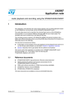
SLEEP Mode
GPIO’s
Core
CM4
RTC/backup reg.
RAM
IWDG
DMA
GP timers
Clock
HSI
SPI
USB
HSE
LSI
LSE
DAC
ADC
FLASH
USART
I2C
Reset
Power
regulator
• Core is stopped
• Peripherals are running
3
Use SLEEP mode with EXTI
HAL Library work flow summary
65
4. create
edge
1. init NVIC
Peripheral Initializations
including peripheral interrupt NVIC
initializations
2. init GPIO
Configure the GPIO to generate interrupt on
rising or falling edge
5. EXTI interrupt
handler
3. Use WFI
Enter into SLEEP mode(WFI)
HAL_EXTI0_IRQHandler
6. HAL EXTI
interrupt handler
Edge detection callback
HAL_GPIO_EXTI_Callback
7. HAL EXTI
callback
HAL files clearing
flags, check errors,
…
EXTI0_IRQHandler
3
Use SLEEP mode with EXTI
• Now we open the project in our IDE
• The functions we want to put into main.c
• Between /* USER CODE BEGIN 3 */ and /* USER CODE END 3 */ tags
• Function to enter SLEEP
• HAL_PWR_EnterSLEEPMode(uint32_t Regulator, uint8_t SLEEPEntry)
• We can measure consumption
To be able to reprogram
the STM32 which is in
LP mode, use
connection during
reset option
66
3
Use SLEEP mode with EXTI
• Now we open the project in our IDE
• The functions we want to put into main.c
• Between /* USER CODE BEGIN 3 */ and /* USER CODE END 3 */ tags
• Function to enter SLEEP
• HAL_PWR_EnterSLEEPMode(uint32_t Regulator, uint8_t SLEEPEntry)
• We can measure consumption
/* USER CODE BEGIN 3 */
/* Infinite loop */
while (1)
{
HAL_Delay(1000);
HAL_PWR_EnterSLEEPMode(PWR_LOWPOWERREGULATOR_ON,PWR_SLEEPENTRY_WFI);
}
/* USER CODE END 3 */
67
3
Use SLEEP mode with EXTI
• Consumption still to high?
• Is STM32 really in SLEEP?
• Is the Systick disabled?
/* USER CODE BEGIN 3 */
/* Infinite loop */
while (1)
{
HAL_Delay(1000);
HAL_SuspendTick();
HAL_PWR_EnterSLEEPMode(PWR_LOWPOWERREGULATOR_ON,PWR_SLEEPENTRY_WFI);
HAL_ResumeTick();
}
/* USER CODE END 3 */
• Is this better?
68
Low Power mode STOP lab 4
STM32F42xx Technical Training
20/10/2015
4
Use STOP mode with EXTI
• Objective
• We use the EXTI setup from lab 1
• Learn how to setup STOP in HAL
• Create simple project with STOP mode with wake up on pin press
• Goal
• Use project from EXTI lab
• Learn how to setup the STOP in HAL, which events can wake up you
• Verify the correct functionality by measuring consumption
70
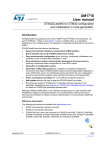
STOP Mode
• Core is stopped
GPIO’s
Core
CM4
RTC/backup reg.
IWDG
GP timers
FLASH
RAM
DMA
DAC
ADC
• SRAM and registers
content is preserved
• Peripherals with HSI, LSI,
LSE clock option can be
ON
Clock
HSE
HSI
SPI
USB
• HSE, MSI clocks are OFF
• GPIO’s keep their setup
LSI
LSE
Reset
Power
regulator
USART
I2C
4
Use STOP mode with EXTI
HAL Library work flow summary
72
4. create
edge
1. init NVIC
Peripheral Initializations
including peripheral interrupt NVIC
initializations
2. init GPIO
Configure the GPIO to generate interrupt on
rising or falling edge
Enter into STOP mode(WFI)
Clock reconfigure
Edge detection callback
HAL_GPIO_EXTI_Callback
7. HAL EXTI
callback
5. EXTI interrupt
handler
3. Use WFI
HAL_EXTI0_IRQHandler
8. Reconfigure
clock after
wakeup
6. HAL EXTI
interrupt handler
HAL files clearing
flags, check errors,
…
EXTI0_IRQHandler
4
Use STOP mode with EXTI
• Now we open the project in our IDE
• The functions we want to put into main.c
• Between /* USER CODE BEGIN 3 */ and /* USER CODE END 3 */ tags
• Function to enter SLEEP
• HAL_PWR_EnterSTOPMode(uint32_t Regulator, uint8_t STOPEntry)
• HAL_PWREx_EnterUnderDriveSTOPMode(uint32_t Regulator, uint8_t STOPEntry)
• We can measure consumption
To be able to reprogram
the STM32 which is in
LP mode, use
connection during
reset option
73
4
Use STOP mode with EXTI
74
• Now we open the project in our IDE
• The functions we want to put into main.c
• Between /* USER CODE BEGIN 3 */ and /* USER CODE END 3 */ tags
• Function to enter SLEEP
• HAL_PWR_EnterSTOPMode(uint32_t Regulator, uint8_t STOPEntry)
• HAL_PWREx_EnterUnderDriveSTOPMode(uint32_t Regulator, uint8_t STOPEntry)
• We can measure consumption
/* USER CODE BEGIN 3 */
/* Infinite loop */
while (1)
{
HAL_Delay(1000);
HAL_PWR_EnterSTOPMode(PWR_LOWPOWERREGULATOR_ON,PWR_STOPENTRY_WFI);
SystemClock_Config();
}
/* USER CODE END 3 */
4
Use STOP mode with EXTI
• Or different function
/* USER CODE BEGIN 3 */
/* Infinite loop */
while (1)
{
HAL_Delay(1000);
HAL_PWREx_EnterUnderDriveSTOPMode(PWR_LOWPOWERREGULATOR_UNDERDRIVE_ON,PWR_STOPENTRY_WFI);
SystemClock_Config();
}
/* USER CODE END 3 */
75
Low Power mode STANDBY lab 5
STM32F42xx Technical Training
20/10/2015
5
Use STANDBY mode
• Objective
• For this lab create empty CubeMX project
• Learn how to setup STANDBY in HAL
• Create simple project with STANDBY mode with wake up on pin press
• Goal
• Learn how to setup the STANDBY in HAL, which events can wake up you
• Verify the correct functionality by measuring consumption
77
STANDBY Mode
GPIO’s
Core
CM4
RTC/backup reg.
FLASH
RAM
IWDG
DMA
GP timers
Clock
HSE
• Core and all peripherals
are OFF, except RTC and
IWDG if enabled
• HSE, MSI, HSI clocks are
OFF, LSI LSE can be ON
• SRAM and registers
content is lost, except
RTC, and standby circuitry
SPI
HSI
USB
LSI
LSE
DAC
USART
I2C
Reset
ADC
Power
regulator
Reset
RTC OUT
WKUP 1,2,3
• GPIO’s are in high Z,
except Reset, RTC OUT
and WKUP 1,2,3
5
Use STANDBY mode
HAL Library work flow summary
1. init NVIC
Peripheral Initializations
including peripheral interrupt NVIC
initializations
2. Standby
Enable Wake-up pin
Enter into STANDBY mode(WFI)
Reset
3. Use WFI
5. Wake up
STM with reset
4. create
edge
79
5
Use STANDBY mode
• Now we open the project in our IDE
• The functions we want to put into main.c
• Between /* USER CODE BEGIN 3 */ and /* USER CODE END 3 */ tags
• For Wake up we need to setup wake up pin
• HAL_PWR_EnableWakeUpPin(uint32_t WakeUpPinx)
• Function to enter STANDBY
• HAL_PWR_EnterSTANDBYMode();
• We can measure consumption
To be able to reprogram
the STM32 which is in
LP mode, use
connection during
reset option
80
5
Use STANDBY mode
• Now we open the project in our IDE
• The functions we want to put into main.c
• Between /* USER CODE BEGIN 3 */ and /* USER CODE END 3 */ tags
• Function to enter SLEEP
• HAL_PWR_EnterSTOPMode(uint32_t Regulator, uint8_t STOPEntry)
• HAL_PWREx_EnterUnderDriveSTOPMode(uint32_t Regulator, uint8_t STOPEntry)
• We can measure consumption
/* USER CODE BEGIN 3 */
/* Infinite loop */
while (1)
{
HAL_GPIO_TogglePin(GPIOG, GPIO_PIN_14);
HAL_Delay(2000);
HAL_PWR_EnableWakeUpPin(PWR_WAKEUP_PIN1);
HAL_PWR_EnterSTANDBYMode();
}
/* USER CODE END 3 */
81
5
Use STANDBY mode
• We cannot go into STANDBY again?
• Try to clear wake up flag
• __HAL_PWR_CLEAR_FLAG(PWR_FLAG_WU);
/* USER CODE BEGIN 2 */
__HAL_PWR_CLEAR_FLAG(PWR_FLAG_WU);
/* USER CODE END 2 */
82
Data transfer over DMA lab 6
STM32F42xx Technical Training
20/10/2015
6
Use DMA in M2M transfer
• Objective
• Learn how to setup DMA transfer in CubeMX
• Create simple DMA memory to memory transfer from RAM to RAM
• Goal
• Use CubeMX and Generate Code with DMA
• Learn how to setup the DMA in HAL
• Verify the correct functionality by comparing transferred buffers
84
6
CORTEX-M4
168MHz
w/ FPU & MPU
Ethernet
10/100
High Speed
USB2.0
Dual Port
DMA1
Dual Port
DMA2
Master 5
Master 4
Master 2
Master 3
FIFO/DMA
FIFO/DMA
FIFO/8 Streams
FIFO/8 Streams
85
Dual Port
AHB1-APB2
S-Bus
I-Bus
Master 1
AHB1
Dual Port
AHB1-APB1
AHB2
SRAM1
112KB
SRAM2
16KB
FSMC
I-Code
D-Code
Multi-AHB Bus Matrix
ART
Accelerator
D-Bus
CCM
data RAM
64KB
Use DMA in M2M transfer
FLASH
1Mbytes
6
Use DMA in M2M transfer
• Create project in CubeMX
• Menu > File > New Project
• Select STM32F4 > STM32F429/439 > LQFP144 > STM32F439ZITx
• For DMA we don’t need to configure any pins
86
6
Use DMA in M2M transfer
• In order to run on maximum frequency, setup clock system
• Details in lab 0
87
6
Use DMA in M2M transfer
• DMA configuration
• TAB>Configuration
• System>DMA
• TAB>DMA2
• Button ADD
1. TAB >
Configuration
3. TAB>DMA 2
4. Add DMA
channel
2. System DMA
88
6
Use DMA in M2M transfer
• DMA configuration
• Select MEMTOMEM
DMA request
1. MEMTOMEM
• Normal mode
• Increment source and
destination address
• FIFO setup
• Byte data width
• Burst size
• Button OK
3. Increment
addresses
5. Data width and
Burst
2. Normal
mode
4. FIFO setup
6. OK
89
6
Use DMA in M2M transfer
• Now we set the project details for generation
• Menu > Project > Project Settings
• Set the project name
• Project location
• Type of toolchain
• Now we can Generate Code
• Menu > Project > Generate Code
90
6
Use DMA in M2M transfer
• Start process DMA (same for TIM, ADC)
• Non blocking start process
• The end of the process must be checked by polling
1. init DMA
Peripheral
Initializations
Start Process
(HAL_DMA_Start)
2. Start DMA
3. DMA transfer data
Poll for process complete
(HAL_DMA_PollForTransfer)
4. Check if transfer is complete
91
6
Use DMA in M2M transfer
• Return values
• Most of CubeMX functions have return values, which indicate, if operation was successful,
timeout occurs of function end with error
• Is recommended handle this return values to be sure that program working as expected
Ex: Poll for process complete
(HAL_DMA_PollForTransfer)
HAL_OK
DMA transfer was successfully
finished and data was
transferred to destination
without error
HAL_ERROR
HAL_BUSY
92
6
Use DMA in M2M transfer
• Return values
• Most of CubeMX functions have return values, which indicate, if operation was successful,
timeout occurs of function end with error
• Is recommended handle this return values to be sure that program working as expected
Ex: Poll for process complete
(HAL_DMA_PollForTransfer)
HAL_OK
HAL_ERROR
HAL_BUSY
Error occurs during DMA
transfer you use
HAL_DMA_GetError for
details what happened
93
6
Use DMA in M2M transfer
• Return values
• Most of CubeMX functions have return values, which indicate, if operation was successful,
timeout occurs of function end with error
• Is recommended handle this return values to be sure that program working as expected
Ex: Poll for process complete
(HAL_DMA_PollForTransfer)
HAL_OK
HAL_ERROR
HAL_BUSY
DMA transfer in progress,
user can only abort the
transfer
94
6
Use DMA in M2M transfer
• Now we open the project in our IDE
• The functions we want to put into main.c
• Between /* USER CODE BEGIN 2 */ and /* USER CODE END 2 */ tags
• HAL functions for DMA
• HAL_DMA_Start(DMA_HandleTypeDef *hdma, uint32_t SrcAddress, uint32_t DstAddress,
uint32_t DataLength)
• HAL_DMA_PollForTransfer(DMA_HandleTypeDef *hdma, uint32_t CompleteLevel, uint32_t
Timeout)
95
6
Use DMA in M2M transfer
• We create two buffers
• One with source data
• Second as destination buffer
/* USER
uint8_t
uint8_t
/* USER
CODE BEGIN 0 */
Buffer_Src[]={0,1,2,3,4,5,6,7,8,9};
Buffer_Dest[10];
CODE END 0 */
96
6
Use DMA in M2M transfer
• HAL_DMA_Start start the M2M data transfer
• HAL_DMA_PollForTransfer check if the transfer ends successfully
/* USER CODE BEGIN 2 */
HAL_DMA_Start(&hdma_memtomem_dma2_stream0, (uint32_t) (Buffer_Src), (uint32_t) (Buffer_Dest), 10);
while(HAL_DMA_PollForTransfer(&hdma_memtomem_dma2_stream0, HAL_DMA_FULL_TRANSFER, 100) != HAL_OK)
{
__NOP();
}
/* USER CODE END 2 */
97
Data transfer over DMA with interrupt
lab 7
STM32F42xx Technical Training
20/10/2015
7
Use DMA M2M transfer with interrupt
• Objective
• Learn how to setup DMA transfer with interrupt in CubeMX
• Create simple DMA memory to memory transfer from RAM to RAM
• Goal
• Use CubeMX and Generate Code with DMA
• Learn how to setup the DMA in HAL
• Verify the correct functionality by comparing transferred buffers
99
7
Use DMA M2M transfer with interrupt
• Create project in CubeMX
• Menu > File > New Project
• Select STM32F4 > STM32F429/439 > LQFP144 > STM32F439ZITx
• For DMA we don’t need to configure any pins
100
7
Use DMA M2M transfer with interrupt
• In order to run on maximum frequency, setup clock system
• Details in lab 0
101
7
Use DMA M2M transfer with interrupt
• DMA configuration
• TAB>Configuration
• System>DMA
• TAB>DMA2
• Button ADD
1. TAB >
Configuration
3. TAB>DMA 2
4. Add DMA
channel
2. System DMA
102
7
Use DMA M2M transfer with interrupt
• DMA configuration
• Select MEMTOMEM
DMA request
1. MEMTOMEM
• Normal mode
• Increment source and
destination address
• FIFO setup
• Byte data width
• Burst size
• Button OK
3. Increment
addresses
5. Data width and
Burst
2. Normal
mode
4. FIFO setup
6. OK
103
7
Use DMA M2M transfer with interrupt
• DMA configuration
1. TAB >
Configuration
• System > NVIC
• Enable DMA2 Stream interrupt
• Button OK
2. System > NVIC
3. Enable DMA2
interrupts
4. OK
104
7
Use DMA M2M transfer with interrupt
• Now we set the project details for generation
• Menu > Project > Project Settings
• Set the project name
• Project location
• Type of toolchain
• Now we can Generate Code
• Menu > Project > Generate Code
105
7
Use DMA M2M transfer with interrupt
106
HAL Library DMA with IT flow
DMA Initializations
including peripheral interrupt NVIC
initializations
Start process with interrupt generation at end
of process
HAL_DMA_Start_IT
HAL_OK
HAL_ERROR
end of process callback
DMA_XferCpltCallback
process Error callback
DMA_XferErrorCallback
HAL_BUSY
HAL_DMA_IRQHandler
DMA2_Stream0_IRQHandler
7
Use DMA M2M transfer with interrupt
107
HAL Library DMA with IT flow
DMA Initializations
including peripheral interrupt NVIC
initializations
Generated by CubeMX
Start process with interrupt generation at end
of process
HAL_DMA_Start_IT
HAL_OK
HAL_ERROR
end of process callback
DMA_XferCpltCallback
process Error callback
DMA_XferErrorCallback
HAL_BUSY
HAL_DMA_IRQHandler
DMA2_Stream0_IRQHandler
7
Use DMA M2M transfer with interrupt
108
HAL Library DMA with IT flow
DMA Initializations
including peripheral interrupt NVIC
initializations
Start process with interrupt generation at end
of process
HAL_DMA_Start_IT
HAL_OK
HAL_ERROR
HAL_BUSY
HAL_DMA_IRQHandler
DMA2_Stream0_IRQHandler
end of process callback
DMA_XferCpltCallback
process Error callback
DMA_XferErrorCallback
Defined by user
7
Use DMA M2M transfer with interrupt
109
HAL Library DMA with IT flow
DMA Initializations
including peripheral interrupt NVIC
initializations
Generated in main.c
Start process with interrupt generation at end
of process
HAL_DMA_Start_IT
HAL_OK
HAL_ERROR
end of process callback
DMA_XferCpltCallback
process Error callback
DMA_XferErrorCallback
HAL_BUSY
HAL_DMA_IRQHandler
DMA2_Stream0_IRQHandler
7
Use DMA M2M transfer with interrupt
110
HAL Library DMA with IT flow
DMA Initializations
including peripheral interrupt NVIC
initializations
Start process with interrupt generation at end
of process
HAL_DMA_Start_IT
HAL_OK
HAL_ERROR
end of process callback
DMA_XferCpltCallback
process Error callback
DMA_XferErrorCallback
HAL_BUSY
HAL_DMA_IRQHandler
DMA2_Stream0_IRQHandler
We recommend to use it
in main.c
7
Use DMA M2M transfer with interrupt
111
HAL Library DMA with IT flow
DMA Initializations
including peripheral interrupt NVIC
initializations
Start process with interrupt generation at end
of process
HAL_DMA_Start_IT
HAL_OK
HAL_ERROR
HAL_BUSY
HAL_DMA_IRQHandler
DMA2_Stream0_IRQHandler
end of process callback
DMA_XferCpltCallback
process Error callback
DMA_XferErrorCallback
User defined functions. The
user must define functions by
himself and put function names
into DMA structure
7
Use DMA M2M transfer with interrupt
112
HAL Library DMA with IT flow
DMA Initializations
including peripheral interrupt NVIC
initializations
Start process with interrupt generation at end
of process
HAL_DMA_Start_IT
HAL_OK
HAL_ERROR
end of process callback
DMA_XferCpltCallback
process Error callback
DMA_XferErrorCallback
HAL_BUSY
HAL_DMA_IRQHandler
DMA2_Stream0_IRQHandler
Generated in
stm32f4xx_it.c
7
Use DMA M2M transfer with interrupt
113
HAL Library DMA with IT flow
DMA Initializations
including peripheral interrupt NVIC
initializations
Start process with interrupt generation at end
of process
HAL_DMA_Start_IT
HAL_OK
HAL_ERROR
end of process callback
DMA_XferCpltCallback
process Error callback
DMA_XferErrorCallback
HAL_BUSY
HAL_DMA_IRQHandler
DMA2_Stream0_IRQHandler
Defined in
stm32f4xx_hal_dma.c
7
Use DMA M2M transfer with interrupt
114
HAL Library DMA with IT flow
DMA Initializations
including peripheral interrupt NVIC
initializations
Start process with interrupt generation at end
of process
HAL_DMA_Start_IT
HAL_OK
HAL_ERROR
end of process callback
DMA_XferCpltCallback
process Error callback
DMA_XferErrorCallback
HAL_BUSY
Start DMA buffer transfer
Not blocking function
program can continue
HAL_DMA_IRQHandler
DMA2_Stream0_IRQHandler
7
Use DMA M2M transfer with interrupt
115
HAL Library DMA with IT flow
Interrupt indicate DMA
process is half/complete
or error was detected
DMA Initializations
including peripheral interrupt NVIC
initializations
Start process with interrupt generation at end
of process
HAL_DMA_Start_IT
HAL_OK
HAL_ERROR
end of process callback
DMA_XferCpltCallback
process Error callback
DMA_XferErrorCallback
HAL_BUSY
HAL_DMA_IRQHandler
DMA2_Stream0_IRQHandler
7
Use DMA M2M transfer with interrupt
116
HAL Library DMA with IT flow
DMA Initializations
including peripheral interrupt NVIC
initializations
Process interrupt
information
Start process with interrupt generation at end
of process
HAL_DMA_Start_IT
HAL_OK
HAL_ERROR
end of process callback
DMA_XferCpltCallback
process Error callback
DMA_XferErrorCallback
HAL_BUSY
HAL_DMA_IRQHandler
DMA2_Stream0_IRQHandler
7
Use DMA M2M transfer with interrupt
117
HAL Library DMA with IT flow
DMA Initializations
including peripheral interrupt NVIC
initializations
Start process with interrupt generation at end
of process
HAL_DMA_Start_IT
HAL_OK
HAL_ERROR
end of process callback
DMA_XferCpltCallback
process Error callback
DMA_XferErrorCallback
HAL_BUSY
HAL_DMA_IRQHandler
DMA2_Stream0_IRQHandler
Data correctly transferred
Complete callback
function
7
Use DMA M2M transfer with interrupt
118
HAL Library DMA with IT flow
DMA Initializations
including peripheral interrupt NVIC
initializations
Start process with interrupt generation at end
of process
HAL_DMA_Start_IT
HAL_OK
HAL_ERROR
end of process callback
DMA_XferCpltCallback
process Error callback
DMA_XferErrorCallback
HAL_BUSY
HAL_DMA_IRQHandler
DMA2_Stream0_IRQHandler
Error was detected
Error callback function
7
Use DMA M2M transfer with interrupt
119
HAL Library DMA with IT flow
1. DMA init
DMA Initializations
including peripheral interrupt NVIC
initializations
Start process with interrupt generation at end
of process
HAL_DMA_Start_IT
HAL_OK
HAL_ERROR
2. DMA transfer
start
HAL_BUSY
end of process callback
DMA_XferCpltCallback
5. DMA transfer
was correct
process Error callback
DMA_XferErrorCallback
5. Error in DMA
transfer
HAL_DMA_IRQHandler
4. HAL DMA
management
DMA2_Stream0_IRQHandler
3. DMA transfer
complete or error
7
Use DMA M2M transfer with interrupt
• Now we open the project in our IDE
• The functions we want to put into main.c
• Between /* USER CODE BEGIN 2 */ and /* USER CODE END 2 */ tags
• DMA callback function
• We need to add the name of callback function into DMA structure
• HAL functions for DMA
• HAL_DMA_Start_IT(DMA_HandleTypeDef *hdma, uint32_t SrcAddress, uint32_t DstAddress,
uint32_t DataLength)
120
7
Use DMA M2M transfer with interrupt
• We create two buffers
• One with source data
• Second as destination buffer
/* USER
uint8_t
uint8_t
/* USER
CODE BEGIN 0 */
Buffer_Src[]={0,1,2,3,4,5,6,7,8,9};
Buffer_Dest[10];
CODE END 0 */
121
7
Use DMA M2M transfer with interrupt
• DMA callback creation function prototype
/* USER CODE BEGIN 0 */
uint8_t Buffer_Src[]={0,1,2,3,4,5,6,7,8,9};
uint8_t Buffer_Dest[10];
void XferCpltCallback(DMA_HandleTypeDef *hdma);
/* USER CODE END 0 */
• DMA complete callback with nop where we can put breakpoint
/* USER CODE BEGIN 4 */
void XferCpltCallback(DMA_HandleTypeDef *hdma)
{
__NOP();//we reach this only if DMA transfer was correct
}
/* USER CODE END 4 */
122
7
Use DMA M2M transfer with interrupt
123
• DMA Start
• Before we start the DMA with interrupt we need to set the callback into DMA structure
• Then is possible use the HAL_DMA_Start_IT to begin DMA transfer
/* USER CODE BEGIN 2 */
hdma_memtomem_dma2_stream0.XferCpltCallback=&XferCpltCallback;
HAL_DMA_Start_IT(&hdma_memtomem_dma2_stream0,(uint32_t)Buffer_Src,(uint32_t)Buffer_Dest,10);
/* USER CODE END 2 */
Use RTC Alarm lab 8
STM32F42xx Technical Training
20/10/2015
8
Use RTC and Alarm with interrupt
• Objective
• Learn how to setup RTC with interrupt in CubeMX
• Create simple RTC project with periodic alarm interrupt
• Goal
• Use CubeMX and Generate Code with RTC
• Learn how to setup the RTC in HAL
• Verify the correct functionality by periodic RTC alarm interrupts
125
8
Use RTC and Alarm with interrupt
• Create project in CubeMX
• Menu > File > New Project
• Select STM32F4 > STM32F429/439 > LQFP144 > STM32F439ZITx
• Set Internal Alarm on Alarm A or Alarm B
• Set GPIO to toggle with LED as alarm indication
126
8
Use RTC and Alarm with interrupt
• In order to run on maximum frequency, setup clock system
• Details in lab 0
127
8
Use RTC and Alarm with interrupt
• RTC Configuration
• TAB>Configuration
1. TAB > Configuration
• Control > RTC
• Set parameters which you want
2. RTC
3. Check configuration
128
8
Use RTC and Alarm with interrupt
• RTC Configuration NVIC
129
1. TAB > NVIC
• TAB>NVIC Setup
• Enable Alarm interrupt
• Button OK
2. Enable RTC Alarm
3. Button OK
8
Use RTC and Alarm with interrupt
• Now we set the project details for generation
• Menu > Project > Project Settings
• Set the project name
• Project location
• Type of toolchain
• Now we can Generate Code
• Menu > Project > Generate Code
130
8
Use RTC and Alarm with interrupt
• The RTC can be preserved during RESET(ok LP modes)
• CubeMX not enable the RTC by default
• We need to add HAL_PWR_EnableBkUpAccess() and __HAL_RCC_RTC_ENABLE() before
we call MX_RTC_Init()
• Set the first alarm to 1s
• In MX_RTC_Init
• We create the RTC interrupt handler and we reconfigure the Alarm A time
• HAL_RTC_AlarmAEventCallback(RTC_HandleTypeDef *hrtc)
• HAL_RTC_GetAlarm(RTC_HandleTypeDef *hrtc, RTC_AlarmTypeDef *sAlarm, uint32_t Alarm,
uint32_t Format)
• HAL_RTC_SetAlarm_IT(RTC_HandleTypeDef *hrtc, RTC_AlarmTypeDef *sAlarm, uint32_t
Format)
• RTC alarm indication will be done by LED
• HAL_GPIO_TogglePin(GPIO_TypeDef* GPIOx, uint16_t GPIO_Pin)
131
8
Use RTC and Alarm with interrupt
• RTC enable
/* Initialize all configured peripherals */
HAL_PWR_EnableBkUpAccess();//enable PWR backup domain access (RTC,BKReg)
__HAL_RCC_RTC_ENABLE();//Enable RTC. not created by cube because the RTC can run.
MX_GPIO_Init();
MX_RTC_Init();
• In MX_RTC_Init we set first Alarm to 1s
/**Enable the Alarm A
*/
sAlarm.AlarmTime.Hours = 0;
sAlarm.AlarmTime.Minutes = 0;
sAlarm.AlarmTime.Seconds = 1;
sAlarm.AlarmTime.SubSeconds = 0;
132
8
Use RTC and Alarm with interrupt
• RTC enable
/* USER CODE BEGIN 4 */
void HAL_RTC_AlarmAEventCallback(RTC_HandleTypeDef *hrtc){
RTC_AlarmTypeDef sAlarm;
HAL_RTC_GetAlarm(hrtc,&sAlarm,RTC_ALARM_A,FORMAT_BIN);
if(sAlarm.AlarmTime.Seconds>58){
sAlarm.AlarmTime.Seconds=0;
}else{
sAlarm.AlarmTime.Seconds=sAlarm.AlarmTime.Seconds+1;
}
while(HAL_RTC_SetAlarm_IT(hrtc, &sAlarm, FORMAT_BIN)!=HAL_OK){}
HAL_GPIO_TogglePin(GPIOG,GPIO_PIN_14);
}
/* USER CODE END 4 */
133
8
Use RTC and Alarm with interrupt
134
• Advanced task
• The counting stops after 1minute
• Modify the project to create alarm every 1s for infinite time
/**Enable the Alarm A
*/
sAlarm.AlarmTime.Hours = 0;
sAlarm.AlarmTime.Minutes = 0;
sAlarm.AlarmTime.Seconds = 1;
sAlarm.AlarmTime.SubSeconds = 0;
sAlarm.AlarmTime.TimeFormat = RTC_HOURFORMAT12_AM;
sAlarm.AlarmTime.DayLightSaving = RTC_DAYLIGHTSAVING_NONE;
sAlarm.AlarmTime.StoreOperation = RTC_STOREOPERATION_RESET;
sAlarm.AlarmMask = RTC_ALARMMASK_DATEWEEKDAY|RTC_ALARMMASK_HOURS|RTC_ALARMMASK_MINUTES;
sAlarm.AlarmSubSecondMask = RTC_ALARMSUBSECONDMASK_ALL;
sAlarm.AlarmDateWeekDaySel = RTC_ALARMDATEWEEKDAYSEL_DATE;
sAlarm.AlarmDateWeekDay = 1;
sAlarm.Alarm = RTC_ALARM_A;
HAL_RTC_SetAlarm_IT(&hrtc, &sAlarm, FORMAT_BCD);
• We only need to modify the Alarm mask to ignore Days, Hours and Minutes
UART Poll lab 9
STM32F42xx Technical Training
20/10/2015
9
Simple UART communication
• Objective
• Learn how to setup UART in CubeMX
• How to Generate Code in CubeMX and use HAL functions
• Work in pairs, one will create transmitter and second receiver
• Goal
• Configure UART in CubeMX and Generate Code
• Learn how to send and receive data over UART without interrupts
• Verify the correct functionality
136
9
Simple UART communication
• Create project in CubeMX
• Menu > File > New Project
• Select STM32F4 > STM32F429/439 > LQFP144 > STM32F439ZITx
• Pin selection
• We are looking for free pins where is possible to create wire loopback connection
137
9
Simple UART communication
• Pin selection
• We are looking for free pins
where is possible to create
wire loopback connection
Image from
STM32F429-Discovery
user manual
138
9
Simple UART communication
• Pin selection
• We are looking for free pins where is possible to create wire loopback connection
Image from
STM32F429
datasheet
139
9
Simple UART communication
• Hardware preparation
• We connect selected pins together by jumper, this help us to create loopback on UART
Hardware
connection
RX <-TX
TX>RX
140
9
Simple UART communication
• Create project in CubeMX
• Menu > File > New Project
• Select STM32F4 > STM32F429/439 > LQFP144 > STM32F439ZITx
• CubeMX UART selection
• Select USART1 in asynchronous mode
• Select PA9 and PA10 for USART1 if weren't selected
141
9
Simple UART communication
• In order to run on maximum frequency, setup clock system
• Details in lab 0
142
9
Simple UART communication
• CubeMX UART configuration
• Tab>Configuration>Connectivity>USART1
143
9
Simple UART communication
• CubeMX USART configuration check:
• BaudRate
• World length
• Parity
• Stop bits
• Data direction
• Oversampling
144
9
Simple UART communication
• CubeMX USART GPIO configuration check:
• On high baud rate set the
GPIO speed to HIGH
• TAB>Configuration>System>
>GPIO
• Set the HIGH output speed
Button OK
145
9
Simple UART communication
• Now we set the project details for generation
• Menu > Project > Project Settings
• Set the project name
• Project location
• Type of toolchain
• Now we can Generate Code
• Menu > Project > Generate Code
146
9
Simple UART communication
HAL Library init flow
Peripheral Initializations
MX_USART1_UART_Init();
Init UART1 structure
HAL_UART_Init(&huart1);
HAL_UART_MspInit callback
Init GPIO and NVIC for UART
CubeMX UART init start in
main.c file
147
9
Simple UART communication
HAL Library init flow
Peripheral Initializations
1. We need init
UART1
MX_USART1_UART_Init();
Init UART1 structure
HAL_UART_Init(&huart1);
HAL_UART_MspInit callback
Init GPIO and NVIC for UART
148
9
Simple UART communication
HAL Library init flow
Peripheral Initializations
1. We need init
UART1
MX_USART1_UART_Init();
Init UART1 structure
HAL_UART_Init(&huart1);
HAL_UART_MspInit callback
Init GPIO and NVIC for UART
CubeMX create for us
function which handle
UART initialization
149
9
Simple UART communication
HAL Library init flow
Peripheral Initializations
MX_USART1_UART_Init();
1. We need init
UART1
2. Call UART1 init
function
Init UART1 structure
HAL_UART_Init(&huart1);
HAL_UART_MspInit callback
Init GPIO and NVIC for UART
150
9
Simple UART communication
151
HAL Library init flow
Peripheral Initializations
MX_USART1_UART_Init();
1. We need init
UART1
2. Call UART1 init
function
Init UART1 structure
HAL_UART_Init(&huart1);
HAL_UART_MspInit callback
Init GPIO and NVIC for UART
CubeMX fill the UART
structure with parameters
which we choose in
Configuration window
9
Simple UART communication
HAL Library init flow
Peripheral Initializations
MX_USART1_UART_Init();
Init UART1 structure
1. We need init
UART1
2. Call UART1 init
function
3. Store UART1 configuration
into structure
HAL_UART_Init(&huart1);
HAL_UART_MspInit callback
Init GPIO and NVIC for UART
152
9
Simple UART communication
HAL Library init flow
Peripheral Initializations
MX_USART1_UART_Init();
Init UART1 structure
1. We need init
UART1
2. Call UART1 init
function
3. Store UART1 configuration
into structure
HAL_UART_Init(&huart1);
HAL_UART_MspInit callback
Init GPIO and NVIC for UART
Function wrote
parameters from structure
into UART1 registers
153
9
Simple UART communication
154
HAL Library init flow
Peripheral Initializations
MX_USART1_UART_Init();
Init UART1 structure
HAL_UART_Init(&huart1);
1. We need init
UART1
2. Call UART1 init
function
3. Store UART1 configuration
into structure
4. Write to UART1 registers
HAL_UART_MspInit callback
Init GPIO and NVIC for UART
Optional callback from
HAL_UART_Init function,
be default empty weak
function
9
Simple UART communication
155
HAL Library init flow
Peripheral Initializations
MX_USART1_UART_Init();
Init UART1 structure
HAL_UART_Init(&huart1);
1. We need init
UART1
2. Call UART1 init
function
3. Store UART1 configuration
into structure
4. Write to UART1 registers
HAL_UART_MspInit callback
Init GPIO and NVIC for UART
CubeMX configure here
UART1 GPIOs and
enable UART1 clock
system
9
Simple UART communication
156
HAL Library init flow
Peripheral Initializations
MX_USART1_UART_Init();
Init UART1 structure
HAL_UART_Init(&huart1);
1. We need init
UART1
2. Call UART1 init
function
3. Store UART1 configuration
into structure
4. Write to UART1 registers
HAL_UART_MspInit callback
Init GPIO and NVIC for UART
5. UART1 init callback
CubeMX configure here
UART1 GPIOs and
enable UART1 clock
system and NVIC
9
Simple UART communication
HAL Library init flow
Peripheral Initializations
MX_USART1_UART_Init();
Init UART1 structure
HAL_UART_Init(&huart1);
1. We need init
UART1
2. Call UART1 init
function
3. Store UART1 configuration
into structure
4. Write to UART1 registers
HAL_UART_MspInit callback
Init GPIO and NVIC for UART
5. UART1 init callback
6. UART1 GPIOS, NVIC and RCC init
157
9
Simple UART communication
HAL Library init flow
Peripheral Initializations
MX_USART1_UART_Init();
Init UART1 structure
HAL_UART_Init(&huart1);
1. We need init
UART1
2. Call UART1 init
function
3. Store UART1 configuration
into structure
4. Write to UART1 registers
HAL_UART_MspInit callback
Init GPIO and NVIC for UART
5. UART1 init callback
6. UART1 GPIOS, NVIC and RCC init
7. Next periph init or user code
158
9
Simple UART communication
HAL Library transmit flow
Generated by
CubeMX
Peripheral Initializations
Polling process
HAL_UART_Transmit
HAL_TIMEOUT
HAL_OK
HAL_ERROR
Function blocks
Polling with timeout
HAL_BUSY
159
9
Simple UART communication
HAL Library transmit flow
Created by user
Peripheral Initializations
Polling process
HAL_UART_Transmit
HAL_TIMEOUT
HAL_OK
HAL_ERROR
Function blocks
Polling with timeout
HAL_BUSY
160
9
Simple UART communication
HAL Library receive flow
Generated by
CubeMX
Peripheral Initializations
Polling process
HAL_UART_Receive
HAL_TIMEOUT
HAL_OK
HAL_ERROR
Function blocks
Polling with timeout
HAL_BUSY
161
9
Simple UART communication
HAL Library receive flow
Created by user
Peripheral Initializations
Polling process
HAL_UART_Receive
HAL_TIMEOUT
HAL_OK
HAL_ERROR
Function blocks
Polling with timeout
HAL_BUSY
162
9
Simple UART communication
163
• Open the project in our IDE
• The functions we want to put into main.c
• Between /* USER CODE BEGIN 3 */ and /* USER CODE END 3 */ tags
• Into infinite while function
• For transmit use function
• HAL_UART_Transmit(UART_HandleTypeDef *huart, uint8_t *pData, uint16_t Size, uint32_t Timeout)
• For receive use function
• HAL_UART_Receive(UART_HandleTypeDef *huart, uint8_t *pData, uint16_t Size, uint32_t Timeout);
9
Simple UART communication
• Transmit solution
• Create data structure for data
/* USER CODE BEGIN 0 */
uint8_t data[]={0,1,2,3,4,5,6,7,8,9};
/* USER CODE END 0 */
• Call transmit function from while loop
/* USER CODE BEGIN 3 */
/* Infinite loop */
while (1)
{
HAL_UART_Transmit(&huart1,data,10,1000);
}
/* USER CODE END 3 */
164
9
Simple UART communication
• Receive solution
• Create data structure for data
/* USER CODE BEGIN 0 */
uint8_t data[10];
/* USER CODE END 0 */
• Call transmit function from while loop
/* USER CODE BEGIN 3 */
/* Infinite loop */
while (1)
{
HAL_UART_Receive(&huart1,data,10,1000);
}
/* USER CODE END 3 */
165
UART Interrupt lab 10
STM32F42xx Technical Training
20/10/2015
10
Use UART with interrupt
• Objective
• Learn how to setup UART with interrupts in CubeMX
• How to Generate Code in CubeMX and use HAL functions
• Create simple loopback example with interrupts
• Goal
• Configure UART in CubeMX and Generate Code
• Learn how to send and receive data over UART with interrupts
• Verify the correct functionality
167
10
Use UART with interrupt
• Create project in CubeMX
• Menu > File > New Project
• Select STM32F4 > STM32F429/439 > LQFP144 > STM32F439ZITx
• Pin selection
• It will be same as previous lab we use again PA9 and PA10
168
10
Use UART with interrupt
• Hardware preparation
• We connect selected pins together by jumper, this help us to create loopback on UART
Hardware
loopback
169
10
Use UART with interrupt
• In order to run on maximum frequency, setup clock system
• Details in lab 0
170
10
Use UART with interrupt
• CubeMX UART configuration
• Tab>Configuration>Connectivity>USART1
171
10
Use UART with interrupt
• CubeMX UART configuration check:
• BaudRate
• World length
• Parity
• Stop bits
• Data direction
• Oversampling
172
10
Use UART with interrupt
• CubeMX USART configuration NVIC settings
• TAB>NVIC Settings
• Enable interrupts
• OK
173
10
Use UART with interrupt
• Now we set the project details for generation
• Menu > Project > Project Settings
• Set the project name
• Project location
• Type of toolchain
• Now we can Generate Code
• Menu > Project > Generate Code
174
10
Use UART with interrupt
175
HAL Library UART with IT receive flow
Peripheral Initializations
including peripheral interrupt NVIC
initializations
Start process with interrupt generation at end
of process
HAL_UART_Receive_IT
HAL_OK
HAL_ERROR
end of process callback
HAL_UART_RxCpltCallback
process Error callback
HAL_UART_ErrorCallback
HAL_BUSY
HAL_UART_IRQHandler
USART1_IRQHandler
10
Use UART with interrupt
176
HAL Library UART with IT transmit flow
Peripheral Initializations
including peripheral interrupt NVIC
initializations
Start process with interrupt generation at end
of process
HAL_UART_Transmit_IT
HAL_OK
HAL_ERROR
end of process callback
HAL_UART_TxCpltCallback
process Error callback
HAL_UART_ErrorCallback
HAL_BUSY
HAL_UART_IRQHandler
USART1_IRQHandler
10
Use UART with interrupt
177
HAL Library UART with IT transmit flow
Peripheral Initializations
including peripheral interrupt NVIC
initializations
Generated by CubeMX
Start process with interrupt generation at end
of process
HAL_UART_Transmit_IT
HAL_OK
HAL_ERROR
end of process callback
HAL_UART_TxCpltCallback
process Error callback
HAL_UART_ErrorCallback
HAL_BUSY
HAL_UART_IRQHandler
USART1_IRQHandler
10
Use UART with interrupt
178
HAL Library UART with IT receive flow
Peripheral Initializations
including peripheral interrupt NVIC
initializations
Start process with interrupt generation at end
of process
HAL_UART_Transmit_IT
HAL_OK
HAL_ERROR
HAL_BUSY
HAL_UART_IRQHandler
USART1_IRQHandler
end of process callback
HAL_UART_TxCpltCallback
process Error callback
HAL_UART_ErrorCallback
Defined by user
10
Use UART with interrupt
179
HAL Library UART with IT receive flow
Peripheral Initializations
including peripheral interrupt NVIC
initializations
Generated in main.c and
stm32f4xx_hal_msp.c
Start process with interrupt generation at end
of process
HAL_UART_Transmit_IT
HAL_OK
HAL_ERROR
end of process callback
HAL_UART_TxCpltCallback
process Error callback
HAL_UART_ErrorCallback
HAL_BUSY
HAL_UART_IRQHandler
USART1_IRQHandler
10
Use UART with interrupt
180
HAL Library UART with IT receive flow
Peripheral Initializations
including peripheral interrupt NVIC
initializations
Start process with interrupt generation at end
of process
HAL_UART_Transmit_IT
HAL_OK
HAL_ERROR
end of process callback
HAL_UART_TxCpltCallback
process Error callback
HAL_UART_ErrorCallback
HAL_BUSY
HAL_UART_IRQHandler
USART1_IRQHandler
We recommend to use it
in main.c
10
Use UART with interrupt
181
HAL Library UART with IT receive flow
Peripheral Initializations
including peripheral interrupt NVIC
initializations
Start process with interrupt generation at end
of process
HAL_UART_Transmit_IT
HAL_OK
HAL_ERROR
HAL_BUSY
HAL_UART_IRQHandler
USART1_IRQHandler
end of process callback
HAL_UART_TxCpltCallback
process Error callback
HAL_UART_ErrorCallback
Defined as __weak you can
find name of this functions in
stm32f4xx_hal_uart.c
10
Use UART with interrupt
182
HAL Library UART with IT receive flow
Peripheral Initializations
including peripheral interrupt NVIC
initializations
Start process with interrupt generation at end
of process
HAL_UART_Transmit_IT
HAL_OK
HAL_ERROR
end of process callback
HAL_UART_TxCpltCallback
process Error callback
HAL_UART_ErrorCallback
HAL_BUSY
HAL_UART_IRQHandler
USART1_IRQHandler
Generated in
stm32f4xx_it.c
10
Use UART with interrupt
183
HAL Library UART with IT receive flow
Peripheral Initializations
including peripheral interrupt NVIC
initializations
Start process with interrupt generation at end
of process
HAL_UART_Transmit_IT
HAL_OK
HAL_ERROR
end of process callback
HAL_UART_TxCpltCallback
process Error callback
HAL_UART_ErrorCallback
HAL_BUSY
HAL_UART_IRQHandler
USART1_IRQHandler
Defined in
stm32f4xx_hal_uart.c
10
Use UART with interrupt
184
HAL Library UART with IT receive flow
Peripheral Initializations
including peripheral interrupt NVIC
initializations
Start process with interrupt generation at end
of process
HAL_UART_Transmit_IT
HAL_OK
HAL_ERROR
end of process callback
HAL_UART_TxCpltCallback
process Error callback
HAL_UART_ErrorCallback
HAL_BUSY
Send buffer over UART
Not blocking function
program can continue
HAL_UART_IRQHandler
USART1_IRQHandler
10
Use UART with interrupt
HAL Library UART with IT receive flow
Peripheral Initializations
including peripheral interrupt NVIC
initializations
185
Interrupt indicate the data
register is empty we can
send more data or error
was detected
Start process with interrupt generation at end
of process
HAL_UART_Transmit_IT
HAL_OK
HAL_ERROR
end of process callback
HAL_UART_TxCpltCallback
process Error callback
HAL_UART_ErrorCallback
HAL_BUSY
HAL_UART_IRQHandler
USART1_IRQHandler
10
Use UART with interrupt
186
HAL Library UART with IT receive flow
Peripheral Initializations
including peripheral interrupt NVIC
initializations
Start process with interrupt generation at end
of process
HAL_UART_Transmit_IT
HAL_OK
HAL_ERROR
end of process callback
HAL_UART_TxCpltCallback
process Error callback
HAL_UART_ErrorCallback
HAL_BUSY
Process interrupt
information
HAL_UART_IRQHandler
USART1_IRQHandler
10
Use UART with interrupt
187
HAL Library UART with IT receive flow
Peripheral Initializations
including peripheral interrupt NVIC
initializations
Start process with interrupt generation at end
of process
HAL_UART_Transmit_IT
HAL_OK
HAL_ERROR
end of process callback
HAL_UART_TxCpltCallback
process Error callback
HAL_UART_ErrorCallback
HAL_BUSY
Send more data if is buffer
not empty
HAL_UART_IRQHandler
USART1_IRQHandler
10
Use UART with interrupt
188
HAL Library UART with IT receive flow
Peripheral Initializations
including peripheral interrupt NVIC
initializations
Start process with interrupt generation at end
of process
HAL_UART_Transmit_IT
HAL_OK
HAL_ERROR
end of process callback
HAL_UART_TxCpltCallback
process Error callback
HAL_UART_ErrorCallback
HAL_BUSY
HAL_UART_IRQHandler
USART1_IRQHandler
If data buffer is empty use
Complete callback
function
10
Use UART with interrupt
189
HAL Library UART with IT receive flow
Peripheral Initializations
including peripheral interrupt NVIC
initializations
Start process with interrupt generation at end
of process
HAL_UART_Transmit_IT
HAL_OK
HAL_ERROR
end of process callback
HAL_UART_TxCpltCallback
process Error callback
HAL_UART_ErrorCallback
HAL_BUSY
HAL_UART_IRQHandler
USART1_IRQHandler
Or if error was detected
use Error callback
function
10
Use UART with interrupt
190
HAL Library UART with IT receive flow
1. UART1 init
Peripheral Initializations
including peripheral interrupt NVIC
initializations
Start process with interrupt generation at end
of process
HAL_UART_Transmit_IT
HAL_OK
HAL_ERROR
2. UART1 send
buffer
HAL_BUSY
end of process callback
HAL_UART_TxCpltCallback
5. Buffer sent
process Error callback
HAL_UART_ErrorCallback
5. Transmit error
HAL_UART_IRQHandler
4. Send more
data or manage
error
USART1_IRQHandler
3. UART1 Tx
register empty
10
Use UART with interrupt
• Open the project in our IDE
• The functions we want to put into main.c
• Between /* USER CODE BEGIN 2 */ and /* USER CODE END 2 */ tags
• For transmit use function
• HAL_UART_Transmit_IT(UART_HandleTypeDef *huart, uint8_t *pData, uint16_t Size);
• For receive use function
• HAL_UART_Receive_IT(UART_HandleTypeDef *huart, uint8_t *pData, uint16_t Size);
191
10
Use UART with interrupt
• Buffer definition
/* USER
uint8_t
uint8_t
/* USER
CODE BEGIN 0 */
tx_buff[]={0,1,2,3,4,5,6,7,8,9};
rx_buff[10];
CODE END 0 */
• Sending and receiving methods
/* USER CODE BEGIN 2 */
HAL_UART_Receive_IT(&huart1,rx_buff,10);
HAL_UART_Transmit_IT(&huart1,tx_buff,10);
/* USER CODE END 2 */
192
10
Use UART with interrupt
• Complete callback check
• We can put brakepoints on NOPs to watch if we send or receive complete buffer
/* USER CODE BEGIN 4 */
void HAL_UART_RxCpltCallback(UART_HandleTypeDef *huart)
{
__NOP();//test if we reach this position
}
void HAL_UART_TxCpltCallback(UART_HandleTypeDef *huart)
{
__NOP();//test if we reach this position
}
/* USER CODE END 4 */
193
10
Use UART with interrupt
• !!!!!!!! F4 cube 1.3.0 error in TX and RX. If we use loopback mode with
interrupt will not work correctly
/* USER CODE BEGIN 4 */
void HAL_UART_RxCpltCallback(UART_HandleTypeDef *huart)
{
__NOP();//test if we reach this position
}
void HAL_UART_TxCpltCallback(UART_HandleTypeDef *huart)
{
__NOP();//test if we reach this position
}
/* USER CODE END 4 */
194
UART DMA lab 11
STM32F42xx Technical Training
20/10/2015
11
Use UART with DMA transfer
• Objective
• Learn how to setup UART with DMA in CubeMX
• How to Generate Code in CubeMX and use HAL functions
• Create simple loopback example with DMA
• Goal
• Configure UART in CubeMX and Generate Code
• Learn how to send and receive data over UART with DMA
• Verify the correct functionality
196
11
Use UART with DMA transfer
• Create project in CubeMX
• Menu > File > New Project
• Select STM32F4 > STM32F429/439 > LQFP144 > STM32F439ZITx
• Pin selection
• It will be same as previous lab we use again PA9 and PA10
197
11
Use UART with DMA transfer
• Hardware preparation
• We connect selected pins together by jumper, this help us to create loopback on UART
Hardware
loopback
198
11
Use UART with DMA transfer
• In order to run on maximum frequency, setup clock system
• Details in lab 0
199
11
Use UART with DMA transfer
• CubeMX UART configuration
• Tab>Configuration>Connectivity>USART1
200
11
Use UART with DMA transfer
• CubeMX USART configuration check:
• BaudRate
• World length
• Parity
• Stop bits
• Data direction
• Oversampling
201
11
Use UART with DMA transfer
• CubeMX USART configuration DMA settings
• TAB>DMA Settings
• Button ADD
202
11
Use UART with DMA transfer
• CubeMX USART configuration DMA Tx settings
• Set USART1_TX request
• Memory to peripheral direction
• Normal mode
• Byte data width
• Increment memory address
203
11
Use UART with DMA transfer
• CubeMX USART configuration DMA Rx settings
• Button ADD
• Set USART1_RX request
• Peripheral to memory direction
• Normal mode
• Byte data width
• Increment memory address
204
11
Use UART with DMA transfer
• CubeMX USART configuration NVIC settings
• TAB>NVIC Settings
• Enable DMA2 interrupts for
USART1
• Button OK
205
11
Use UART with DMA transfer
• Now we set the project details for generation
• Menu > Project > Project Settings
• Set the project name
• Project location
• Type of toolchain
• Now we can Generate Code
• Menu > Project > Generate Code
206
11
Use UART with DMA transfer
207
HAL Library UART with DMA RX flow
Peripheral Initializations
including DMA stream initializations
Start process with DMA end of transfer
interrupt generation at end of process
HAL_UART_Receive_DMA
HAL_OK
HAL_ERROR
HAL_ERROR
HAL_DMA_IRQHandler
end of process callback
HAL_UART_RxCpltCallback
process Error callback
HAL_UART_ErrorCallback
DMA_Stream_IRQ
Handler
11
Use UART with DMA transfer
208
HAL Library UART with DMA RX flow
Peripheral Initializations
including DMA stream initializations
Generated by CubeMX
Start process with DMA end of transfer
interrupt generation at end of process
HAL_UART_Receive_DMA
HAL_OK
HAL_ERROR
HAL_ERROR
HAL_DMA_IRQHandler
end of process callback
HAL_UART_RxCpltCallback
process Error callback
HAL_UART_ErrorCallback
DMA_Stream_IRQ
Handler
11
Use UART with DMA transfer
209
HAL Library UART with DMA RX flow
Peripheral Initializations
including DMA stream initializations
Start process with DMA end of transfer
interrupt generation at end of process
HAL_UART_Receive_DMA
HAL_OK
HAL_ERROR
HAL_ERROR
HAL_DMA_IRQHandler
DMA_Stream_IRQ
Handler
end of process callback
HAL_UART_RxCpltCallback
Defined by user
process Error callback
HAL_UART_ErrorCallback
11
Use UART with DMA transfer
210
HAL Library UART with DMA RX flow
Peripheral Initializations
including DMA stream initializations
Generated in main.c and
stm32f4xx_hal_msp.c
Start process with DMA end of transfer
interrupt generation at end of process
HAL_UART_Receive_DMA
HAL_OK
HAL_ERROR
HAL_ERROR
HAL_DMA_IRQHandler
end of process callback
HAL_UART_RxCpltCallback
process Error callback
HAL_UART_ErrorCallback
DMA_Stream_IRQ
Handler
11
Use UART with DMA transfer
211
HAL Library UART with DMA RX flow
Peripheral Initializations
including DMA stream initializations
Start process with DMA end of transfer
interrupt generation at end of process
HAL_UART_Receive_DMA
HAL_OK
HAL_ERROR
HAL_ERROR
HAL_DMA_IRQHandler
end of process callback
HAL_UART_RxCpltCallback
process Error callback
HAL_UART_ErrorCallback
DMA_Stream_IRQ
Handler
We recommend to use it
in main.c
11
Use UART with DMA transfer
212
HAL Library UART with DMA RX flow
Peripheral Initializations
including DMA stream initializations
Start process with DMA end of transfer
interrupt generation at end of process
HAL_UART_Receive_DMA
HAL_OK
HAL_ERROR
HAL_ERROR
HAL_DMA_IRQHandler
DMA_Stream_IRQ
Handler
end of process callback
HAL_UART_RxCpltCallback
Generated in
stm32f4xx_it.c
process Error callback
HAL_UART_ErrorCallback
11
Use UART with DMA transfer
213
HAL Library UART with DMA RX flow
Peripheral Initializations
including DMA stream initializations
Start process with DMA end of transfer
interrupt generation at end of process
HAL_UART_Receive_DMA
HAL_OK
HAL_ERROR
HAL_ERROR
HAL_DMA_IRQHandler
end of process callback
HAL_UART_RxCpltCallback
process Error callback
HAL_UART_ErrorCallback
DMA_Stream_IRQ
Handler
Defined in
stm32f4xx_hal_dma.c and
then linked to
stm32f4xx_hal_uart.c
11
Use UART with DMA transfer
214
HAL Library UART with DMA RX flow
Peripheral Initializations
including DMA stream initializations
Start process with DMA end of transfer
interrupt generation at end of process
HAL_UART_Receive_DMA
HAL_OK
HAL_ERROR
Receive buffer over UART
with DMA
Not blocking function
program can continue
HAL_ERROR
HAL_DMA_IRQHandler
end of process callback
HAL_UART_RxCpltCallback
process Error callback
HAL_UART_ErrorCallback
DMA_Stream_IRQ
Handler
11
Use UART with DMA transfer
215
HAL Library UART with DMA RX flow
Peripheral Initializations
including DMA stream initializations
Start process with DMA end of transfer
interrupt generation at end of process
HAL_UART_Receive_DMA
HAL_OK
HAL_ERROR
Interrupt indicate the DMA
receive half/complete
buffer or DMA error was
detected
HAL_ERROR
HAL_DMA_IRQHandler
end of process callback
HAL_UART_RxCpltCallback
process Error callback
HAL_UART_ErrorCallback
DMA_Stream_IRQ
Handler
11
Use UART with DMA transfer
216
HAL Library UART with DMA RX flow
Peripheral Initializations
including DMA stream initializations
Start process with DMA end of transfer
interrupt generation at end of process
HAL_UART_Receive_DMA
HAL_OK
HAL_ERROR
Process interrupt
information from DMA and
UART
HAL_ERROR
HAL_DMA_IRQHandler
end of process callback
HAL_UART_RxCpltCallback
process Error callback
HAL_UART_ErrorCallback
DMA_Stream_IRQ
Handler
11
Use UART with DMA transfer
217
HAL Library UART with DMA RX flow
Peripheral Initializations
including DMA stream initializations
Start process with DMA end of transfer
interrupt generation at end of process
HAL_UART_Receive_DMA
HAL_OK
HAL_ERROR
HAL_ERROR
HAL_DMA_IRQHandler
end of process callback
HAL_UART_RxCpltCallback
process Error callback
HAL_UART_ErrorCallback
DMA_Stream_IRQ
Handler
If data buffer is full HAL
use Complete callback
function
11
Use UART with DMA transfer
218
HAL Library UART with DMA RX flow
Peripheral Initializations
including DMA stream initializations
Start process with DMA end of transfer
interrupt generation at end of process
HAL_UART_Receive_DMA
HAL_OK
HAL_ERROR
HAL_ERROR
HAL_DMA_IRQHandler
end of process callback
HAL_UART_RxCpltCallback
process Error callback
HAL_UART_ErrorCallback
DMA_Stream_IRQ
Handler
Or if DMA error was
detected use Error
callback function
11
Use UART with DMA transfer
219
HAL Library UART with DMA RX flow
1. UART1 and
DMA2 init
Peripheral Initializations
including DMA stream initializations
Start process with DMA end of transfer
interrupt generation at end of process
HAL_UART_Receive_DMA
HAL_OK
HAL_ERROR
2. UART1
receive buffer
HAL_ERROR
HAL_DMA_IRQHandler
end of process callback
HAL_UART_RxCpltCallback
process Error callback
HAL_UART_ErrorCallback
5. Buffer
received
5. Receive error
4. Process
interrupt
DMA_Stream_IRQ
Handler
3. DMA buffer
full
11
Use UART with DMA transfer
• Open the project in our IDE
• The functions we want to put into main.c
• Between /* USER CODE BEGIN 2 */ and /* USER CODE END 2 */ tags
• For transmit use function
• HAL_UART_Transmit_DMA(UART_HandleTypeDef *huart, uint8_t *pData, uint16_t Size);
• For receive use function
• HAL_UART_Receive_DMA(UART_HandleTypeDef *huart, uint8_t *pData, uint16_t Size);
220
11
Use UART with DMA transfer
• Buffer definition
/* USER
uint8_t
uint8_t
/* USER
CODE BEGIN 0 */
tx_buff[]={0,1,2,3,4,5,6,7,8,9};
rx_buff[10];
CODE END 0 */
• Sending and receiving methods with DMA
/* USER CODE BEGIN 2 */
HAL_UART_Receive_DMA(&huart1,rx_buff,10);
HAL_UART_Transmit_DMA(&huart1,tx_buff,10);
/* USER CODE END 2 */
221
11
Use UART with DMA transfer
• Complete callback check
• We can put breakpoints on NOPs to watch if we receive complete buffer
/* USER CODE BEGIN 4 */
void HAL_UART_RxCpltCallback(UART_HandleTypeDef *huart)
{
__NOP();//check if we receive all data
}
/* USER CODE END 4 */
222
SPI Poll lab 12
STM32F42xx Technical Training
20/10/2015
12
Simple SPI communication
• Objective
• Learn how to setup SPI in CubeMX
• How to Generate Code in CubeMX and use HAL functions
• Goal
• Configure SPI in CubeMX and Generate Code
• Learn how to send and receive data over SPI without interrupts
• Verify the correct functionality
224
12
Simple SPI communication
• Create project in CubeMX
• Menu > File > New Project
• Select STM32F4 > STM32F429/439 > LQFP144 > STM32F439ZITx
• Pin selection
• We are looking for free pins where is possible to create wire loopback connection
225
12
Simple SPI communication
• Create project in CubeMX
• Menu > File > New Project
• Select STM32F4 > STM32F429/439 > LQFP144 > STM32F439ZITx
• CubeMX SPI selection
• Select SPI1 Full-Duplex Master
• Select PA5, PA6, PA7 for SPI1 if weren't selected
226
12
Simple SPI communication
• Hardware preparation
• Connect PA6 and PA7 together with jumper
Hardware
loopback
227
12
Simple SPI communication
• In order to run on maximum frequency, setup clock system
• Details in lab 0
228
12
Simple SPI communication
• CubeMX SPI configuration
• Tab>Configuration>Connectivity>SPI1
• Check the settings
• Button OK
• The CLK frequency
with core on 180MHz
is now 45MHz
• For this clock use
HIGH GPIO speed
229
12
Simple SPI communication
• CubeMX SPI – GPIO configuration
• The SPI CLK frequency
with core on 180MHz
is now 45MHz
• For this clock use
HIGH GPIO speed
• Tab>Configuration>System>
>GPIO
• Tab>SPI1
• Seth High output speed
• Button OK
230
12
Simple SPI communication
• Now we set the project details for generation
• Menu > Project > Project Settings
• Set the project name
• Project location
• Type of toolchain
• Now we can Generate Code
• Menu > Project > Generate Code
231
12
Simple SPI communication
HAL Library transmit receive flow
Peripheral Initializations
Polling process
HAL_SPI_TransmitReceive
HAL_TIMEOUT
HAL_OK
HAL_ERROR
Function blocks
Polling with timeout
HAL_BUSY
232
12
Simple SPI communication
• Open the project in our IDE
• The functions we want to put into main.c
• Between /* USER CODE BEGIN 2 */ and /* USER CODE END 2 */ tags
• For transmit and receive use function
• HAL_SPI_TransmitReceive(SPI_HandleTypeDef *hspi, uint8_t *pTxData, uint8_t
*pRxData, uint16_t Size, uint32_t Timeout)
233
12
Simple SPI communication
• Transmit receive solution
• Create data structure for data
/* USER
uint8_t
uint8_t
/* USER
CODE BEGIN PV */
tx_buffer[]={0,1,2,3,4,5,6,7,8,9};
rx_buffer[10];
CODE END PV */
• Call transmit receive function
/* USER CODE BEGIN 2 */
HAL_SPI_TransmitReceive(&hspi1,tx_buffer,rx_buffer,10,100);
/* USER CODE END 2 */
234
SPI Interrupt lab 13
STM32F42xx Technical Training
20/10/2015
13
Use SPI with interrupt
• Objective
• Learn how to setup SPI with interrupts in CubeMX
• How to Generate Code in CubeMX and use HAL functions
• Create simple loopback example with interrupts
• Goal
• Configure SPI in CubeMX and Generate Code
• Learn how to send and receive data over SPI with interrupts
• Verify the correct functionality
236
13
Use SPI with interrupt
• Create project in CubeMX
• Menu > File > New Project
• Select STM32F4 > STM32F429/439 > LQFP144 > STM32F439ZITx
• CubeMX SPI selection
• Select SPI1 Full-Duplex Master
• Select PA5, PA6, PA7 for SPI1 if weren't selected
237
13
Use SPI with interrupt
• Hardware preparation
• Connect PA6 and PA7 together with jumper
Hardware
loopback
238
13
Use SPI with interrupt
• In order to run on maximum frequency, setup clock system
• Details in lab 0
239
13
Use SPI with interrupt
• CubeMX SPI configuration
• Tab>Configuration>Connectivity>SPI1
• Check the settings
• Button OK
240
13
• CubeMX SPI configuration
• TAB>NVIC Settings
• Enable SPI interrupt
• Button OK
Use SPI with interrupt
241
13
Use SPI with interrupt
• Now we set the project details for generation
• Menu > Project > Project Settings
• Set the project name
• Project location
• Type of toolchain
• Now we can Generate Code
• Menu > Project > Generate Code
242
13
Use SPI with interrupt
243
HAL Library SPI with IT transmit receive flow
Peripheral Initializations
including peripheral interrupt NVIC
initializations
Start process with interrupt generation at end
of process
HAL_SPI_TransmitReceive_IT
HAL_OK
HAL_ERROR
end of process callback
HAL_SPI_TxRxCpltCallback
process Error callback
HAL_SPI_ErrorCallback
HAL_BUSY
HAL_SPI_IRQHandler
SPI1_IRQHandler
13
Use SPI with interrupt
• Open the project in our IDE
• The functions we want to put into main.c
• Between /* USER CODE BEGIN 2 */ and /* USER CODE END 2 */ tags
• For transmit use function
• HAL_SPI_TransmitReceive_IT(SPI_HandleTypeDef *hspi, uint8_t *pTxData, uint8_t
*pRxData, uint16_t Size)
244
13
Use SPI with interrupt
• Buffer definition
/* USER
uint8_t
uint8_t
/* USER
CODE BEGIN 0 */
tx_buff[]={0,1,2,3,4,5,6,7,8,9};
rx_buff[10];
CODE END 0 */
• Sending and receiving methods
/* USER CODE BEGIN 2 */
HAL_SPI_TransmitReceive_IT(&hspi1,tx_buff,rx_buff,10);
/* USER CODE END 2 */
245
13
Use SPI with interrupt
• Complete callback check
• We can put breakpoints on NOPs to watch if we send or receive complete buffer
/* USER CODE BEGIN 4 */
void HAL_SPI_TxRxCpltCallback(SPI_HandleTypeDef *hspi)
{
__NOP();
}
/* USER CODE END 4 */
246
SPI DMA lab 14
STM32F42xx Technical Training
20/10/2015
14
Use SPI with DMA transfer
• Objective
• Learn how to setup SPI with DMA in CubeMX
• How to Generate Code in CubeMX and use HAL functions
• Create simple loopback example with DMA
• Goal
• Configure SPI in CubeMX and Generate Code
• Learn how to send and receive data over SPI with DMA
• Verify the correct functionality
248
14
Use SPI with DMA transfer
• Create project in CubeMX
• Menu > File > New Project
• Select STM32F4 > STM32F429/439 > LQFP144 > STM32F439ZITx
• CubeMX SPI selection
• Select SPI1 Full-Duplex Master
• Select PA5, PA6, PA7 for SPI1 if weren't selected
249
14
Use SPI with DMA transfer
• Hardware preparation
• Connect PA6 and PA7 together with jumper
Hardware
loopback
250
14
Use SPI with DMA transfer
• In order to run on maximum frequency, setup clock system
• Details in lab 0
251
14
Use SPI with DMA transfer
• CubeMX SPI configuration
• Tab>Configuration>Connectivity>SPI1
• Check the settings
• Button OK
252
14
Use SPI with DMA transfer
• CubeMX SPI configuration DMA settings
• TAB>DMA Settings
• Button ADD
• SPI1_RX
• Memory increment
• Button ADD
• SPI1_Tx
• Memory increment
• Button OK
253
14
Use SPI with DMA transfer
• CubeMX SPI configuration NVIC settings
• TAB>NVIC Settings
• Enable DMA2 interrupts for
SPI1
• Button OK
254
14
Use SPI with DMA transfer
• Now we set the project details for generation
• Menu > Project > Project Settings
• Set the project name
• Project location
• Type of toolchain
• Now we can Generate Code
• Menu > Project > Generate Code
255
14
Use SPI with DMA transfer
256
HAL Library SPI with DMA TX RX flow
Peripheral Initializations
including DMA stream initializations
Start process with DMA end of transfer
interrupt generation at end of process
HAL_SPI_TransmitReceive_DMA
HAL_OK
HAL_ERROR
HAL_ERROR
HAL_DMA_IRQHandler
end of process callback
HAL_SPI_TxRxCpltCallback
process Error callback
HAL_SPI_ErrorCallback
DMA2_Stream0_IRQ
Handler
14
Use SPI with DMA transfer
257
• Open the project in our IDE
• The functions we want to put into main.c
• Between /* USER CODE BEGIN 2 */ and /* USER CODE END 2 */ tags
• For transmit use function
• HAL_SPI_TransmitReceive_DMA(SPI_HandleTypeDef *hspi, uint8_t *pTxData, uint8_t
*pRxData, uint16_t Size)
14
Use SPI with DMA transfer
• Buffer definition
/* USER
uint8_t
uint8_t
/* USER
CODE BEGIN 0 */
tx_buff[]={0,1,2,3,4,5,6,7,8,9};
rx_buff[10];
CODE END 0 */
• Sending and receiving methods
/* USER CODE BEGIN 2 */
HAL_SPI_TransmitReceive_DMA(&hspi1,tx_buff,rx_buff,10);
/* USER CODE END 2 */
258
14
Use SPI with DMA transfer
• Complete callback check
• We can put breakpoints on NOPs to watch if we send or receive complete buffer
/* USER CODE BEGIN 4 */
void HAL_SPI_TxRxCpltCallback(SPI_HandleTypeDef *hspi)
{
__NOP();
}
/* USER CODE END 4 */
259
TIM with interrupt lab 15
STM32F42xx Technical Training
20/10/2015
15
Use TIM with interrupt
• Objective
• Learn how to setup TIM with Interrupt in CubeMX
• How to Generate Code in CubeMX and use HAL functions
• Indicate TIM interrupt with LED toggle
• Goal
• Configure TIM in CubeMX and Generate Code
• Learn how start timer and handle interrupt
• Verify the correct functionality
261
15
Use TIM with interrupt
• Create project in CubeMX
• Menu > File > New Project
• Select STM32F4 > STM32F429/439 > LQFP144 > STM32F439ZITx
• CubeMX TIM selection
• Select TIM clock source Internal clock
• Enable GPIO for LED PG14
262
15
• CubeMX TIM configuration
• Tab>Configuration>Control>TIM1
• Check the settings
Use TIM with interrupt
263
15
• CubeMX TIM configuration
• Tab>Parameter Settings
• Prescaler to 18000
• Counter period to 10000
• Together with 180MHz TIMER1
clock we get period 1Hz
Use TIM with interrupt
264
15
• CubeMX TIM configuration
• Tab>NVIC Settings
• Enable TIM1 Update interrupt
• Button OK
Use TIM with interrupt
265
15
Use TIM with interrupt
• Now we set the project details for generation
• Menu > Project > Project Settings
• Set the project name
• Project location
• Type of toolchain
• Now we can Generate Code
• Menu > Project > Generate Code
266
15
Use TIM with interrupt
267
HAL Library TIM with IT flow
TIM Initializations
including peripheral interrupt NVIC
initializations
Start process with interrupt generation at end
of process
HAL_TIM_Base_Start_IT
HAL_OK
HAL_ERROR
process callback
HAL_TIM_PeriodElapsedCallback
process Error callback
HAL_TIM_ErrorCallback
HAL_BUSY
HAL_TIM_IRQHandler
TIM1_UP_TIM10_IRQHandler
15
Use TIM with interrupt
• Open the project in our IDE
• The functions we want to put into main.c
• Between /* USER CODE BEGIN 2 */ and /* USER CODE END 2 */ tags
• For TIM start use function
• HAL_TIM_Base_Start_IT(TIM_HandleTypeDef *htim)
• TIM callback
• void TIM1_UP_TIM10_IRQHandler(void)
• GPIO LED toggle
• HAL_GPIO_TogglePin(GPIO_TypeDef* GPIOx, uint16_t GPIO_Pin)
268
15
Use TIM with interrupt
• Solution
• TIM start
/* USER CODE BEGIN 2 */
HAL_TIM_Base_Start_IT(&htim1);
/* USER CODE END 2 */
• Callback handling
/* USER CODE BEGIN 4 */
void HAL_TIM_PeriodElapsedCallback(TIM_HandleTypeDef *htim)
{
HAL_GPIO_TogglePin(GPIOG,GPIO_PIN_14);
}
/* USER CODE END 4 */
269
TIM with PWM output lab 16
STM32F42xx Technical Training
20/10/2015
16
Use TIM with PWM output
• Objective
• Learn how to setup TIM with PWM out in CubeMX
• How to Generate Code in CubeMX and use HAL functions
• Indicate TIM PWM on LED
• Goal
• Configure TIM in CubeMX and Generate Code
• Learn how start timer and set PWM out
• Verify the correct functionality with LED
271
16
Use TIM with PWM output
• Create project in CubeMX
• Menu > File > New Project
• Select STM32F4 > STM32F429/439 > LQFP144 > STM32F439ZITx
• CubeMX TIM selection
• Select TIM clock source - Internal clock
• Set Channel1 to PWM generation
272
16
Use TIM with PWM output
• CubeMX TIM configuration
• TAB>Configuration
>Control>TIM1
• TAB>Parameter settings
• Prescaler to 18000
• Counter period to 10000
• Together with 180MHz TIMER1
clock we get period 1Hz
• PWM pulse to 5000 this give
us 1Hz blinking frequency
273
16
Use TIM with PWM output
• Now we set the project details for generation
• Menu > Project > Project Settings
• Set the project name
• Project location
• Type of toolchain
• Now we can Generate Code
• Menu > Project > Generate Code
274
16
Use TIM with PWM output
• Start process TIM with PWM(same for DMA, ADC)
• Non blocking start process
Peripheral
Initializations
Start Process
HAL_TIM_PWM_Start
275
16
Use TIM with PWM output
• Open the project in our IDE
• The functions we want to put into main.c
• Between /* USER CODE BEGIN 2 */ and /* USER CODE END 2 */ tags
• For TIM start use function
• HAL_TIM_PWM_Start(TIM_HandleTypeDef *htim, uint32_t Channel)
• GPIO LED toggle
• We wire the Channel1 PE9 with LED PG14
276
16
Use TIM with PWM output
• Solution
• TIM PWM start
/* USER CODE BEGIN 2 */
HAL_TIM_PWM_Start(&htim1,TIM_CHANNEL_1);
/* USER CODE END 2 */
• TIM1 Channel 1 and LED connection
277
TIM with DMA lab 17
STM32F42xx Technical Training
20/10/2015
17
Use TIM with DMA transfer
• Objective
• Learn how to setup TIM with DMA in CubeMX
• How to Generate Code in CubeMX and use HAL functions
• Indicate TIM DMA transfer with LED toggle
• Goal
• Configure TIM in CubeMX and Generate Code
• Learn how start timer and setup DMA
• Verify the correct functionality with DMA transfer into GPIO register
279
17
Use TIM with DMA transfer
• Create project in CubeMX
• Menu > File > New Project
• Select STM32F4 > STM32F429/439 > LQFP144 > STM32F439ZITx
• CubeMX TIM selection
• Select TIM clock source Internal clock
• Enable GPIO for LED PG14
280
17
Use TIM with DMA transfer
• CubeMX TIM configuration
• Tab>Configuration>Control>TIM1
• Check the settings
281
17
Use TIM with DMA transfer
• CubeMX TIM configuration
• Tab>Parameter Settings
• Prescaler to 18000
• Counter period to 10000
• Together with 180MHz TIMER1
clock we get period 1Hz
282
17
Use TIM with DMA transfer
• CubeMX TIM configuration
• TAB>DMA Settings
• Button ADD
• Select TIM1_UP DMA request
• Memory to peripheral direction
• Set Memory increment
• Circular mode
• Half word data width
• Button OK
283
17
Use TIM with DMA transfer
• Now we set the project details for generation
• Menu > Project > Project Settings
• Set the project name
• Project location
• Type of toolchain
• Now we can Generate Code
• Menu > Project > Generate Code
284
17
Use TIM with DMA transfer
HAL Library TIM with DMA flow
Peripheral Initializations
including DMA stream initializations
Start process with DMA
HAL_DMA_Start
HAL_OK
HAL_ERROR
HAL_ERROR
Start process with TIM
HAL_TIM_Base_Start
HAL_OK
HAL_ERROR
HAL_ERROR
285
17
Use TIM with DMA transfer
• Open the project in our IDE
• The functions we want to put into main.c
• Between /* USER CODE BEGIN 2 */ and /* USER CODE END 2 */ tags
• For TIM start use function
• HAL_TIM_Base_Start_DMA(TIM_HandleTypeDef *htim, uint32_t *pData, uint16_t
Length)
• TIM1 trigger DMA transfer
• __HAL_TIM_ENABLE_DMA
• DMA start function
• HAL_DMA_Start(DMA_HandleTypeDef *hdma, uint32_t SrcAddress, uint32_t
DstAddress, uint32_t DataLength)
• GPIO LED register address
• (uint32_t)(&GPIOG>ODR)
286
17
Use TIM with DMA transfer
• Variable data definition
/* USER CODE BEGIN PV */
uint16_t data[]={GPIO_PIN_14,0x0000};
/* USER CODE END PV */
• DMA and TIM start
/* USER CODE BEGIN 2 */
__HAL_TIM_ENABLE_DMA(&htim1, TIM_DMA_UPDATE);
HAL_DMA_Start(&hdma_tim1_up,(uint32_t)data,(uint32_t)&GPIOG>ODR,2);
HAL_TIM_Base_Start(&htim1);
/* USER CODE END 2 */
287
TIM as counter lab 18
STM32F42xx Technical Training
20/10/2015
18
Use TIM as pulse counter
• Objective
• Learn how to setup TIM as counter in CubeMX
• How to Generate Code in CubeMX and use HAL functions
• Indicate TIM count 5 button press with LED toggle
• Goal
• Configure TIM as counter in CubeMX and Generate Code
• Learn how start timer and handle interrupt
• Verify the correct functionality with LED toggle after 5 button press
289
18
Use TIM as pulse counter
• Create project in CubeMX
• Menu > File > New Project
• Select STM32F4 > STM32F429/439 > LQFP144 > STM32F439ZITx
• CubeMX TIM selection
• Select TIM clock source ETR2
• Enable GPIO for LED PG14
290
18
Use TIM as pulse counter
• Hard ware setting
• Connect Button PA0 and ETR pin PE7 with wire together
291
18
Use TIM as pulse counter
• CubeMX TIM configuration
• Tab>Configuration>Control>TIM1
• Check the settings
292
18
Use TIM as pulse counter
• CubeMX TIM configuration
• Tab>Parameter Settings
• Counter set to 5, 5 button press
• Clock set the ETR pin filter and
edge reaction
293
18
Use TIM as pulse counter
• CubeMX TIM configuration
• Tab>NVIC Settings
• Enable TIM1 Update interrupt
• Button OK
294
18
Use TIM as pulse counter
• Now we set the project details for generation
• Menu > Project > Project Settings
• Set the project name
• Project location
• Type of toolchain
• Now we can Generate Code
• Menu > Project > Generate Code
295
18
Use TIM as pulse counter
296
HAL Library TIM with IT flow
TIM Initializations
including peripheral interrupt NVIC
initializations
Start process with interrupt generation at end
of process
HAL_TIM_Base_Start_IT
HAL_OK
HAL_ERROR
process callback
HAL_TIM_PeriodElapsedCallback
process Error callback
HAL_TIM_ErrorCallback
HAL_BUSY
HAL_TIM_IRQHandler
TIM1_UP_TIM10_IRQHandler
18
Use TIM as pulse counter
• Open the project in our IDE
• The functions we want to put into main.c
• Between /* USER CODE BEGIN 2 */ and /* USER CODE END 2 */ tags
• For TIM start use function
• HAL_TIM_Base_Start_IT(TIM_HandleTypeDef *htim)
• TIM callback
• void TIM1_UP_TIM10_IRQHandler(void)
• GPIO LED toggle
• HAL_GPIO_TogglePin(GPIO_TypeDef* GPIOx, uint16_t GPIO_Pin)
297
18
Use TIM as pulse counter
• Solution
• TIM start
/* USER CODE BEGIN 2 */
HAL_TIM_Base_Start_IT(&htim1);
/* USER CODE END 2 */
• Callback handling
/* USER CODE BEGIN 4 */
void HAL_TIM_PeriodElapsedCallback(TIM_HandleTypeDef *htim)
{
HAL_GPIO_TogglePin(GPIOG,GPIO_PIN_14);
}
/* USER CODE END 4 */
298
DAC wave generator lab 19
STM32F42xx Technical Training
20/10/2015
19
Use DAC as wave generator
• Objective
• Learn how to setup DAC as wave generator in CubeMX
• How to Generate Code in CubeMX and use HAL functions
• Goal
• Configure DAC as wave generator in CubeMX and Generate Code
• Learn how start it in project
300
19
Use DAC as wave generator
• Create project in CubeMX
• Menu > File > New Project
• Select STM32F4 > STM32F429/439 > LQFP144 > STM32F439ZITx
• CubeMX DAC selection
• Select DAC OUT2
301
19
Use DAC as wave generator
• CubeMX DAC configuration
• TAB>Configuration>Analog>DAC>Parametr Settings
• Enable
Output buffer
• Button OK
302
19
Use DAC as wave generator
• Now we set the project details for generation
• Menu > Project > Project Settings
• Set the project name
• Project location
• Type of toolchain
• Now we can Generate Code
• Menu > Project > Generate Code
303
19
Use DAC as wave generator
• Start process DAC generation (same for DMA, ADC)
• Non blocking start process
Peripheral
Initializations
Start Process
HAL_DAC_Start
Set value
HAL_DAC_SetValue
304
19
Use DAC as wave generator
305
• Open the project in our IDE
• The functions we want to put into main.c
• Between /* USER CODE BEGIN 2 */ and /* USER CODE END 2 */ tags
• and /* USER CODE BEGIN 3 */ and /* USER CODE END 3 */ tags
• For DAC start use function
• HAL_DAC_Start(DAC_HandleTypeDef* hdac, uint32_t Channel)
• DAC set DAC value
• HAL_DAC_SetValue(DAC_HandleTypeDef* hdac, uint32_t Channel, uint32_t Alignment,
uint32_t Data)
19
Use DAC as wave generator
• Solution
• DAC setup and start
/* USER CODE BEGIN 2 */
HAL_DAC_Start(&hdac,DAC_CHANNEL_2);
/* USER CODE END 2 */
• Create the wave
/* USER CODE BEGIN 3 */
/* Infinite loop */
while (1)
{
HAL_DAC_SetValue(&hdac, DAC_CHANNEL_2, DAC_ALIGN_12B_R, value_dac);
value_dac++;
if(value_dac>4095)
{
value_dac=0;
}
HAL_Delay(1);
}
/* USER CODE END 3 */
306
ADC Poll lab 20
STM32F42xx Technical Training
20/10/2015
20
Use ADC in polling mode
• Objective
• Use the DAC part from previous lab
• Learn how to setup ADC in CubeMX
• How to Generate Code in CubeMX and use HAL functions
• Goal
• Configure ADC in poll in CubeMX and Generate Code
• Learn how to start ADC and measure the DAC
• Verify the measured wave in STMStudio
(http://www.st.com/web/en/catalog/tools/PF251373 require JAVA)
308
20
Use ADC in polling mode
• Create project in CubeMX
• Menu > File > New Project
• Select STM32F4 > STM32F429/439 > LQFP144 > STM32F439ZITx
• CubeMX DAC selection
• Select DAC OUT2
• Select ADC IN13
309
20
Use ADC in polling mode
• Hardware connection
• Connect DAC out2 PA5 and ADC1 IN13 PC3 together
310
20
Use ADC in polling mode
• CubeMX ADC configuration
• TAB>Configuration>Analog>ADC1>Parametr Settings
• Set ADC1
• Set sampling time
for CH13
• Button OK
• DAC from previous
example
311
20
Use ADC in polling mode
• Now we set the project details for generation
• Menu > Project > Project Settings
• Set the project name
• Project location
• Type of toolchain
• Now we can Generate Code
• Menu > Project > Generate Code
312
20
Use ADC in polling mode
• Start process ADC(same for DMA, DAC, TIM)
• Non blocking start process
Peripheral
Initializations
Start Process
HAL_DAC_Start
Peripheral
Initializations
Start Process
HAL_ADC_Start
313
20
Use ADC in polling mode
314
• Open the project in our IDE
• The functions we want to put into main.c
• Between /* USER CODE BEGIN 2 */ and /* USER CODE END 2 */ tags
• and /* USER CODE BEGIN 3 */ and /* USER CODE END 3 */ tags
• For DAC start use function
• HAL_DAC_Start(DAC_HandleTypeDef* hdac, uint32_t Channel)
• HAL_ADC_PollForConversion(ADC_HandleTypeDef* hadc, uint32_t Timeout)
• HAL_ADC_GetValue(ADC_HandleTypeDef* hadc)
• DAC functions
• HAL_DAC_Start(DAC_HandleTypeDef* hdac, uint32_t Channel)
• HAL_DAC_SetValue(DAC_HandleTypeDef* hdac, uint32_t Channel, uint32_t Alignment,
uint32_t Data)
20
Use ADC in polling mode
• Solution
• Variables
/* USER CODE BEGIN PV */
uint32_t value_adc;
uint32_t value_dac=0;
/* USER CODE END PV */
• DAC setup and start
/* USER CODE BEGIN 2 */
HAL_DAC_Start(&hdac,DAC_CHANNEL_2);
HAL_DAC_SetValue(&hdac, DAC_CHANNEL_2, DAC_ALIGN_12B_R, value_dac);
/* USER CODE END 2 */
315
20
Use ADC in polling mode
• Solution
• Main loop with DAC set and ADC set
/* USER CODE BEGIN 3 */
/* Infinite loop */
while (1)
{
HAL_ADC_Start(&hadc1);
HAL_ADC_PollForConversion(&hadc1,10);
value_adc=HAL_ADC_GetValue(&hadc1);
HAL_DAC_SetValue(&hdac, DAC_CHANNEL_2, DAC_ALIGN_12B_R, value_dac);
value_dac++;
if(value_dac>4095){
value_dac=0;
}
HAL_Delay(1);
}
/* USER CODE END 3 */
316
20
Use ADC in polling mode
• Test the functionality
• We need the address of variable value_adc
• This can be found usually in debug mode in watch, my address is
0x2000005C (depends on compilator and optimizations)
• Start the STMStudio
• Set the ST Link SWD
• Right click into
Display variable
settings
• Select NEW
317
20
• STM studio settings
• Set value_adc address
my 0x2000005C
• Set 16bit unsigned val
• Right click on this line
• Select Send To
VarViewer1
Use ADC in polling mode
318
20
Use ADC in polling mode
• STM studio settings
• Viewers settings is on bottom
• Set the correct upper value
to 4096(12bit)
319
20
• STM studio settings
• Now press
green play button
• And you will see
content of
value_adc
Use ADC in polling mode
320
ADC Interrupt lab 21
STM32F42xx Technical Training
20/10/2015
21
Use ADC with interrupt
• Objective
• Use the DAC part from previous lab
• Learn how to setup ADC with interrupt in CubeMX
• How to Generate Code in CubeMX and use HAL functions
• Goal
• Configure ADC in interrupt in CubeMX and Generate Code
• Learn how to start ADC and measure the DAC
• Verify the measured wave in STMStudio
(http://www.st.com/web/en/catalog/tools/PF251373 require JAVA)
322
21
Use ADC with interrupt
• Create project in CubeMX
• Menu > File > New Project
• Select STM32F4 > STM32F429/439 > LQFP144 > STM32F439ZITx
• CubeMX DAC selection
• Select DAC OUT2
• Select ADC IN13
323
21
Use ADC with interrupt
• CubeMX ADC configuration
• TAB>Configuration>Analog>ADC1>Parametr Settings
• Set ADC1
• Set sampling time
for CH13
• Button OK
• DAC from previous
example
324
21
• CubeMX ADC configuration
• TAB>NVIC settings
• Enable ADC1 interrupt
• Button OK
Use ADC with interrupt
325
21
• CubeMX NVIC configuration
• Because we want use the
Systick for delay in interrupt
The ADC interrupt priority must
be changed
• TAB>Configuration>System>NVIC
• Change ADC1
preemption priority
to 1
Use ADC with interrupt
326
21
Use ADC with interrupt
• Now we set the project details for generation
• Menu > Project > Project Settings
• Set the project name
• Project location
• Type of toolchain
• Now we can Generate Code
• Menu > Project > Generate Code
327
21
Use ADC with interrupt
HAL Library ADC with IT flow
ADCInitializations
including peripheral interrupt NVIC
initializations
Start process with interrupt generation at end
of process
HAL_ADC_Start_IT
HAL_OK
HAL_ERROR
process callback
HAL_ADC_ConvCpltCallback
process Error callback
HAL_ADC_ErrorCallback
HAL_BUSY
HAL_ADC_IRQHandler
ADC_IRQHandler
328
21
Use ADC with interrupt
329
• Open the project in our IDE
• The functions we want to put into main.c
• Between /* USER CODE BEGIN 2 */ and /* USER CODE END 2 */ tags
• and /* USER CODE BEGIN 4 */ and /* USER CODE END 4 */ tags
• For DAC start use function
• HAL_ADC_Start_IT(ADC_HandleTypeDef* hadc, uint32_t Channel)
• HAL_ADC_GetValue(ADC_HandleTypeDef* hadc)
• ADC complete callback function
• HAL_ADC_ConvCpltCallback(ADC_HandleTypeDef* hadc)
• DAC functions
• HAL_DAC_Start(DAC_HandleTypeDef* hdac, uint32_t Channel)
• HAL_DAC_SetValue(DAC_HandleTypeDef* hdac, uint32_t Channel, uint32_t Alignment,
uint32_t Data)
21
Use ADC with interrupt
• Solution
• Variables
/* USER CODE BEGIN PV */
uint32_t value_adc;
uint32_t value_dac=0;
/* USER CODE END PV */
• DAC setup and start ADC/DAC
/* USER CODE BEGIN 2 */
HAL_DAC_Start(&hdac,DAC_CHANNEL_2);
HAL_DAC_SetValue(&hdac, DAC_CHANNEL_2, DAC_ALIGN_12B_R, value_dac);
HAL_ADC_Start_IT(&hadc1);
/* USER CODE END 2 */
330
21
Use ADC with interrupt
• Solution
• ADC complete callback routine
/* USER CODE BEGIN 4 */
void HAL_ADC_ConvCpltCallback(ADC_HandleTypeDef* hadc)
{
value_adc=HAL_ADC_GetValue(&hadc1);
HAL_DAC_SetValue(&hdac, DAC_CHANNEL_2, DAC_ALIGN_12B_R, value_dac);
value_dac++;
if(value_dac>4095){
value_dac=0;
}
HAL_Delay(1);
HAL_ADC_Start_IT(&hadc1);
}
/* USER CODE END 4 */
331
21
• STM studio settings
• Check functionality
again with
STMstudio
Use ADC with interrupt
332
ADC with DMA lab 22
STM32F42xx Technical Training
20/10/2015
22
Use ADC with DMA
• Objective
• Use the DAC part from previous lab
• Learn how to setup ADC with DMA in CubeMX
• How to Generate Code in CubeMX and use HAL functions
• Goal
• Configure ADC in DMA in CubeMX and Generate Code
• Learn how to start ADC and measure the DAC
• Verify the measured wave in STMStudio
(http://www.st.com/web/en/catalog/tools/PF251373 require JAVA)
334
22
Use ADC with DMA
• Create project in CubeMX
• Menu > File > New Project
• Select STM32F4 > STM32F429/439 > LQFP144 > STM32F439ZITx
• CubeMX DAC selection
• Select DAC OUT2
• Select ADC IN13
335
22
Use ADC with DMA
• CubeMX ADC configuration
• TAB>Configuration>Analog>ADC1>Parameter Settings
• Set ADC1
• Set sampling time
for CH13
• DMA Continuous requests
• Button OK
• DAC from previous
example
336
22
• CubeMX ADC configuration
• TAB>DMA Settings
• Button ADD
• DMA request ADC1
• Peripheral to memory direction
• Circular mode
• Memory increment
• Half word data width
• Button OK
Use ADC with DMA
337
22
Use ADC with DMA
• Now we set the project details for generation
• Menu > Project > Project Settings
• Set the project name
• Project location
• Type of toolchain
• Now we can Generate Code
• Menu > Project > Generate Code
338
22
Use ADC with DMA
339
HAL Library ADC with DMA flow
ADCInitializations
including peripheral interrupt NVIC
initializations
Start process with interrupt generation at end
of process
HAL_ADC_Start_DMA
HAL_OK
HAL_ERROR
process callback
HAL_ADC_ConvCpltCallback
process Error callback
HAL_ADC_ErrorCallback
HAL_BUSY
HAL_DMA_IRQHandler
DMA1_StreamX_IRQHandler
22
Use ADC with DMA
340
• Open the project in our IDE
• The functions we want to put into main.c
• Between /* USER CODE BEGIN 2 */ and /* USER CODE END 2 */ tags
• and /* USER CODE BEGIN 3 */ and /* USER CODE END 3 */ tags
• For DAC start use function
• HAL_ADC_Start_DMA(ADC_HandleTypeDef* hadc, uint32_t* pData, uint32_t Length)
• DAC functions
• HAL_DAC_Start(DAC_HandleTypeDef* hdac, uint32_t Channel)
• HAL_DAC_SetValue(DAC_HandleTypeDef* hdac, uint32_t Channel, uint32_t Alignment,
uint32_t Data)
22
Use ADC with DMA
• Solution
• Variables
/* USER CODE BEGIN PV */
uint32_t value_adc;
uint32_t value_dac=0;
/* USER CODE END PV */
• DAC setup and start ADC/DAC
/* USER CODE BEGIN 2 */
HAL_DAC_Start(&hdac,DAC_CHANNEL_2);
HAL_DAC_SetValue(&hdac, DAC_CHANNEL_2, DAC_ALIGN_12B_R, value_dac);
HAL_ADC_Start_DMA(&hadc1,(uint32_t*)&value_adc,1);
/* USER CODE END 2 */
341
22
Use ADC with DMA
• Solution
• ADC main routine
/* USER CODE BEGIN 3 */
/* Infinite loop */
while (1)
{
HAL_DAC_SetValue(&hdac, DAC_CHANNEL_2, DAC_ALIGN_12B_R, value_dac);
value_dac++;
if(value_dac>4095){
value_dac=0;
}
HAL_Delay(5);
HAL_ADC_Start(&hadc1);
HAL_Delay(5);
}
/* USER CODE END 3 */
342
22
• STM studio settings
• Check functionality
again with
STMstudio
Use ADC with DMA
343
WWDG lab 23
STM32F42xx Technical Training
20/10/2015
23
Use WWDG
• Objective
• Learn how to setup WWDG in CubeMX
• How to Generate Code in CubeMX and use HAL functions
• Create simple application to test WWDG
• Goal
• Configure WDGin in CubeMX and Generate Code
• Learn how to start WWDG
• WWDG indication via LED
345
23
Use WWDG
• Create project in CubeMX
• Menu > File > New Project
• Select STM32F4 > STM32F429/439 > LQFP144 > STM32F439ZITx
• CubeMX WWDG selection
• Select WWDG
• Configure PG14 for LED indication
346
23
Use WWDG
• Create project in CubeMX
• Menu > File > New Project
• Select STM32F4 > STM32F429/439 > LQFP144 > STM32F439ZITx
• CubeMX WWDG selection
• Select WWDG
• Configure PG14 for LED indication
347
23
Use WWDG
• In order to run on maximum frequency, setup clock system
• Details in lab 0
348
23
• CubeMX WWDG configuration
• TAB>Configuration>System>
>WWDG>Parameter Settings
• Set prescaller to 8
• WWDG window to 80
• And free running counter to 127
• Button OK
Use WWDG
349
23
• Now we set the project details for generation
• Menu > Project > Project Settings
• Set the project name
• Project location
• Type of toolchain
• Now we can Generate Code
• Menu > Project > Generate Code
Use WWDG
350
23
• How calculate the window
Use WWDG
APB1freq=45MHz, prescaller 8
twwdg min = f APB1* 4096*NWWDG_PRESCALLER*(N REFRESH − NWINDOW ) =
1
)* 4096*8*( 127-80 ) = 34.2ms
6
45*10
1
twwdg max = (
) * 4096 * 8 * (127 - 63) = 46.6ms
6
45 *10
=(
We refresh the
WWDG to 127
In our case 80
Fixed 63
351
23
Use WWDG
• Solution
• WWDG Start
/* USER CODE BEGIN 2 */
HAL_WWDG_Start(&hwwdg);
/* USER CODE END 2 */
• WWDG refresh
/* USER CODE BEGIN 3 */
/* Infinite loop */
while (1)
{
//30ms or 50ms is outside the WWDG window, 40ms fits inside the window
HAL_Delay(40);
HAL_GPIO_WritePin(GPIOG, GPIO_PIN_14, GPIO_PIN_SET);
HAL_WWDG_Refresh(&hwwdg, 127);
}
/* USER CODE END 3 */
352
IWDG lab 24
STM32F42xx Technical Training
20/10/2015
24
Use IWDG
• Objective
• Learn how to setup WWDG in CubeMX
• How to Generate Code in CubeMX and use HAL functions
• Create simple application to test WWDG
• Goal
• Configure WDGin in CubeMX and Generate Code
• Learn how to start WWDG
• WWDG indication via LED
354
24
Use IWDG
• Create project in CubeMX
• Menu > File > New Project
• Select STM32F4 > STM32F429/439 > LQFP144 > STM32F439ZITx
• CubeMX WWDG selection
• Select WWDG
• Configure PG14 for LED indication
355
24
Use IWDG
• In order to run on maximum frequency, setup clock system
• Details in lab 0
356
24
• CubeMX ADC configuration
• TAB>Configuration>System>
>IWDG>Parameter Settings
• Set prescaller to 4
• Max value to 50
• Button OK
Use IWDG
357
24
• Now we set the project details for generation
• Menu > Project > Project Settings
• Set the project name
• Project location
• Type of toolchain
• Now we can Generate Code
• Menu > Project > Generate Code
Use IWDG
358
24
Use IWDG
• IWDG refresh interval
t iwdg =
1
f LSI
* PIWDG _ PRESCALLER * N IWDG _ COUNTERVAL = (
1
) * 4 * 50 = 6.25ms
3
32 *10
359
24
Use IWDG
• Solution
• IWDG Start
/* USER CODE BEGIN 2 */
HAL_IWDG_Start(&hiwdg);
/* USER CODE END 2 */
• IWDGrefresh
/* USER CODE BEGIN 3 */
/* Infinite loop */
while (1)
{
HAL_Delay(7);//try delay 6ms and 7ms
HAL_GPIO_WritePin(GPIOG,GPIO_PIN_14,GPIO_PIN_SET);
HAL_IWDG_Refresh(&hiwdg);
}
/* USER CODE END 3 */
360
24
• Hardware IWDG
• Remove IWDG start from project
/* USER CODE BEGIN 2 */
/* USER CODE END 2 */
• Use ST-Link utility and enable IWDG Hardware start
Use IWDG
361
24
• Hardware IWDG
• Start ST-Link utility
• Menu>Target>Option bytes
or CTRL+B
• Uncheck the WDG_WS
• Button APPLY
• Now the IWDG is automatically started after reset
• !!! DO NOT FORGET disable
IWDG automatic start after
you end this example
Use IWDG
362
BSP SDRAM lab 25
STM32F42xx Technical Training
20/10/2015
25
Use BSP for SDRAM initialization
• Objective
• Learn how import BSP into project
• Which part need to by configured in GUI
• Try to write data into SDRAM and read it
• Goal
• Successfully import BSP into your project
• Learn which part you need to import
• How to setup the project
364
25
Use BSP for SDRAM initialization
• Create project in CubeMX
• Menu > File > New Project
• Select STM32F4 > STM32F429/439 > LQFP144 > STM32F439ZITx
• We need only blank project with clock initialization
• We only set the RCC and configure the core to maximum speed
365
25
Use BSP for SDRAM initialization
• Now we set the project details for generation
• Menu > Project > Project Settings
• Set the project name
• Project location
• Type of toolchain
• Now we can Generate Code
• Menu > Project > Generate Code
366
25
Use BSP for SDRAM initialization
• Now we have bank project
• For SDRAM we need to include more parts
Our project
BSP package
Discovery drivers
stm32f4xx_discovery.c
stm32f4xx_discovery_sdram.c
stm32f4xx_discovery_io.c
Components
ili9341.c
lis3dsh.c
stmpe811.c
HAL API
stm32f4xx_hal_spi.c
stm32f4xx_II_fmc.c
stm32f4xx_hal_sdram.c
stm32f4xx_hal.c
stm32f4xx_hal_i2c.c
367
25
Use BSP for SDRAM initialization
BSP SDRAM organization
Our project
BSP package
Discovery drivers
stm32f4xx_discovery.c
stm32f4xx_discovery_sdram.c
stm32f4xx_discovery_io.c
Components
ili9341.c
lis3dsh.c
stmpe811.c
HAL API
stm32f4xx_hal_spi.c
stm32f4xx_II_fmc.c
stm32f4xx_hal_sdram.c
stm32f4xx_hal.c
stm32f4xx_hal_i2c.c
368
25
Use BSP for SDRAM initialization
BSP SDRAM organization
1. include
stm32f4xx_discovery_sdram.h
Our project
BSP package
Discovery drivers
stm32f4xx_discovery.c
stm32f4xx_discovery_sdram.c
2. include
stm32f4xx_discovery.h
Components
ili9341.c
lis3dsh.c
stm32f4xx_discovery_io.c
stmpe811.c
HAL API
stm32f4xx_hal_spi.c
stm32f4xx_II_fmc.c
stm32f4xx_hal_sdram.c
stm32f4xx_hal.c
stm32f4xx_hal_i2c.c
369
25
Use BSP for SDRAM initialization
BSP SDRAM organization
Our project
BSP package
3. include stm32f4xx_hal.h
Discovery drivers
stm32f4xx_discovery.c
stm32f4xx_discovery_sdram.c
Components
ili9341.c
lis3dsh.c
stmpe811.c
stm32f4xx_discovery_io.c
4. stm32f4xx_hal.h include all
peripherals which are used in
stm32f4xx_discovery.c
HAL API
stm32f4xx_hal_spi.c
stm32f4xx_II_fmc.c
stm32f4xx_hal_sdram.c
stm32f4xx_hal.c
stm32f4xx_hal_i2c.c
370
25
Use BSP for SDRAM initialization
BSP SDRAM organization
Our project
BSP package
Discovery drivers
stm32f4xx_discovery.c
stm32f4xx_discovery_sdram.c
Components
ili9341.c
lis3dsh.c
stmpe811.c
stm32f4xx_discovery_io.c
5. stm32f4xx_hal.h include all
peripherals which are used in
stm32f4xx_discovery_sdram.c
HAL API
stm32f4xx_hal_spi.c
stm32f4xx_II_fmc.c
stm32f4xx_hal_sdram.c
stm32f4xx_hal.c
stm32f4xx_hal_i2c.c
371
25
Use BSP for SDRAM initialization
BSP SDRAM organization
Our project
7. HAL_SDRAM_Init
BSP package
call functions from
stm32f4xx_II_fmc.c
stm32f4xx_discovery.c
6. HAL_SDRAM_Init
is function from
stm32f4xx_discovery_sdram.c
Discovery drivers
stm32f4xx_discovery_sdram.c
stm32f4xx_discovery_io.c
Components
ili9341.c
lis3dsh.c
stmpe811.c
8. stm32f4xx_II_fmc.c use
functions from
stm32f4xx_hal_sdram.c
HAL API
stm32f4xx_hal_spi.c
stm32f4xx_II_fmc.c
stm32f4xx_hal_sdram.c
stm32f4xx_hal.c
stm32f4xx_hal_i2c.c
372
25
Use BSP for SDRAM initialization
Source files
user_code.c
User Code
stm32f4xx_it.c
BSP Drivers
Stm32f4xx_discovery.c
Stm32ffxx_discovery_sdram.c
Include files
user_code.h
stm32f4xx_it.h
Stm32f4xx_discovery.h
Stm32ffxx_discovery_sdram.h
stm32f4xx_hal.h
HAL Drivers
stm32f4xx_hal_ppp.c
stm32f4xx_hal_ppp_ex.c
stm32f4xx_hal_conf.h
stm32f4xx_hal.c
stm32f4xx_hal_ppp.h
stm32f4xx_hal_ppp_ex.h
stm32f4xx_hal_def.h
373
25
Use BSP for SDRAM initialization
• The copy part
• In our project in Drivers folder create folder BSP
• Now go into CubeMX repository …\STM32Cube_FW_F4_V1.3.0\Drivers\BSP\
• And copy Components and STM32F429I-Discovery into BSP folder
Copy folders into BSP
374
25
Use BSP for SDRAM initialization
• Now we need to add this files also in project
• Create BSP folder in project
• Right click on project in Workplace>ADD>Group
• Name it BSP
• Now right click on BSP>ADD>Files
• From Drivers\BSP\STM32F429I-Discovery\
add stm32f429i_discovery.c
and stm32f429i_discovery_sdram.c
375
25
Use BSP for SDRAM initialization
• The stm32f429i_discovery.c contains functions
for all components on discovery kit
(LCD, GYRO,…)
• Then we also need add into project HAL library
which handle their interface (I2C, SPI, … )
• Right click on STM32F4xx_HAL_Drive>ADD
from \Drivers\STM32F4xx_HAL_Driver\Src
• stm32f4xx_hal_i2c.c
• stm32f4xx_hal_spi.c
• stm32f4xx_hal_sdram.c
• stm32f4xx_II_fmc.c
376
25
Use BSP for SDRAM initialization
• Now add the include paths for this new files
• Right click on project>Options>Category C/C++Compiler>Preprocesor
• Into Defined symbols add USE_STM32F429I_DISCO
• This allow use BSP functions
• Into additional includes add
$PROJ_DIR$\..\..\Drivers\BSP\STM32F429I-Discovery
• Button OK
• Button OK close project options
377
25
Use BSP for SDRAM initialization
• Now last thing is allow to include
new HAL files which we added
• Open stm32f4xx_hal_conf.h in ..\Inc\
• Uncomment files which we added
• HAL_SDRAM_MODULE_ENABLED
• HAL_I2C_MODULE_ENABLED
• HAL_SPI_MODULE_ENABLED
378
25
Use BSP for SDRAM initialization
• Into main.c now we add include of stm32f429i_discovery_sdram.h
/* USER CODE BEGIN Includes */
#include "stm32f429i_discovery_sdram.h"
/* USER CODE END Includes */
• Now we can use the SDRAM init functions from BSP
/* USER CODE BEGIN 2 */
BSP_SDRAM_Init();
/* USER CODE END 2 */
• Now you can try to write into SDRAM area
In stm32f429i_discovery_sdram.h you can find where is the SDRAM
memory and how is their size
• SDRAM_DEVICE_ADDR ((uint32_t)0xD0000000)
• SDRAM_DEVICE_SIZE ((uint32_t)0x800000) /* SDRAM device size in MBytes */
379
25
Use BSP for SDRAM initialization
• SDRAM test
/* USER CODE BEGIN PV */
volatile uint32_t value;
/* USER CODE END PV */
/* USER CODE BEGIN 2 */
BSP_SDRAM_Init();
*((uint32_t*)SDRAM_DEVICE_ADDR)=0x12345678;
value=*((uint32_t*)SDRAM_DEVICE_ADDR);
/* USER CODE END 2 */
380
BSP LCD lab 26
STM32F42xx Technical Training
20/10/2015
26
Use BSP for LCD init and writing
• Objective
• Learn how import BSP LCD into project
• Because the LCD use the SDRAM we use project from lab 25
• Which part need to by configured in GUI
• Try to write text on LCD
• Goal
• Successfully import BSP LCD into your project
• Learn which part you need to import
• How to setup the project
382
26
Use BSP for LCD init and writing
BSP LCD organization
Our project
BSP package
Discovery drivers
stm32f4xx_discovery.c
stm32f4xx_discovery_lcd.c
stm32f4xx_discovery_sdram.c
Utilities
Components
ili9341.c
lis3dsh.c
stmpe811.c
Fonts
HAL API
stm32f4xx_hal_spi.c
stm32f4xx_hal_sdram.c
stm32f4xx_II_fmc.c
stm32f4xx_hal_ltdc.c
stm32f4xx_hal.c
stm32f4xx_hal_i2c.c
383
26
Use BSP for LCD init and writing
BSP LCD organization
1. include
stm32f4xx_discovery_lcd.h
Our project
BSP package
Discovery drivers
stm32f4xx_discovery.c
stm32f4xx_discovery_lcd.c
Components
ili9341.c
lis3dsh.c
stmpe811.c
stm32f4xx_discovery_sdram.c
2. stm32f4xx_discovery_lcd.h
Utilities
use the discovery BSP and
SDRAM
Fonts
HAL API
stm32f4xx_hal_spi.c
stm32f4xx_hal_sdram.c
stm32f4xx_II_fmc.c
stm32f4xx_hal_ltdc.c
stm32f4xx_hal.c
stm32f4xx_hal_i2c.c
384
26
Use BSP for LCD init and writing
BSP LCD organization
Our project
3. stm32f4xx_discovery_lcd.h
BSP package
use driver ili9341.c which is
TFT LCD controller
Discovery drivers
stm32f4xx_discovery.c
stm32f4xx_discovery_lcd.c
Components
ili9341.c
lis3dsh.c
stmpe811.c
stm32f4xx_discovery_sdram.c
Utilities
4. stm32f4xx_discovery_lcd.h
use LCTD controller from HAL
Fonts
HAL API
stm32f4xx_hal_spi.c
stm32f4xx_hal_sdram.c
stm32f4xx_II_fmc.c
stm32f4xx_hal_ltdc.c
stm32f4xx_hal.c
stm32f4xx_hal_i2c.c
385
26
Use BSP for LCD init and writing
BSP LCD organization
Our project
BSP package
Discovery drivers
stm32f4xx_discovery.c
stm32f4xx_discovery_lcd.c
stm32f4xx_discovery_sdram.c
Utilities
Components
ili9341.c
lis3dsh.c
2. stm32f4xx_discovery_lcd.h
use fonts from utility folder
stmpe811.c
Fonts
HAL API
stm32f4xx_hal_spi.c
stm32f4xx_hal_sdram.c
stm32f4xx_II_fmc.c
stm32f4xx_hal_ltdc.c
stm32f4xx_hal.c
stm32f4xx_hal_i2c.c
386
26
Use BSP for LCD init and writing
• We use the project from BSP SDRAM
because the LCD also use the SDRAM
• We need copy the Fonts from Utilities
folder in CubeMX repository
387
26
Use BSP for LCD init and writing
• The copy part
• In our project in Drivers folder create folder Utilities
• Now go into CubeMX repository …\STM32Cube_FW_F4_V1.3.0\Utilities\
• And copy Fonts into Utilities folder
Copy folders into
Utilities
388
26
Use BSP for LCD init and writing
• We add the driver for LCD from HAL
• Right click on STM32F4xx_HAL_Drive>ADD
from \Drivers\STM32F4xx_HAL_Driver\Src
• stm32f4xx_hal_ltdc.c
• Stm32f4xx_hal_dma2d.c
389
26
Use BSP for LCD init and writing
• We add the driver for BSP LDC
• Right click on BSP>ADD from \Drivers\BSP\STM32F429I-Discovery\
• stm32f429i_discovery_lcd.c
• Right click on BSP>ADD from \Drivers\BSP\Components\ili9341\
• ili9341.c
390
26
Use BSP for LCD init and writing
• Now last thing is allow to include
new HAL files which we added
• Open stm32f4xx_hal_conf.h in ..\Inc\
• Uncomment files which we added
• HAL_DMA2D_MODULE_ENABLED
• HAL_LTDC_MODULE_ENABLED
391
26
Use BSP for LCD init and writing
• Into main.c now we modify include from
stm32f429i_discovery_sdram.h to stm32f429i_discovery_lcd.h
/* USER CODE BEGIN Includes */
#include "stm32f429i_discovery_lcd.h"
/* USER CODE END Includes */
• And remove the BSP_SDRAM_Init()
/* USER CODE BEGIN 2 */
/* USER CODE END 2 */
392
26
Use BSP for LCD init and writing
• Simple LCD demonstration
/* USER CODE BEGIN 2 */
BSP_LCD_Init();//init LCD
//set the layer buffer address into SDRAM
BSP_LCD_LayerDefaultInit(1, SDRAM_DEVICE_ADDR);
BSP_LCD_SelectLayer(1);//select on which layer we write
BSP_LCD_DisplayOn();//turn on LCD
BSP_LCD_Clear(LCD_COLOR_BLUE);//clear the LCD on blue color
BSP_LCD_SetBackColor(LCD_COLOR_BLUE);//set text background color
BSP_LCD_SetTextColor(LCD_COLOR_WHITE);//set text color
//write text
BSP_LCD_DisplayStringAtLine(2,"Cube STM32");
BSP_LCD_DisplayStringAtLine(3,"BSP");
BSP_LCD_DisplayStringAtLine(4,"LCD DEMO");
/* USER CODE END 2 */
393
BSP EEPROM lab 27
STM32F42xx Technical Training
20/10/2015
27
Use BSP to access EEPROM
• Objective
• Learn how import BSP EEPROM into project
• We use the project from lab 26
• Which part need to by configured in GUI
• Try to write text into EEPROM and read it
• Read text from EEPROM and display it on LCD
• Goal
• Successfully import BSP EEPROM drivers into your project
• Learn which part you need to import
• How to setup the project
395
27
Use BSP to access EEPROM
BSP EEPROM organization
Our project
BSP package
Discovery drivers
stm32f4xx_discovery_io.c
stm32f4xx_discovery_eeprom.c
stm32f4xx_discovery_lcd.c
stm32f4xx_discovery_sdram.c
stm32f4xx_discovery.c
Utilities
Components
ili9341.c
lis3dsh.c
stmpe811.c
Fonts
HAL API
stm32f4xx_hal_spi.c
stm32f4xx_hal_sdram.c
stm32f4xx_II_fmc.c
stm32f4xx_hal_ltdc.c
stm32f4xx_hal.c
stm32f4xx_hal_i2c.c
396
27
Use BSP to access EEPROM
397
BSP EEPROM organization
1. Use functions from
stm32f4xx_discovery_eeprom.c
Our project
BSP package
Discovery drivers
stm32f4xx_discovery_io.c
stm32f4xx_discovery_eeprom.c
stm32f4xx_discovery_lcd.c
stm32f4xx_discovery_sdram.c
stm32f4xx_discovery.c
Utilities
Components
ili9341.c
lis3dsh.c
stmpe811.c
Fonts
HAL API
stm32f4xx_hal_spi.c
stm32f4xx_hal_sdram.c
stm32f4xx_II_fmc.c
stm32f4xx_hal_ltdc.c
stm32f4xx_hal.c
stm32f4xx_hal_i2c.c
27
Use BSP to access EEPROM
BSP SDRAM organization
2. stm32f4xx_discovery_eeprom.c
call functions from
Our project
stm32f4xx_discovery_io.c
BSP package
Discovery drivers
stm32f4xx_discovery_io.c
stm32f4xx_discovery_eeprom.c
stm32f4xx_discovery_lcd.c
stm32f4xx_discovery_sdram.c
stm32f4xx_discovery.c
ili9341.c
3. stm32f4xx_discovery_io.c call
Components
functions from
stm32f4xx_discovery.c
lis3dsh.c
stmpe811.c
pin init and write/read functions
Utilities
Fonts
HAL API
stm32f4xx_hal_spi.c
stm32f4xx_hal_sdram.c
stm32f4xx_II_fmc.c
stm32f4xx_hal_ltdc.c
stm32f4xx_hal.c
stm32f4xx_hal_i2c.c
398
27
Use BSP to access EEPROM
BSP EEPROM organization
Our project
BSP package
Discovery drivers
stm32f4xx_discovery_io.c
stm32f4xx_discovery_eeprom.c
stm32f4xx_discovery_lcd.c
stm32f4xx_discovery_sdram.c
stm32f4xx_discovery.c
Components
ili9341.c
4. stm32f4xx_discovery.c
Use stm32f4xx_hal_i2c to
lis3dsh.c
stmpe811.c
commutate with eeprom memory
Utilities
Fonts
HAL API
stm32f4xx_hal_spi.c
stm32f4xx_hal_sdram.c
stm32f4xx_II_fmc.c
stm32f4xx_hal_ltdc.c
stm32f4xx_hal.c
stm32f4xx_hal_i2c.c
399
27
Use BSP to access EEPROM
• We use the project from BSP LCD lab 26
because we want to display the memory
content on LCD
400
27
Use BSP to access EEPROM
• We add the driver for BSP LDC
• Right click on BSP>ADD from \Drivers\BSP\STM32F429I-Discovery\
• stm32f429i_discovery_eeprom.c
• stm32f429i_discovery_io.c
401
27
Use BSP to access EEPROM
• Add the define of EEPROM into project options
• Right click on project>Options>Category C/C++Compiler>Preprocesor
• Into Defined symbols add EE_M24LR64
• This allow use EEPROM functions
• Button OK close project options
402
27
Use BSP to access EEPROM
• Use the ATM7-M24LR-A board with M24LR memory
and connect it into STM32F429i-Discovery kit
403
27
Use BSP to access EEPROM
• Into main.c now modify include
/* USER CODE BEGIN Includes */
#include "stm32f429i_discovery_lcd.h"
#include "stm32f429i_discovery_io.h"
#include "stm32f429i_discovery_eeprom.h"
#include <string.h>
/* USER CODE END Includes */
• Define variables
/* USER CODE BEGIN PV */
uint8_t text_to_write[]="test text";//write to eeprom
uint8_t text_to_read[200];//read from eeprom
uint32_t address=0;//address in eeprom
uint16_t read_num=1;//number of bytes which we want to read from
eeprom
/* USER CODE END PV */
404
27
Use BSP to access EEPROM
• Into stm32f4xx_hal_it.c add global variable for i2c handle
/* USER CODE BEGIN 0 */
extern I2C_HandleTypeDef I2cHandle;
/* USER CODE END 0 */
• and define handler functions for I2C DMA
/* USER CODE BEGIN 1 */
void DMA1_Stream4_IRQHandler()
{
HAL_DMA_IRQHandler(I2cHandle.hdmatx);
}
void DMA1_Stream2_IRQHandler()
{
HAL_DMA_IRQHandler(I2cHandle.hdmarx);
}
/* USER CODE END 1 */
405
27
Use BSP to access EEPROM
• Into main.c add
/* USER CODE BEGIN 2 */
/*LCD init*/
BSP_LCD_Init();
BSP_LCD_LayerDefaultInit(1, SDRAM_DEVICE_ADDR);
BSP_LCD_SelectLayer(1);
BSP_LCD_DisplayOn();
BSP_LCD_Clear(LCD_COLOR_BLUE);
BSP_LCD_SetBackColor(LCD_COLOR_BLUE);
BSP_LCD_SetTextColor(LCD_COLOR_WHITE);
/*EEPROM init*/
BSP_EEPROM_Init();
/*Write text into EEPROM*/
BSP_EEPROM_WriteBuffer(text_to_write,0,(strlen(text_to_write)+1));
/*Read text from EEPROM*/
do{
BSP_EEPROM_ReadBuffer((uint8_t*)&(text_to_read[address]),address,(uint16_t*)&read_num);
}while(text_to_read[address++]!=0x0);
/*Display text*/
BSP_LCD_DisplayStringAtLine(2,text_to_read);
/* USER CODE END 2 */
406
BSP GYRO lab 28
STM32F42xx Technical Training
20/10/2015
28
Use BSP to access GYROSCOPE
• Objective
• Learn how import BSP GYROSCOPE into project
• We use the project from lab 26
• Which part need to by configured in GUI
• Read data from GYROSCOPE and display it on LCD
• Goal
• Successfully import BSP GYROSCOPE drivers into your project
• Learn which part you need to import
• How to setup the project
408
28
Use BSP to access GYROSCOPE
BSP GYRO organization
Our project
BSP package
Discovery drivers
stm32f4xx_discovery_io.c
stm32f4xx_discovery_gyroscope.c
stm32f4xx_discovery_lcd.c
stm32f4xx_discovery_sdram.c
stm32f4xx_discovery.c
Utilities
Components
ili9341.c
lis3dsh.c
stmpe811.c
Fonts
HAL API
stm32f4xx_hal_spi.c
stm32f4xx_hal_sdram.c
stm32f4xx_II_fmc.c
stm32f4xx_hal_ltdc.c
stm32f4xx_hal.c
stm32f4xx_hal_i2c.c
409
28
Use BSP to access GYROSCOPE
410
BSP GYRO organization
1. Use functions from
stm32f4xx_discovery_eeprom.c
Our project
BSP package
Discovery drivers
stm32f4xx_discovery_io.c
stm32f4xx_discovery_gyroscope.c
stm32f4xx_discovery_lcd.c
stm32f4xx_discovery_sdram.c
stm32f4xx_discovery.c
Utilities
Components
ili9341.c
lis3dsh.c
stmpe811.c
Fonts
HAL API
stm32f4xx_hal_spi.c
stm32f4xx_hal_sdram.c
stm32f4xx_II_fmc.c
stm32f4xx_hal_ltdc.c
stm32f4xx_hal.c
stm32f4xx_hal_i2c.c
28
Use BSP to access GYROSCOPE
BSP GYRO organization
2. stm32f4xx_discovery_gyroscope.c
Our project
call functions from
stm32f4xx_discovery_io.c
BSP package
Discovery drivers
stm32f4xx_discovery_io.c
stm32f4xx_discovery_gyroscope.c
stm32f4xx_discovery_lcd.c
stm32f4xx_discovery_sdram.c
stm32f4xx_discovery.c
ili9341.c
3. stm32f4xx_discovery_io.c call
Components
functions from
stm32f4xx_discovery.c
lis3dsh.c
stmpe811.c
pin init and read functions
Utilities
Fonts
HAL API
stm32f4xx_hal_spi.c
stm32f4xx_hal_sdram.c
stm32f4xx_II_fmc.c
stm32f4xx_hal_ltdc.c
stm32f4xx_hal.c
stm32f4xx_hal_i2c.c
411
28
Use BSP to access GYROSCOPE
BSP GYRO organization
Our project
BSP package
Discovery drivers
stm32f4xx_discovery_io.c
stm32f4xx_discovery_gyroscope.c
stm32f4xx_discovery_lcd.c
stm32f4xx_discovery_sdram.c
stm32f4xx_discovery.c
Components
ili9341.c
lis3dsh.c
4. stm32f4xx_discovery.c
Use stm32f4xx_hal_spi to
stmpe811.c
commutate with gyroscope
Utilities
Fonts
HAL API
stm32f4xx_hal_spi.c
stm32f4xx_hal_sdram.c
stm32f4xx_II_fmc.c
stm32f4xx_hal_ltdc.c
stm32f4xx_hal.c
stm32f4xx_hal_i2c.c
412
28
Use BSP to access GYROSCOPE
• We use the project from BSP LCD lab 26
because we want to display gyro values
on LCD
413
28
Use BSP to access GYROSCOPE
• We add the driver for BSP LDC
• Right click on BSP>ADD from \Drivers\BSP\STM32F429I-Discovery\
• stm32f429i_discovery_gyroscope.c
• stm32f429i_discovery_io.c
• Right click on BSP>ADD from \Drivers\BSP\Components\
• l3gd20.c
414
28
Use BSP to access GYROSCOPE
• Into main.c now modify include
/* USER CODE BEGIN Includes */
#include "stm32f429i_discovery_lcd.h"
#include "stm32f429i_discovery_gyroscope.h"
#include "stm32f429i_discovery_io.h"
#include <stdio.h>
/* USER CODE END Includes */
• Define variables
/* USER CODE BEGIN PV */
float valxyz[3];//gyroscope values
uint8_t buffer[200];//text buffer
/* USER CODE END PV */
415
28
Use BSP to access GYROSCOPE
• Into main.c add
/* USER CODE BEGIN 2 */
/*LCD init*/
BSP_LCD_Init();
BSP_LCD_LayerDefaultInit(1, SDRAM_DEVICE_ADDR);
BSP_LCD_SelectLayer(1);
BSP_LCD_DisplayOn();
BSP_LCD_Clear(LCD_COLOR_BLUE);
BSP_LCD_SetBackColor(LCD_COLOR_BLUE);
BSP_LCD_SetTextColor(LCD_COLOR_WHITE);
/*Gyroscope init*/
BSP_GYRO_Init();
/* USER CODE END 2 */
416
28
Use BSP to access GYROSCOPE
• Into main.c add
/* USER CODE BEGIN 3 */
/* Infinite loop */
while (1)
{
/*Get Gyrospope value*/
BSP_GYRO_GetXYZ(valxyz);
/*Display X*/
sprintf(buffer,"x:%f",valxyz[0]);
BSP_LCD_DisplayStringAtLine(2,buffer);
/*Display Y*/
sprintf(buffer,"y:%f",valxyz[1]);
BSP_LCD_DisplayStringAtLine(3,buffer);
/*Display Z*/
sprintf(buffer,"z:%f",valxyz[2]);
BSP_LCD_DisplayStringAtLine(4,buffer);
/*Delay*/
HAL_Delay(1000);
}
/* USER CODE END 3 */
417
Appendix A CubeMX install
STM32F42xx Technical Training
20/10/2015
A
CubeMX install
• CubeMX tool
• http://www.st.com/web/catalog/tools/FM147/CL1794/SC961/SS1533/PF259242?s_searchtype=
partnumber
• The CubeMX tool need the java
• Please check if you have actual java on your pc, for sure 32bit and 64bit version
• Optionally you can download the Cube packages for STM32 device if you
don’t want to download them throe CubeMX
• STM32CubeL0
• STM32CubeL1
• STM32CubeF0
• STM32CubeF2
• STM32CubeF3
• STM32CubeF4
419
A
CubeMX install
• Install the CubeMX
• After installation run CubeMX
• In case you download the package from web we need to find the place where
they need to be stored
• MENU>Help>Updater Settings…
• You will see where is the repository folder
• Default is C:/User/Acc_name/STM32Cube/Repository/
• You need to download STM32 packages into this folder
• Or CubeMX automatically download them into this folder
420
A
CubeMX install
• The comparison of the CubeMX repository settings and structure in this folder
• In case you want to download this files
automatically use in CubeMX
• MENU>Help>Install New Libraries
• Select libraries which you want
• Force download with button Install Now
421
A
CubeMX install
• For the code generation the CubeMX use the package from the Repository
folder
• The CubeMX can generate the code for some GUI
• Keil
• IAR
• Atollic
• For the debugging is necessity to have the ST-Link drivers
• STSW-LINK003 driver for Win XP/Vista/7
• STSW-LINK006 driver for Win 8
• For driver installation you will need the Admin rights on your PC
422
Appendix B Documents
STM32F42xx Technical Training
20/10/2015
B
CubeMX documentation
• CubeMX user manual UM1718
• http://www.st.com/st-webui/static/active/en/resource/technical/document/user_manual/DM00104712.pdf
• CubeMX release note RN0094
• http://www.st.com/st-webui/static/active/en/resource/technical/document/user_manual/DM00104712.pdf
• CubeMX technical note TN0072
• http://www.st.com/st-webui/static/active/en/resource/technical/document/technical_note/CD00214439.pdf
424
B
STM32F4 documentation
• STM32F429ZI web page
• http://www.st.com/web/en/catalog/mmc/FM141/SC1169/SS1577/LN1806/PF255419#
• STM32F429 Datasheet
• http://www.st.com/st-web-ui/static/active/en/resource/technical/document/datasheet/DM00071990.pdf
• STM32F429 Reference Manual
• http://www.st.com/st-webui/static/active/en/resource/technical/document/reference_manual/DM00031020.pdf
• STM32F429 Programming manual
• http://www.st.com/st-webui/static/active/en/resource/technical/document/programming_manual/DM00046982.pdf
425
B
STM32F429i-Discovery
documentation
• STM32F429i-Discovery page
• http://www.st.com/web/en/catalog/tools/FM116/SC959/SS1532/LN1848/PF259090?s_searchtyp
e=keyword
• STM32F429i-Discovery user manual with discovery schematics
• http://www.st.com/st-webui/static/active/en/resource/technical/document/user_manual/DM00093903.pdf
426
X
TODO
Example list todo
1. GPIO - done
2. EXTI - done
3. SLEEP - done
4. STOP - done
5. STANDBY -done
6. DMA M2M - done
7. DMA IT - done
8. RTC - done
9. USART - done
10. USART IT - done
11. USART DMA - done
427
X
TODO
Example list todo
12. SPI Poll - done
13. SPI IT - done
14. SPI DMA - done
15. TIM IT - done
16. TIM PWM out - done
17. TIM DMA - done
18. TIM Counter – done
19. DAC wave generation – done
20. ADC poll – done
21. ADC IT - done
22. ADC DMA - done
428
X
TODO
Example list todo
22. WDG WWDG – done
23. IWDG – done
24. FMC SDRAM BSP - done
25. LCD BSP Print text - done
26. I2C flash with BSP - done
27. SPI GYRO BSP - done
28. Graphical workshop in Cube
Work on
Example object description
Solution explanation
429
www.st.com/stm32
STM32F42xx Technical Training
20/10/2015