1
UM0979
User manual
STEVAL-MKI109V2:
eMotion motherboard for MEMS adapter boards
Introduction
The STEVAL-MKI109V2 (eMotion) is a motherboard designed to provide the user with a
complete ready-to-use platform for the demonstration of MEMS devices mounted on
adapter boards.
The STEVAL-MKI109V2 uses an STM32F103RET6 microcontroller which functions as a
bridge between the sensor on the adapter board and the PC on which it is possible to use
the Unico graphical user interface (GUI) downloadable from the ST website or dedicated
software routines for customized applications.
This user manual describes the hardware included with the demonstration kit and provides
the information required to install the demonstration board and how to upgrade the firmware
of the microcontroller.
For details regarding the features of each sensor, please refer to the datasheet available for
each individual device.
November 2014
DocID017768 Rev 4
1/39
www.st.com
39
Contents
UM0979
Contents
1
Demonstration kit description . . . . . . . . . . . . . . . . . . . . . . . . . . . . . . . . . 5
2
eMotion board installation . . . . . . . . . . . . . . . . . . . . . . . . . . . . . . . . . . . . 9
2.1
Hardware installation (Windows platforms) . . . . . . . . . . . . . . . . . . . . . . . . 9
2.2
DFU . . . . . . . . . . . . . . . . . . . . . . . . . . . . . . . . . . . . . . . . . . . . . . . . . . . . . 10
2.2.1
DFU on Windows . . . . . . . . . . . . . . . . . . . . . . . . . . . . . . . . . . . . . . . . . . 11
2.2.2
DFU on Linux . . . . . . . . . . . . . . . . . . . . . . . . . . . . . . . . . . . . . . . . . . . . . 11
2.2.3
DFU on Mac OS . . . . . . . . . . . . . . . . . . . . . . . . . . . . . . . . . . . . . . . . . . 12
3
Supported MEMS adapter boards . . . . . . . . . . . . . . . . . . . . . . . . . . . . . 13
4
Supported commands . . . . . . . . . . . . . . . . . . . . . . . . . . . . . . . . . . . . . . 15
4.1
Getting started . . . . . . . . . . . . . . . . . . . . . . . . . . . . . . . . . . . . . . . . . . . . . 15
4.2
Supported commands . . . . . . . . . . . . . . . . . . . . . . . . . . . . . . . . . . . . . . . 15
4.3
4.2.1
Commands list and description . . . . . . . . . . . . . . . . . . . . . . . . . . . . . . . 16
4.2.2
Digital output accelerometers: supported commands . . . . . . . . . . . . . . 26
4.2.3
Analog output accelerometers: supported commands . . . . . . . . . . . . . . 27
4.2.4
Digital output gyroscopes: supported commands . . . . . . . . . . . . . . . . . 28
4.2.5
Analog output gyroscopes: supported commands . . . . . . . . . . . . . . . . . 29
4.2.6
Digital output magnetometers: supported commands . . . . . . . . . . . . . . 29
4.2.7
Digital output pressure sensor: supported commands . . . . . . . . . . . . . 30
4.2.8
Digital output humidity sensor: supported commands . . . . . . . . . . . . . . 31
Quick start . . . . . . . . . . . . . . . . . . . . . . . . . . . . . . . . . . . . . . . . . . . . . . . . 32
5
Schematic diagrams . . . . . . . . . . . . . . . . . . . . . . . . . . . . . . . . . . . . . . . . 33
6
Bill of materials . . . . . . . . . . . . . . . . . . . . . . . . . . . . . . . . . . . . . . . . . . . . 35
7
Revision history . . . . . . . . . . . . . . . . . . . . . . . . . . . . . . . . . . . . . . . . . . . 38
2/39
DocID017768 Rev 4
UM0979
List of tables
List of tables
Table 1.
Table 2.
Table 3.
Table 4.
Table 5.
Table 6.
Table 7.
Table 8.
Table 9.
Table 10.
Table 11.
Table 12.
Table 13.
Table 14.
Jumper configuration for power-down (PD), self test (ST) and high-pass filter reset (HP) . . 8
List of supported MEMS adapter boards . . . . . . . . . . . . . . . . . . . . . . . . . . . . . . . . . . . . . . 13
Supported commands list . . . . . . . . . . . . . . . . . . . . . . . . . . . . . . . . . . . . . . . . . . . . . . . . . . 16
Returned values for *start command . . . . . . . . . . . . . . . . . . . . . . . . . . . . . . . . . . . . . . . . . 18
Returned values for *debug command . . . . . . . . . . . . . . . . . . . . . . . . . . . . . . . . . . . . . . . . 20
Digital output accelerometers: supported commands list . . . . . . . . . . . . . . . . . . . . . . . . . . 26
Analog output accelerometers: supported commands list . . . . . . . . . . . . . . . . . . . . . . . . . 27
Digital output gyroscopes: supported commands list . . . . . . . . . . . . . . . . . . . . . . . . . . . . . 28
Analog output gyroscopes: supported commands list . . . . . . . . . . . . . . . . . . . . . . . . . . . . 29
Digital output magnetometer: supported commands list. . . . . . . . . . . . . . . . . . . . . . . . . . . 29
Digital output pressure sensor: supported commands list . . . . . . . . . . . . . . . . . . . . . . . . . 30
Digital output humidity sensor: supported commands list. . . . . . . . . . . . . . . . . . . . . . . . . . 31
Bill of materials for STEVAL-MKI109V2 . . . . . . . . . . . . . . . . . . . . . . . . . . . . . . . . . . . . . . . 35
Document revision history. . . . . . . . . . . . . . . . . . . . . . . . . . . . . . . . . . . . . . . . . . . . . . . . . . 38
DocID017768 Rev 4
3/39
39
List of figures
UM0979
List of figures
Figure 1.
Figure 2.
Figure 3.
Figure 4.
Figure 5.
Figure 6.
Figure 7.
4/39
Demonstration board block diagram . . . . . . . . . . . . . . . . . . . . . . . . . . . . . . . . . . . . . . . . . . . 5
Top silkscreen of the eMotion kit . . . . . . . . . . . . . . . . . . . . . . . . . . . . . . . . . . . . . . . . . . . . . 6
Board top view . . . . . . . . . . . . . . . . . . . . . . . . . . . . . . . . . . . . . . . . . . . . . . . . . . . . . . . . . . . 7
Notification message. . . . . . . . . . . . . . . . . . . . . . . . . . . . . . . . . . . . . . . . . . . . . . . . . . . . . . . 9
Virtual COM port assignment . . . . . . . . . . . . . . . . . . . . . . . . . . . . . . . . . . . . . . . . . . . . . . . 10
eMotion board (power supply and USB) . . . . . . . . . . . . . . . . . . . . . . . . . . . . . . . . . . . . . . . 33
STEVAL-MKI109V2 eMotion board (STM32F103RET6 and connectors) . . . . . . . . . . . . . 34
DocID017768 Rev 4
UM0979
1
Demonstration kit description
Demonstration kit description
The eMotion is a complete demonstration kit that allows demonstration of both digital and
analog MEMS sensors. Thanks to its DIL 24 connector, a wide range of MEMS adapter
boards can be used.
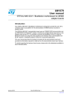
The block diagram of the demonstration kit is shown in Figure 1.
Figure 1. Demonstration board block diagram
&RQWURO6ZLWFKHV
UHVHWOHIWULJKW
0(06
GHYLFH
',/
&RQQHFWRU
$QDORJ
&RQWUROV
673')6
63,,&
$QDORJ
$'&
86%
670)5(7 &
86%
&RQQHFWRU
:LWK')8
)HDWXUH
3RZHU2Q/('
,QWHUUXSW/('V
*HQHUDO3XUSRVH/('V
$0Y
As shown in the Figure 1, the eMotion demonstration kit is based on the STM32F103RET6
microcontroller and can be connected to the PC through the USB bus. Data coming from the
MEMS sensor connected to the board can be read through the PC GUI provided with the kit.
The eMotion also implements the DFU (device firmware upgrade) feature, therefore, in the
case of a new firmware release, it can be reprogrammed without the need to use a
programmer. See www.st.com/mems for new firmware releases.
The eMotion also integrates three general-purpose LEDs, two LEDs connected directly to
the interrupt pins of digital adapters and the power/USB LED. Moreover, the eMotion
integrates three buttons: two are available to the user on a dedicated GPIO of the
microcontroller, while the other is used as reset for the microcontroller.
All the MEMS adapter pins are available on two connectors placed on the board (Figure 2
JP2 and JP3).
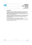
The top silkscreen view and image of the full board are shown in Figure 2 and Figure 3
respectively.
DocID017768 Rev 4
5/39
39
Demonstration kit description
UM0979
Figure 2. Top silkscreen of the eMotion kit
$0Y
6/39
DocID017768 Rev 4
UM0979
Demonstration kit description
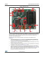
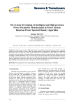
Figure 3. Board top view
ref 3
ref 2
ref 5
ref 4
ref 1
ref 13
ref 12
ref 6
ref 11
ref 10
ref 9
ref 8
ref 7
AM07758v1
In order to use the eMotion demonstration kit, installation of a dedicated driver is required,
which is included in the installation pack, together with a GUI interface which allows simple
interaction with the sensor. The steps required for driver and software installation are
described in the following sections.
In Figure 3 some main components placed on the top layer of the eMotion kit are
highlighted.
Jumpers JP9 and JP10 (Figure 3, ref 10, ref 11) are used to select the STM32 boot
mode. When the eMotion is used together with MEMS adapters, JP9 and JP10 must
be fitted (see STM32 datasheet for more information).
Jumper J2 (Figure 3, ref 7) can be used to directly supply the board (from 3.5 V to 6 V)
instead of using the USB connector.
Jumper JP1 allows the user to measure the sensor current consumption by connecting
a multimeter in series with its terminals (Figure 3, ref 9).
Jumpers JP4, JP5, and JP6 (Figure 3, ref 8) are used to manually set some features
which are available for just some of the analog MEMS adapters (see Table 1 for more
details). JP4 is used to set the self-test feature, JP5 to handle the power-down pin, and
JP6 to reset the MEMS high-pass filter. When they are fitted on pins 2-3, these
functions are handled by the firmware itself.
DocID017768 Rev 4
7/39
39
Demonstration kit description
UM0979
Table 1. Jumper configuration for power-down (PD), self test (ST) and high-pass filter
reset (HP)
8/39
Jumper on 1-2 position
Jumper on 2-3 position
Jumper unfitted
JP4
ST
logic level 1:
self-test ON
Self-test is handled by the
firmware
logic level 0:
self-test OFF, default
JP5
PD
logic level 1:
power-down mode
Power-down is handled by the
firmware
logic level 0:
normal mode, default
JP6
HP
logic level 1: external
high-pass filter reset
High-pass filter reset is
handled by the firmware
logic level 0:
normal mode, default
J1 connector (Figure 3, ref 3) can be used to both reprogram the STM32 and to debug
the code through the JTAG or SWD protocols.
Jumper JP7 (Figure 3, ref 4) is used to select either JTAG (JP7 unfitted) or SWD (JP7
fitted) mode.
eMotion also integrates six LEDs and three buttons:
–
LED D1 (Figure 3, ref 6) is switched on when the board is power supplied.
–
LEDs D2 and D3 (Figure 3, ref 13) are directly connected to the interrupt pins of
the MEMS digital adapters (if available on the sensor mounted on the adapter
board).
–
LEDs D4, D5, and D6 (Figure 3, ref 12) are general-purpose LEDs and are used
to indicate firmware states. For example, LED D6 is switched on when a specific
firmware is selected from those available. LED D5 on indicates that the
microcontroller is well configured for communication with the sensor. Finally the
LED D4 blinks according to the sensor data rate selected.
–
Button SW3 (Figure 3, ref 1) is used to reset the STM32.
–
Button SW1 and SW2 (Figure 3, ref 2 and ref 5) are connected to STM32 GPIOs
and are available to the user.
DocID017768 Rev 4
UM0979
2
eMotion board installation
eMotion board installation
The software package can be downloaded from the st.com website and includes the
following directory structure:
DRIVER: it contains the installation package for the USB drivers needed to connect the
eMotion board to the PC. No driver is needed on Linux and Mac OS platforms, so this
directory is included in the Windows installation package only.
DFU: it contains the .dfu files and the installation package for the software needed to
upgrade the firmware of the eMotion board.
FIRMWARE: it contains the source code of the firmware of the eMotion board together
with the corresponding binary file that can be flashed to the board using the DFU
software.
The section below describes the procedure to install the driver for the eMotion board
(needed on Windows platforms only) and the DFU software.
2.1
Hardware installation (Windows platforms)
No driver installation is needed on Linux and Mac OS platforms.
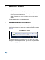
To install the STM32 virtual COM port driver on Windows platforms, launch the
“VCPDriver_V1.1_Setup.exe” included in the Windows installation package under the
“DRIVER” folder and follow the instructions on the screen. Once the driver is installed, insert
the demonstration kit board into a free USB port. A notification message should appear, as
in Figure 4.
Figure 4. Notification message
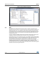
Now the eMotion should be recognized by the PC as a virtual COM. In order to confirm
which COM port has been assigned to the board, right click on “My Computer” and select
“Manage”, select “Device Manager” and scroll through the list until “Ports (COM & LPT)”. In
the following example (Figure 5) the COM11 has been assigned to the board.
DocID017768 Rev 4
9/39
39
eMotion board installation
UM0979
Figure 5. Virtual COM port assignment
2.2
DFU
The MEMS STEVAL-MKI109V2 demonstration board is capable of reprogramming an
application through the USB, in accordance with the DFU class specification defined by the
USB Implementers Forum. This capability is useful because it allows reprogramming the
microcontroller directly in the field and is particularly well-suited to USB applications where
the same USB connector can be used both for the standard operating mode and for the
reprogramming process.
In order to configure the eMotion board in DFU mode button SW2 must be pressed before
supplying the board and released when the LEDs D1, D4, D5, and D6 light up.
If the firmware version in use is lower than V3.0.0.0, it’s mandatory to patch the DFU feature
using the “DFU_Patcher_V1.0.2.dfu” file available under the “DFU” folder before proceeding
with the upgrade of the firmware with a version equal to or higher than V3.0.0.0. The
procedure to patch the DFU feature corresponds to the one used during a standard
firmware upgrade with the DFU tool. At the end of this procedure, if the green LED D4 is on,
it indicates that the procedure is successfully completed; if the red LED D5 is on, the
procedure failed and has to be repeated. Before proceeding with the new firmware upgrade
the board must be reset using the SW3 button.
10/39
DocID017768 Rev 4
UM0979
2.2.1
eMotion board installation
DFU on Windows
To install the DFU software, launch the “DfuSe_Demo_V3.0_Setup.exe” included in the
software package under the “DFU” folder and follow the instructions on the screen. To
launch the software, select “Start > STMicroelectronics > DfuSe > DfuSe Demonstration”.
In the ‘Upgrade or Verify Action’ section of the Dfuse Demo tool click on the ‘Choose...’
button and select the target .dfu file; then click the ‘Upgrade’ button to start the firmware
upgrade.
For more details regarding DFU and the microcontroller ST GUI, see the related user
manual located under “Start > STMicroelectronics > DfuSe > Docs > DfuSe Getting Started”.
2.2.2
DFU on Linux
The DFU program used for Linux operating systems is ‘dfu-util’.
The procedure for Ubuntu Linux operating systems is described below.
To install this program, open a terminal and write the following command (with sudo to
ensure having the correct permissions):
sudo apt-get install dfu-util
Create a udev rules file:
sudo gedit /etc/udev/49-emotion.rules
and fill it with the following content:
# 0483:5740 - STM32F4 in USB Serial Mode (CN5) ATTRS{idVendor}=="0483",
ATTRS{idProduct}=="5740", ENV{ID_MM_DEVICE_IGNORE}="1"
ATTRS{idVendor}=="0483", ATTRS{idProduct}=="5740", ENV{MTP_NO_PROBE}="1"
SUBSYSTEMS=="usb", ATTRS{idVendor}=="0483", ATTRS{idProduct}=="5740",
MODE:="0666"
KERNEL=="ttyACM*", ATTRS{idVendor}=="0483", ATTRS{idProduct}=="5740",
MODE:="0666"
# 0483:df11 - STM32F4 in DFU mode (CN5) SUBSYSTEMS=="usb",
ATTRS{idVendor}=="0483", ATTRS{idProduct}=="df11", MODE:="0666"
Tell udev to reload its rules:
sudo udevadm control --reload-rules
You should now be able to program the board. So, connect the eMotion board in DFU mode,
and run the following command:
sudo dfu-util -a 0 -D dfu_path/file.dfu -d 0483:df11
where dfu_path and file.dfu are the path to the dfu file and the dfu file name respectively
(example: sudo dfu-util -a 0 -D Desktop/eMotionV2_REL_4_0.dfu -d 0483:df11).
DocID017768 Rev 4
11/39
39
eMotion board installation
UM0979
To use the board with the upgraded firmware you need to disconnect and reconnect it, in
order to exit DFU mode.
2.2.3
DFU on Mac OS
The DFU program used for Mac operating systems is ‘dfu-util’. Before installing it, you need
to install Homebrew. To do that, you need to open a terminal and run the following
command:
ruby -e "$(curl -fsSL https://raw.github.com/Homebrew/homebrew/go/install)"
Once Homebrew is installed on your Mac, you can install dfu-utils with the following
command:
brew install dfu-util
You should now be able to program the board. So, connect the eMotion board in DFU mode,
and run the following command:
dfu-util -a 0 -D dfu_path/file.dfu -d 0483:df11
where dfu_path and file.dfu are the path to the dfu file and the dfu file name respectively
(example: dfu-util -a 0 -D Desktop/eMotionV2_REL_4_0.dfu -d 0483:df11).
To use the board with the upgraded firmware you need to disconnect and reconnect it, in
order to exit DFU mode.
12/39
DocID017768 Rev 4
UM0979
3
Supported MEMS adapter boards
Supported MEMS adapter boards
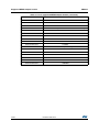
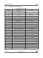
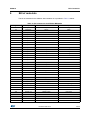
Table 2 below provides the complete list of supported adapter boards.
Table 2. List of supported MEMS adapter boards
Adapter board
Device
STEVAL-MKI009V1
LIS3LV02DL
STEVAL-MKI013V1
LIS302DL
STEVAL-MKI015V1
LIS344ALH
STEVAL-MKI074V1
LY330ALH
STEVAL-MKI075V1
LY3100ALH
STEVAL-MKI076V1
LY3200ALH
STEVAL-MKI082V1
LPY4150AL
STEVAL-MKI083V1
LPY450AL
STEVAL-MKI084V1
LPY430AL
STEVAL-MKI085V1
LPY410AL
STEVAL-MKI086V1
LPY403AL
STEVAL-MKI087V1
LIS331DL
STEVAL-MKI088V1
LIS33DE
STEVAL-MKI089V1
LIS331DLH
STEVAL-MKI090V1
LIS331DLF
STEVAL-MKI091V1
LIS331DLM
STEVAL-MKI092V1
LIS331HH
STEVAL-MKI095V1
LPR4150AL
STEVAL-MKI096V1
LPR450AL
STEVAL-MKI097V1
LPR430AL
STEVAL-MKI098V1
LPR410AL
STEVAL-MKI099V1
LPR403AL
STEVAL-MKI105V1
LIS3DH
STEVAL-MKI106V1
LSM303DLHC
STEVAL-MKI107V1
L3G4200D
STEVAL-MKI107V2
L3GD20
STEVAL-MKI108V1
9AXISMODULE v1 [LSM303DLHC + L3G4200D]
STEVAL-MKI108V2
9AXISMODULE v2 [LSM303DLHC + L3GD20]
STEVAL-MKI110V1
AIS328DQ
STEVAL-MKI113V1
LSM303DLM
STEVAL-MKI114V1
MAG PROBE (based on LSM303DLHC)
DocID017768 Rev 4
13/39
39
Supported MEMS adapter boards
UM0979
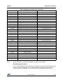
Table 2. List of supported MEMS adapter boards (continued)
14/39
Adapter board
Device
STEVAL-MKI120V1
LPS331AP
STEVAL-MKI122V1
LSM330DLC
STEVAL-MKI123V1
LSM330D
STEVAL-MKI124V1
10AXISMODULE [LSM303DLHC + L3GD20+ LPS331AP]
STEVAL-MKI125V1
A3G4250D
STEVAL-MKI133V1
LSM303D
STEVAL-MKI134V1
LIS3DSH
STEVAL-MKI135V1
LIS2DH
STEVAL-MKI136V1
L3GD20H
STEVAL-MKI137V1
LIS3MDL
STEVAL-MKI141V1
HTS221 (I2C i/f only)
STEVAL-MKI141V2
HTS221
STEVAL-MKI142V1
LPS25H
STEVAL-MKI151V1
LIS2DH12
STEVAL-MKI152V1
LIS2DM
STEVAL-MKI153V1
H3LIS331DL
STEVAL-MKI154V1
LSM9DS0
DocID017768 Rev 4
UM0979
4
Supported commands
Supported commands
The microcontroller mounted on the eMotion board is equipped with dedicated firmware that
supports a set of commands which allow to control either the digital or the analog output
MEMS sensor and permits the acquisition of the measured data. The firmware also handles
the communication between the board and the PC through the USB bus. These features
allow the user to easily write their own applications to exploit the capabilities of the sensor
chosen.
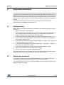
This section describes the commands that are supported by the firmware for the
microcontroller of the eMotion demonstration kit.
4.1
Getting started
Before using the commands supported by the firmware, the following procedure must be
performed:
1. Connect the eMotion to the USB port
2. Launch an application which allows to send commands through the virtual serial port.
The remainder of this document assumes the use of “Microsoft© HyperTerminal”
program available with the Windows XP operating system
3. Create a new connection, enter a name (e.g. “STEVAL-MKI109V2”), and click “OK”
4. In the “Connect Using” field, select the virtual COM port to which the USB port has
been mapped, and click “OK”
5. In port settings, set bits per second to 115200, data bits to 8, parity to none, stop bits to
1, and flow control to none. Click “OK”
6. In the “HyperTerminal” application window choose “files” > “properties” > “settings”,
then click on the “ASCII Setup” button
7. Select “Send line ends with line feeds” and “Echo typed characters locally”
8. Click the “OK” button to close the “ASCII Setup” window
9. Click the “OK” button to close the “Properties” window.
Once this procedure has been completed the user can utilize the commands described in
the following sections by typing them into the “HyperTerminal” window.
4.2
Supported commands
The firmware supports a wide range of MEMS adapters; the next section provides the
complete list of supported commands (see Table 3) and their description.
Then, split into sections, the list of commands available for each sensor supported by the
eMotion firmware is provided.
DocID017768 Rev 4
15/39
39
Supported commands
4.2.1
UM0979
Commands list and description
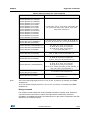
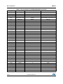
Table 3. Supported commands list
16/39
Command
Description
*setdbXXXVY
Selects firmware according to the adapter
connected
*start
Starts continuous data acquisition
(see Table 4)
*debug
Returns the output data in readable text
format
(see Table 5)
*stop
Stops data acquisition
*Zon
Forces 3-state
*Zoff
Exits from 3-state
*dev
Device name
e.g.: LIS3DH
*ver
Firmware version
e.g.: V1.0
*rAA
Accelerometer register read
e.g.: RAAhDDh
*wAADD
Accelerometer register write
*grAA
Gyroscope register read
*gwAADD
Gyroscope register write
*mrAA
Magnetometer register read
*mwAADD
Magnetometer register write
*prAA
Pressure sensor register read
*pwAADD
Pressure sensor register write
*hrAA
Humidity sensor register read
*hwAADD
Humidity sensor register write
*single
It gets a single X, Y, and Z data acquisition
(see Table 5)
*list
Prints the list of MKIs supported
e.g.: MKI105V1
*listdev
Prints the list of devices supported
e.g.: LIS3DH
*echoon
Activates the write verbose mode
e.g.: RAAhDDh
*echooff
Deactivates the write verbose mode
*fiforst
Accelerometer “Reset mode” enable
st 0 0 0 0 0 0 IR FC FS
*fifomde
Accelerometer “FIFO mode” enable
st 0 0 0 0 0 0 IR FC FS
*fifostr
Accelerometer “FIFO stream” enable
st 0 0 0 0 0 0 IR FC FS
*fifostf
Accelerometer “Stream to FIFO” enable
st 0 0 0 0 0 0 IR FC FS
*fifobtf
Accelerometer “Bypass to FIFO” enable
st 0 0 0 0 0 0 IR FC FS
*fifobts
Accelerometer “Bypass to stream” enable
st 0 0 0 0 0 0 IR FC FS
*fifodstr
Accelerometer “Dynamic stream” enable
st 0 0 0 0 0 0 IR FC FS
*gfiforst
Gyroscope “Reset mode” enable
st 0 0 0 0 0 0 IR FC FS
DocID017768 Rev 4
Returned value
e.g.: GRAAhDDh
e.g.: MRAAhDDh
e.g.: PRAAhDDh
e.g.: HRAAhDDh
UM0979
Supported commands
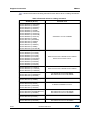
Table 3. Supported commands list (continued)
Note:
Command
Description
Returned value
*gfifomde
Gyroscope “FIFO mode” enable
st 0 0 0 0 0 0 IR FC FS
*gfifostr
Gyroscope “FIFO stream” enable
st 0 0 0 0 0 0 IR FC FS
*gfifostf
Gyroscope “Stream to FIFO” enable
st 0 0 0 0 0 0 IR FC FS
*gfifobtf
Gyroscope “Bypass to FIFO” enable
st 0 0 0 0 0 0 IR FC FS
*gfifobts
Gyroscope “Bypass to stream” enable
st 0 0 0 0 0 0 IR FC FS
*gfifodstr
Gyroscope “Dynamic stream” enable
st 0 0 0 0 0 0 IR FC FS
*mfiforst
Magnetometer “Reset mode” enable
st 0 0 0 0 0 0 IR FC FS
*mfifomde
Magnetometer “FIFO mode” enable
st 0 0 0 0 0 0 IR FC FS
*mfifostr
Magnetometer “FIFO stream” enable
st 0 0 0 0 0 0 IR FC FS
*mfifostf
Magnetometer “Stream to FIFO” enable
st 0 0 0 0 0 0 IR FC FS
*mfifobtf
Magnetometer “Bypass to FIFO” enable
st 0 0 0 0 0 0 IR FC FS
*mfifobts
Magnetometer “Bypass to stream” enable
st 0 0 0 0 0 0 IR FC FS
*mfifodstr
Magnetometer “Dynamic stream” enable
st 0 0 0 0 0 0 IR FC FS
*pfiforst
Pressure sensor “Reset mode” enable
st 0 0 0 0 0 0 IR FC FS
*pfifomde
Pressure sensor “FIFO mode” enable
st 0 0 0 0 0 0 IR FC FS
*pfifostr
Pressure sensor “FIFO stream” enable
st 0 0 0 0 0 0 IR FC FS
*pfifostf
Pressure sensor “Stream to FIFO” enable
st 0 0 0 0 0 0 IR FC FS
*pfifobtf
Pressure sensor “Bypass to FIFO” enable
st 0 0 0 0 0 0 IR FC FS
*pfifobts
Pressure sensor “Bypass to stream” enable
st 0 0 0 0 0 0 IR FC FS
*pfifodstr
Pressure sensor “Dynamic stream” enable
st 0 0 0 0 0 0 IR FC FS
*PDON
Set power-down pin
*PDOFF
Clears power-down pin
*STON
Sets self test pin
*STOFF
Clears self test pin
*HPON
Sets high-pass filter pin
*HPOFF
Clears high-pass filter pin
*FSON
Sets full scale pin
*FSOFF
Clears full scale pin
IR: interrupt byte; FC: FIFO control register; FS: FIFO source register.
Set demonstration board
The command *setdbxxxvy selects the part of the firmware able to handle the adapter board
sensor connected to the board. e.g., in order to select the firmware for the LIS3DH the
command must be: *setdb105V1. The D6 LED (green) is automatically switched on.
DocID017768 Rev 4
17/39
39
Supported commands
UM0979
Start command
The *start command initiates the continuous data acquisition. When this command is sent to
the device, it returns a string of bytes (plus carriage return and line feed) similar to “st OUT1
OUT2 OUT3 IR BT”.
The first two bytes are always the ASCII char “s” and “t” which correspond to the
hexadecimal values {73h 74h}.
OUT1, OUT2, and OUT3 are the bytes that contain the values measured at device outputs;
if the output data is represented on more than 8 bits, OUT1, OUT2, and OUT3 are split into
two bytes: high byte (e.g.: “XH”) and low byte (e.g.: “XL”).
IR contains the interrupt bytes and BT contains the bytes that describe the state of the
buttons integrated on the board.
Specifically, bit#0 of the “BT” data corresponds to the status of the SW1 button on the
demonstration kit board: it is set to 1 when the SW1 is pressed (otherwise 0). Bit#1 has the
same behavior but is dedicated to the SW2.
Before sending the *start command, the device must be out from 3-state and some registers
must be configured according to user needs, therefore, *start must be preceded by a *zoff
and some “Register Write” commands.
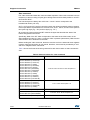
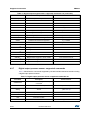
Table 4 shows the format of the string returned for each device when a *start command is
sent.
Table 4. Returned values for *start command
STEVAL # (Device)
Returned value
STEVAL-MKI009V1 (LIS3LV02DL)
STEVAL-MKI089V1 (LIS331DLH)
STEVAL-MKI092V1 (LIS331HH)
STEVAL-MKI105V1 (LIS3DH)
STEVAL-MKI107V1 (L3G4200D)
STEVAL-MKI107V2 (L3GD20)
STEVAL-MKI110V1 (AIS328DQ)
STEVAL-MKI125V1 (A3G4250D)
STEVAL-MKI134V1 (LIS3DSH)
STEVAL-MKI135V1 (LIS2DH)
STEVAL-MKI136V1 (L3GD20H)
STEVAL-MKI151V1 (LIS2DH12)
STEVAL-MKI153V1 (H3LIS331DL)
s t XH XL YH YL ZH ZL int1 int2 sw1|sw2 \r \n
STEVAL-MKI013V1 (LIS302DL)
STEVAL-MKI087V1 (LIS331DL)
STEVAL-MKI090V1 (LIS331DLF)
STEVAL-MKI091V1 (LIS331DLM)
STEVAL-MKI152V1 (LIS2DM)
s t X Y Z int1 int2 sw1|sw2 \r \n
STEVAL-MKI088V1 (LIS33DE)
s t X Y Z int1 sw1|sw2 \r \n
STEVAL-MKI015V1 (LIS344ALH)
STEVAL-MKI114V1 (MAG PROBE)
STEVAL-MKI137V1 (LIS3MDL)
18/39
s t XH XL YH YL ZH ZL sw1|sw2 \r \n
s t XH XL YH YL ZH ZL int1 sw1|sw2 \r \n
DocID017768 Rev 4
UM0979
Supported commands
Table 4. Returned values for *start command
STEVAL # (Device)
Returned value
STEVAL-MKI074V1 (LY330ALH)
STEVAL-MKI075V1 (LY3100ALH)
STEVAL-MKI076V1 (LY3200ALH)
STEVAL-MKI082V1 (LPY4150AL)
STEVAL-MKI083V1 (LPY450AL)
STEVAL-MKI084V1 (LPY430AL)
STEVAL-MKI085V1 (LPY410AL)
STEVAL-MKI086V1 (LPY403AL)
STEVAL-MKI095V1 (LPR4150AL)
STEVAL-MKI096V1 (LPR450AL)
STEVAL-MKI097V1 (LPR430AL)
STEVAL-MKI098V1 (LPR410AL)
STEVAL-MKI099V1 (LPR403AL)
s t vrefH vrefL o1H o1L out1H out1L out4H out4L o2H
o2L out2H out2L out5H out5L o3H o3L out3H out3L
out6H out6L sw1|sw2 \r \n
STEVAL-MKI106V1 (LSM303DLHC)
STEVAL-MKI113V1 (LSM303DLM)
STEVAL-MKI133V1 (LMS303D)
s t A_XH A_XL A_YH A_YL A_ZH A_ZL M_XH M_XL
M_YH M_YL M_ZH M_ZL A_int1 A_int2 sw1|sw2 \r \n
STEVAL-MKI108V1 (9AXISMODULEv1)
STEVAL-MKI108V2 (9AXISMODULEv2)
STEVAL-MKI154V1 (LSM9DS0)
STEVAL-MKI120V1 (LPS331AP)
STEVAL-MKI122V1 (LSM330DLC)
STEVAL-MKI123V1 (LSM330D)
s t PXL PL PH TL TH REF_PXL REF_PL REF_PH
REF_TL REF_TH int1 int 2 sw1|sw2 \r \n
s t A_XH A_XL A_YH A_YL A_ZH A_ZL
G_XH G_XL G_YH G_YL G_ZH G_ZL
A_int1 A_int2 G_int1 G_int2 sw1|sw2 \r \n
STEVAL-MKI124V1 (10AXISMODULE)
s t A_XH A_XL A_YH A_YL A_ZH A_ZL
G_XH G_XL G_YH G_YL G_ZH G_ZL
M_XH M_XL M_YH M_YL M_ZH M_ZL
PXL PL PH TL TH REF_PXL REF_PL REF_PH REF_TL
REF_TH A_int1 A_int2 sw1|sw2 \r \n
STEVAL-MKI141V1 (HTS221 - I2C i/f)
STEVAL-MKI141V2 (HTS221)
s t HL HH TL TH int1 sw1|sw2 \r \n
STEVAL-MKI142V1 (LPS25H)
Note:
s t A_XH A_XL A_YH A_YL A_ZH A_ZL
G_XH G_XL G_YH G_YL G_ZH G_ZL
M_XH M_XL M_YH M_YL M_ZH M_ZL
A_int1 A_int2 sw1|sw2 \r \n
s t PXL PL PH TL TH REF_PXL REF_PL REF_PH
int1 sw1|sw2 \r \n
XH: X-axis output high byte (same for Y axis, Z axis, P pressure, H humidity, and TEMP
temperature)
XL: X-axis output low byte (same for Y axis, Z axis, P pressure, H humidity, and TEMP
temperature)
Debug command
The *debug command starts the continuous data acquisition in debug mode. When this
command is sent to the board, it returns the output values measured by the device
formatted in a readable text format. The values shown on the screen correspond to the LSB
data shown as a decimal number.
DocID017768 Rev 4
19/39
39
Supported commands
UM0979
Table 5 shows the format of the string returned for each device when a *debug command is
sent.
Table 5. Returned values for *debug command
STEVAL # (Device)
Returned value
STEVAL-MKI009V1 (LIS3LV02DL)
STEVAL-MKI013V1 (LIS302DL)
STEVAL-MKI015V1 (LIS344ALH)
STEVAL-MKI087V1 (LIS331DL)
STEVAL-MKI088V1 (LIS33DE)
STEVAL-MKI089V1 (LIS331DLH)
STEVAL-MKI090V1 (LIS331DLF)
STEVAL-MKI091V1 (LIS331DLM)
STEVAL-MKI092V1 (LIS331HH)
STEVAL-MKI105V1 (LIS3DH)
STEVAL-MKI110V1 (AIS328DQ)
STEVAL-MKI134V1 (LIS3DSH)
STEVAL-MKI135V1 (LIS2DH)
STEVAL-MKI151V1 (LIS2DH12)
STEVAL-MKI152V1 (LIS2DM)
STEVAL-MKI153V1 (H3LIS331DL)
X=XXXXX Y=YYYYY Z=ZZZZZ
STEVAL-MKI082V1 (LPY4150AL)
STEVAL-MKI083V1 (LPY450AL)
STEVAL-MKI084V1 (LPY430AL)
STEVAL-MKI085V1 (LPY410AL)
STEVAL-MKI086V1 (LPY403AL)
STEVAL-MKI095V1 (LPR4150AL)
STEVAL-MKI096V1 (LPR450AL)
STEVAL-MKI097V1 (LPR430AL)
STEVAL-MKI098V1 (LPR410AL)
STEVAL-MKI099V1 (LPR403AL)
VREF=VVVVV OUT1=XXXXX 4OUT1=XXXXX
OUT3=YYYYY OUT6=YYYYY
STEVAL-MKI074V1 (LY330ALH)
STEVAL-MKI075V1 (LY3100ALH)
STEVAL-MKI076V1 (LY3200ALH)
VREF=VVVVV OUT1=XXXXX 4OUT1=XXXXX
STEVAL-MKI106V1 (LSM303DLHC)
STEVAL-MKI113V1 (LSM303DLM)
STEVAL-MKI133V1 (LSM303D)
AX=XXXXX AY=YYYYY AZ=ZZZZZ
MX=XXXXX MY=YYYYY MZ=ZZZZZ
STEVAL-MKI114V1 (MAG PROBE)
STEVAL-MKI137V1 (LIS3MDL)
MX=XXXXX MY=YYYYY MZ=ZZZZZ
STEVAL-MKI107V1 (L3G4200D)
STEVAL-MKI107V2 (L3GD20)
STEVAL-MKI125V1 (A3G4250D)
STEVAL-MKI136V1 (L3GD20H)
STEVAL-MKI108V1 (9AXISMODULEV1)
STEVAL-MKI108V2 (9AXISMODULEV2)
STEVAL-MKI154V1 (LSM9DS0)
P=PPPPP R=RRRRR Y=YYYYY
AX=XXXXX AY=YYYYY AZ=ZZZZZ
MX=XXXXX MY=YYYYY MZ=ZZZZZ
GX=XXXXX GY=YYYYY GZ=ZZZZZ
STEVAL-MKI120V1 (LPS331AP)
STEVAL-MKI142V1 (LPS25H)
STEVAL-MKI122V1 (LSM330DLC)
STEVAL-MKI123V1 (LSM330D)
20/39
DocID017768 Rev 4
P=PPPPP T=TTTTT
AX=XXXXX AY=YYYYY AZ=ZZZZZ
GX=XXXXX GY=YYYYY GZ=ZZZZZ
UM0979
Supported commands
Table 5. Returned values for *debug command
STEVAL # (Device)
Returned value
STEVAL-MKI124V1 (10AXISMODULE)
AX=XXXXX AY=YYYYY AZ=ZZZZZ
MX=XXXXX MY=YYYYY MZ=ZZZZZ
GX=XXXXX GY=YYYYY GZ=ZZZZZ
P=PPPPP T=TTTTT
STEVAL-MKI141V1 (HTS221 - I2C i/f)
STEVAL-MKI141V2 (HTS221)
H=HHHHH T=TTTTT
Stop command
The *stop command interrupts any acquisition session that has been started with either the
*start or *debug commands.
Zon and Zoff
The *Zon and *Zoff commands are employed, respectively, to put into 3-state the
STM32F103RET6 microcontroller mounted on the demonstration kit. These commands
allow the isolation of the sensor from the microprocessor and let the user interact with the
sensor in a pure analog way.
By default, when the kit is first turned on, the lines are in 3-state mode and the user is
required to send the *Zoff command to allow communication between the sensor and the
microcontroller. If Zoff has not been launched, the firmware ignores any other command.
Device name
The *dev command retrieves the name of the adapter connected to the demonstration kit.
The returned value is, for example, “LIS3DH”.
Firmware version
The *ver command queries the demonstration kit and returns the version of the firmware
loaded in the microprocessor, for example, “V1.0”.
Accelerometer register read
The *rAA command allows the contents of the accelerometer registers in the demonstration
kit board to be read. AA, expressed as a hexadecimal value and written in upper case,
represents the address of the register to be read.
Once the read command is issued, the board returns RAAhDDh, where AA is the address
sent by the user and DD is the data present in the register.
For example, to read the register at address 0x20, the user issues the command *r20, which
returns, e.g., R20hC7h.
Accelerometer register write
The *wAADD command allows writing to the contents of the accelerometer registers in the
demonstration kit board. AA and DD, expressed as hexadecimal values and written in upper
case, represent, respectively, the address of the register and the data to be written. For
example, to write 0xC7 to the register at address 0x20, the user issues the command
*w20C7.
DocID017768 Rev 4
21/39
39
Supported commands
UM0979
Gyroscope register read
The *grAA command allows the contents of the gyroscope registers in the demonstration kit
board to be read. AA, expressed as hexadecimal value and written in upper case,
represents the address of the register to be read.
Once the read command is issued, the board returns GRAAhDDh, where AA is the address
sent by the user and DD is the data present in the register.
For example, to read the register at address 0x20, the user issues the command *gr20,
which returns, e.g., GR20hC7h.
Gyroscope register write
The *gwAADD command allows writing to the contents of the gyroscope registers in the
demonstration kit board. AA and DD, expressed as hexadecimal values and written in upper
case, represent, respectively, the address of the register and the data to be written. To write
0xC7 to the register at address 0x20, for example, the user issues the command *gw20C7.
Magnetometer register read
The *mrAA command allows the contents of the magnetometer registers in the
demonstration kit board to be read. AA, expressed as a hexadecimal value and written in
upper case, represents the address of the register to be read.
Once the read command is issued, the board returns MRAAhDDh, where AA is the address
sent by the user and DD is the data present in the register.
For example, to read the register at address 0x00, the user issues the command *mr00,
which returns, e.g., MR00h10h.
Magnetometer register write
The *mwAADD command allows writing to the contents of the magnetometer registers in
the demonstration kit board. AA and DD, expressed as hexadecimal values and written in
upper case, represent, respectively, the address of the register and the data to be written. To
write 0x20 to the register at address 0x01, for example, the user issues the command
*mw0120.
Pressure sensor register read
The *prAA command allows the contents of the pressure sensor registers in the
demonstration kit board to be read. AA, expressed as a hexadecimal value and written in
upper case, represents the address of the register to be read.
Once the read command is issued, the board returns PRAAhDDh, where AA is the address
sent by the user and DD is the data present in the register.
For example, to read the register at address 0x20, the user issues the command *pr20,
which returns, e.g., PR20h10h.
Pressure sensor register write
The *pwAADD command allows writing to the contents of the pressure sensor registers in
the demonstration kit board. AA and DD, expressed as hexadecimal values and written in
upper case, represent, respectively, the address of the register and the data to be written. To
write 0xC7 to the register at address 0x20, for example, the user issues the command
*pw20C7.
22/39
DocID017768 Rev 4
UM0979
Supported commands
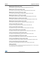
Humidity sensor register read
The *hrAA command allows the contents of the humidity sensor registers in the
demonstration kit board to be read. AA, expressed as a hexadecimal value and written in
upper case, represents the address of the register to be read.
Once the read command is issued, the board returns HRAAhDDh, where AA is the address
sent by the user and DD is the data present in the register.
For example, to read the register at address 0x20, the user issues the command *hr20,
which returns, e.g., HR20h10h.
Humidity sensor register write
The *hwAADD command allows writing to the contents of the humidity sensor registers in
the demonstration kit board. AA and DD, expressed as hexadecimal values and written in
upper case, represent, respectively, the address of the register and the data to be written. To
write 0xC7 to the register at address 0x20, for example, the user issues the command
*hw20C7.
Single acquisition
The *single command may be used to read just one set of data. It requires the sensor to be
well configured and once invoked, returns the read values of one data sample.
The format of the returned value is exactly the same as the *debug command (Table 5), in
fact, the *debug command is used for continuous data acquisition purposes whereas a
*single command returns just one set of data.
List
The *list command returns the list of MKI adapters supported by the firmware, printed in
ASCII format.
Listdev
The *listdev command returns the list of devices supported by the firmware, printed in ASCII
format.
Echo on
The *echoon command is used to activate the write command verbose mode. Once this
command is launched, after every write command the firmware automatically performs also
a read of the register just written. This function is useful to check if the write has succeeded.
For instance, if the *echoon command is launched, after a *w2027 it results R2027.
Echo off
The *echooff command stops the write command verbose mode.
Accelerometer FIFO reset enable
The *fiforst command enables the accelerometer FIFO reset mode. For more details see the
AN3308 application note.
DocID017768 Rev 4
23/39
39
Supported commands
UM0979
Accelerometer FIFO mode enable
The *fifomde command is used to enable the accelerometer FIFO mode. For more details
see the AN3308 application note.
Accelerometer FIFO stream mode enable
The *fifostr command is used to enable the accelerometer FIFO stream mode. For more
details see the AN3308 application note.
Accelerometer Stream-to-FIFO mode enable
The *fifostf command enables the accelerometer Stream-to-FIFO mode. For more details
see the AN3308 application note.
Accelerometer Bypass-to-FIFO mode enable
The *fifobtf command is used to enable the accelerometer Bypass-to-FIFO mode.
Accelerometer Bypass-to-Stream mode enable
The *fifobts command is used to enable the accelerometer Bypass-to-Stream mode.
Accelerometer Dynamic Stream mode enable
The *fifodstr command enables the accelerometer Dynamic Stream mode.
Gyroscope FIFO reset enable
The *gfiforst command enables the gyroscope FIFO reset mode.
Gyroscope FIFO mode enable
The *gfifomde command is used to enable the gyroscope FIFO mode.
Gyroscope FIFO stream mode enable
The *gfifostr command is used to enable the gyroscope FIFO stream mode.
Gyroscope Stream to FIFO mode enable
The *gfifostf command enables the gyroscope Stream-to-FIFO mode.
Gyroscope Bypass to FIFO mode enable
The *gfifobtf command is used to enable the gyroscope Bypass-to-FIFO mode.
Gyroscope Bypass to Stream mode enable
The *gfifobts command is used to enable the gyroscope Bypass-to-Stream mode.
Gyroscope Dynamic Stream mode enable
The *gfifodstr command enables the gyroscope Dynamic Stream mode.
Magnetometer FIFO reset enable
The *mfiforst command enables the magnetometer FIFO reset mode.
24/39
DocID017768 Rev 4
UM0979
Supported commands
Magnetometer FIFO mode enable
The *mfifomde command is used to enable the magnetometer FIFO mode.
Magnetometer FIFO stream mode enable
The *mfifostr command is used to enable the magnetometer FIFO stream mode.
Magnetometer Stream to FIFO mode enable
The *mfifostf command enables the magnetometer Stream-to-FIFO mode.
Magnetometer Bypass to FIFO mode enable
The *mfifobtf command is used to enable the magnetometer Bypass-to-FIFO mode.
Magnetometer Bypass to Stream mode enable
The *mfifobts command is used to enable the magnetometer Bypass-to-Stream mode.
Magnetometer Dynamic Stream mode enable
The *mfifodstr command enables the magnetometer Dynamic Stream mode.
Pressure sensor FIFO reset enable
The *pfiforst command enables the pressure sensor FIFO reset mode.
Pressure sensor FIFO mode enable
The *pfifomde command is used to enable the pressure sensor FIFO mode.
Pressure sensor FIFO stream mode enable
The *pfifostr command is used to enable the pressure sensor FIFO stream mode.
Pressure sensor Stream to FIFO mode enable
The *pfifostf command enables the pressure sensor Stream-to-FIFO mode.
Pressure sensor Bypass to FIFO mode enable
The *pfifobtf command is used to enable the pressure sensor Bypass-to-FIFO mode.
Pressure sensor Bypass to Stream mode enable
The *pfifobts command is used to enable the pressure sensor Bypass-to-Stream mode.
Pressure sensor Dynamic Stream mode enable
The *pfifodstr command enables the pressure sensor Dynamic Stream mode.
PDON and PDOFF
The *PDON and *PDOFF commands are employed respectively to set to 1, and to clear to
0, the “power-down” pin in analog devices.
DocID017768 Rev 4
25/39
39
Supported commands
UM0979
STON and STOFF
The *STON and *STOFF commands are employed respectively to set to 1, and to clear to 0,
the “self test” pin in analog devices.
HPON and HPOFF
The *HPON and *HPOFF commands are employed respectively to set to 1, and to clear to
0, the “high-pass filter” pin in analog devices.
FSON and FSOFF
The *FSON and *FSOFF commands are employed respectively to set to 1 and to clear to 0
the “full scale” pin in analog devices.
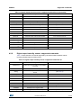
4.2.2
Digital output accelerometers: supported commands
Table 6 below lists the commands supported by the devices/demonstration boards including
a digital output accelerometer.
Table 6. Digital output accelerometers: supported commands list
Command
Description
*setdbXXXVY
Selects firmware according to the adapter
connected
*start
Starts continuous data acquisition
(see Table 4)
*debug
Returns the output data in readable text format
(see Table 5)
*stop
Stops data acquisition
*Zon
Forces 3-state
*Zoff
Exits from 3-state
*dev
Device name
e.g.: LIS3DH
*ver
Firmware version
e.g.: V1.0
*rAA
Accelerometer register read
e.g.: RAAhDDh
*wAADD
Accelerometer register write
*single
It gets a single X, Y, and Z data acquisition
(see Table 5)
*list
Prints the list of MKIs supported
e.g.: MKI105V1
*listdev
Prints the list of devices supported
e.g.: LIS3DH
*echoon
Activates the write verbose mode
e.g.: RAAhDDh
*echooff
Deactivates the write verbose mode
*fiforst(1)
Accelerometer “Reset mode” enable
st 0 0 0 0 0 0 IR FC FS
(1)
Accelerometer “FIFO mode” enable
st 0 0 0 0 0 0 IR FC FS
(1)
Accelerometer “FIFO stream” enable
st 0 0 0 0 0 0 IR FC FS
(1)
*fifostf
Accelerometer “Stream-to-FIFO” enable
st 0 0 0 0 0 0 IR FC FS
*fifobtf(1)
Accelerometer “Bypass-to-FIFO” enable
st 0 0 0 0 0 0 IR FC FS
*fifomde
*fifostr
26/39
Returned value
DocID017768 Rev 4
UM0979
Supported commands
Table 6. Digital output accelerometers: supported commands list (continued)
Command
(1)
*fifobts
*fifodstr(1)
Description
Returned value
Accelerometer “Bypass-to-Stream” enable
st 0 0 0 0 0 0 IR FC FS
Accelerometer “Dynamic Stream” enable
st 0 0 0 0 0 0 IR FC FS
1. Available only for devices with embedded FIFO.
Note:
IR: interrupt byte; FC: FIFO control register; FS: FIFO source register.
4.2.3
Analog output accelerometers: supported commands
Table 7 below lists the commands supported by the devices/demonstration boards including
an analog output accelerometer:
Table 7. Analog output accelerometers: supported commands list
Command
Description
*setdbXXXVY
Selects firmware according to the adapter
connected
*start
Starts continuous data acquisition
(see Table 4)
*debug
Returns the output data in readable text
format
(see Table 5)
*stop
Stops data acquisition
*Zon
Forces 3-state
*Zoff
Exits from 3-state
*dev
Device name
e.g.: LIS3DH
*ver
Firmware version
e.g.: V1.0
*single
It gets a single X, Y, and Z data acquisition
(see Table 5)
*list
Prints the list of MKIs supported
e.g.: MKI105V1
*listdev
Prints the list of devices supported
e.g.: LIS3DH
*echoon
Activates the write verbose mode
e.g.: RAAhDDh
*echooff
Deactivates the write verbose mode
*PDON
Sets power-down pin
*PDOFF
Clears power -down pin
*STON
Sets self test pin
*STOFF
Clears self test pin
*FSON
Sets full scale pin
*FSOFF
Clears full scale pin
DocID017768 Rev 4
Returned value
27/39
39
Supported commands
4.2.4
UM0979
Digital output gyroscopes: supported commands
Table 8 below lists the commands supported by the devices/demonstration boards including
a digital output gyroscope:
Table 8. Digital output gyroscopes: supported commands list
Command
Description
*setdbXXXVY
Selects firmware according to the adapter
connected
*start
Starts continuous data acquisition
(see Table 4)
*debug
Returns the output data in readable text
format
(see Table 5)
*stop
Stops data acquisition
*Zon
Forces 3-state
*Zoff
Exits from 3-state
*dev
Device name
e.g.: LIS3DH
*ver
Firmware version
e.g.: V1.0
*grAA
Gyroscope register read
e.g.: GRAAhDDh
*gwAADD
Gyroscope register write
*single
It gets a single X, Y, and Z data acquisition
(see Table 5)
*list
Prints the list of MKIs supported
e.g.: MKI105V1
*listdev
Prints the list of devices supported
e.g.: LIS3DH
*echoon
Activates the write verbose mode
e.g.: RAAhDDh
*echooff
Deactivates the write verbose mode
*gfiforst
(1)
*gfifomde(1)
Returned value
Gyroscope “Reset mode” enable
st 0 0 0 0 0 0 IR FC FS
Gyroscope “FIFO mode” enable
st 0 0 0 0 0 0 IR FC FS
(1)
Gyroscope “FIFO stream” enable
st 0 0 0 0 0 0 IR FC FS
(1)
Gyroscope “Stream to FIFO” enable
st 0 0 0 0 0 0 IR FC FS
(1)
Gyroscope “Bypass to FIFO” enable
st 0 0 0 0 0 0 IR FC FS
Gyroscope “Bypass to stream” enable
st 0 0 0 0 0 0 IR FC FS
Gyroscope “Dynamic stream” enable
st 0 0 0 0 0 0 IR FC FS
*gfifostr
*gfifostf
*gfifobtf
*gfifobts(1)
(1)
*gfifodstr
1. Available only for devices with embedded FIFO.
Note:
28/39
IR: interrupt byte; FC: FIFO control register; FS: FIFO source register.
DocID017768 Rev 4
UM0979
4.2.5
Supported commands
Analog output gyroscopes: supported commands
Table 9 below lists the commands supported by the devices/demonstration boards including
an analog output gyroscope:
Table 9. Analog output gyroscopes: supported commands list
Command
Description
*setdbXXXVY
Selects firmware according to the adapter
connected
*start
Starts continuous data acquisition
(see Table 4)
*debug
Returns the output data in readable text
format
(see Table 5)
*stop
Stops data acquisition
*Zon
Forces 3-state
*Zoff
Exits from 3-state
*dev
Device name
e.g.: LIS3DH
*ver
Firmware version
e.g.: V1.0
*single
It gets a single X, Y, and Z data acquisition
(see Table 5)
*list
Prints the list of MKIs supported
e.g.: MKI105V1
*listdev
Prints the list of devices supported
e.g.: LIS3DH
*echoon
Activates the write verbose mode
e.g.: RAAhDDh
*echooff
Deactivates the write verbose mode
*PDON
Sets power-down pin
*PDOFF
Clears power-down pin
*STON
Sets self test pin
*STOFF
Clears self test pin
*HPON
Sets high-pass filter pin
*HPOFF
Clears high-pass filter pin
4.2.6
Returned value
Digital output magnetometers: supported commands
Table 10 below lists the commands supported by the devices/demonstration boards
including a digital output magnetometer:
Table 10. Digital output magnetometer: supported commands list
Command
Description
*setdbXXXVY
Selects firmware according to the adapter
connected
*start
Starts continuous data acquisition
(see Table 4)
*debug
Returns the output data in readable text
format
(see Table 5)
DocID017768 Rev 4
Returned value
29/39
39
Supported commands
UM0979
Table 10. Digital output magnetometer: supported commands list (continued)
Command
Description
*stop
Stops data acquisition
*Zon
Forces 3-state
*Zoff
Exits from 3-state
*dev
Device name
e.g.: LIS3DH
*ver
Firmware version
e.g.: V1.0
*mrAA
Magnetometer register read
e.g.: MRAAhDDh
*mwAADD
Magnetometer register write
*single
It gets a single X, Y, and Z data acquisition
(see Table 5)
*list
Prints the list of MKIs supported
e.g.: MKI105V1
*listdev
Prints the list of devices supported
e.g.: LIS3DH
*echoon
Activates the write verbose mode
e.g.: MRAAhDDh
*echooff
Deactivates the write verbose mode
*mfiforst
(1)
*mfifomde(1)
Magnetometer “Reset mode” enable
st 0 0 0 0 0 0 IR FC FS
Magnetometer “FIFO mode” enable
st 0 0 0 0 0 0 IR FC FS
(1)
Magnetometer “FIFO stream” enable
st 0 0 0 0 0 0 IR FC FS
(1)
Magnetometer “Stream to FIFO” enable
st 0 0 0 0 0 0 IR FC FS
(1)
Magnetometer “Bypass to FIFO” enable
st 0 0 0 0 0 0 IR FC FS
Magnetometer “Bypass to stream” enable
st 0 0 0 0 0 0 IR FC FS
Magnetometer “Dynamic stream” enable
st 0 0 0 0 0 0 IR FC FS
*mfifostr
*mfifostf
Returned value
*mfifobtf
*mfifobts(1)
*mfifodstr
(1)
1. Available only for devices with embedded FIFO.
4.2.7
Digital output pressure sensor: supported commands
Table 11 below lists the commands supported by the devices/demonstration boards including
a digital output pressure sensor:
Table 11. Digital output pressure sensor: supported commands list
30/39
Command
Description
*setdbXXXVY
Selects firmware according to the adapter
connected
*start
Starts continuous data acquisition
(see Table 4)
*debug
Returns the output data in readable text
format
(see Table 5)
*stop
Stops data acquisition
*Zon
Forces 3-state
*Zoff
Exits from 3-state
*dev
Device name
DocID017768 Rev 4
Returned value
e.g.: LIS3DH
UM0979
Supported commands
Table 11. Digital output pressure sensor: supported commands list (continued)
Command
Description
Returned value
*ver
Firmware version
e.g.: V1.0
*prAA
Pressure sensor register read
e.g.: PRAAhDDh
*pwAADD
Pressure sensor register write
*single
It gets a single X, Y, and Z data acquisition
(see Table 5)
*list
Prints the list of MKIs supported
e.g.: MKI105V1
*listdev
Prints the list of devices supported
e.g.: LIS3DH
*echoon
Activates the write verbose mode
e.g.: PRAAhDDh
*echooff
Deactivates the write verbose mode
*pfiforst
(1)
*pfifomde(1)
Pressure sensor “Reset mode” enable
st 0 0 0 0 0 0 IR FC FS
Pressure sensor “FIFO mode” enable
st 0 0 0 0 0 0 IR FC FS
(1)
Pressure sensor “FIFO stream” enable
st 0 0 0 0 0 0 IR FC FS
(1)
Pressure sensor “Stream to FIFO” enable
st 0 0 0 0 0 0 IR FC FS
(1)
Pressure sensor “Bypass to FIFO” enable
st 0 0 0 0 0 0 IR FC FS
Pressure sensor “Bypass to stream” enable
st 0 0 0 0 0 0 IR FC FS
Pressure sensor “Dynamic stream” enable
st 0 0 0 0 0 0 IR FC FS
*pfifostr
*pfifostf
*pfifobtf
*pfifobts(1)
(1)
*pfifodstr
1. Available only for devices with embedded FIFO.
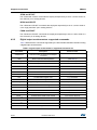
4.2.8
Digital output humidity sensor: supported commands
Table 11 below lists the commands supported by the devices/demonstration boards
including a digital output humidity sensor:
Table 12. Digital output humidity sensor: supported commands list
Command
Description
*setdbXXXVY
Selects firmware according to the adapter
connected
*start
Starts continuous data acquisition
(see Table 4)
*debug
Returns the output data in readable text
format
(see Table 5)
*stop
Stops data acquisition
*Zon
Forces 3-state
*Zoff
Exits from 3-state
*dev
Device name
e.g.: LIS3DH
*ver
Firmware version
e.g.: V1.0
*hrAA
Humidity sensor register read
e.g.: HRAAhDDh
*hwAADD
Humidity sensor register write
*single
It gets a single X, Y, and Z data acquisition
DocID017768 Rev 4
Returned value
(see Table 5)
31/39
39
Supported commands
UM0979
Table 12. Digital output humidity sensor: supported commands list (continued)
4.3
Command
Description
Returned value
*list
Prints the list of MKIs supported
e.g.: MKI105V1
*listdev
Prints the list of devices supported
e.g.: LIS3DH
*echoon
Activates the write verbose mode
e.g.: PRAAhDDh
*echooff
Deactivates the write verbose mode
Quick start
This section shows the basic sequence of commands, based on the LIS3DH accelerometer,
to start a data communication session and to retrieve the X, Y, and Z acceleration data from
the demonstration kit:
1. Connect the eMotion to the USB port
2. Start “Microsoft© HyperTerminal” and configure it as described in Section 4.1
3. Inside the “HyperTerminal” window, enter the command *setdb105v1 (supposing the
LIS3DH adapter board is used, for other adapters see the relevant datasheets to check
the register configuration), enter the command *Zoff to enable the control of the device
by the STM32F103RET6 microcontroller, and *w2047 to switch on the LIS3DH and to
set the data rate to 50 Hz
4. Send the *debug command to get the X, Y, and Z data measured by the sensor
5. Send *stop to end the continuous acquisition and visualization.
32/39
DocID017768 Rev 4
DocID017768 Rev 4
-
9
'0
'3
QF
*1'
0LQL86%%
*1'
*1'
&
X)
*1'
.
5
86%B9
5
5
*1'
5
.
5
.
86%B9
5
4
%&
& Q)
&
Q)
8
,2 ,2
*1' 9EXV
,2 ,2
86%/&3
5
86%B9
86%B'LVF
5
.
9''
5
.
86%'3
86%'0
5
5
'
&
&
Q) X)
1RWPRXQWHG
9SV
73
4
5
%& 5
9''
3RZHU6XSSO\
86%B9
*1'
Q)
&
9GGBGXW
86%B'LVF
86%'3
86%'0
OGV[[
9RXW
*QG
(1 %<3$66
9LQ
8
-3
9GGBGXW
86%B'LVF
86%'3
86%'0
9GGBGXW
&XUUHQWB0HDVXUH
7$17
&
&
Q)
X)
9''
5
-
UM0979
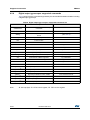
Schematic diagrams
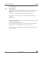
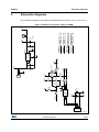
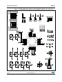
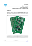
Schematic diagrams
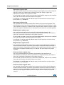
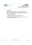
The schematics diagram of the eMotion demonstration kit is shown in Figure 6 and Figure 7.
Figure 6. eMotion board (power supply and USB)
$0Y
33/39
39
DocID017768 Rev 4
5
0
,Q
5
.
5
.
9UHI
2
5 5
. .
-706B6:',2
-7&.B6:&/.
-7'2
-7',
1567
&RVF
S)
26&287
8&
76
9'' 9''
2VF
0+]
9''
6:'&RQQHFWRU
-
,Q
9''
,Q
8$
76
287
-17567
5
.
-3
5
5
5
5
287BX
9''
287BX
287BX
5
-3
9''
287
287
287
6:
26&,1
26&287
1567
2BX
*3B*3,2 ,17
,17
287BX
287BX
9UHIBX
Q)
)6
9''
-3
%227
&
X)
&
Q)
&
5
5
5
5
5
5
%227
5
.
6:
287
8'
76
8%
76
8'
76
9''
5
.
,Q
,Q
9''
,Q
,Q
9''
,Q
,Q
9''
,Q
,Q
&
Q)
5
.
6:
6:
9''
9EDW
3&7DPSHU57&
3&26&LQ
3&26&RXW
3'26&LQ
3'26&RXW
1567
3&$'&
3&$'&
3&$'&
3&$'&
9VV$
9GG$
3$:.83$'&
3$$'&
3$$'&
9''
&
X)
5
.
9''
,&B6'$
,&B6&/
5
.
2BX
2BX
9''
5
.
6:
9''
&
Q)
*3BOHG
'
5
5
9''
*OHG
'
5
5
&
Q)
9''
2
2
8%
76
8$
76
'
9''
Q)
5OHG
5
5
&(B5)
&6B'(9
63,B 6'$
6'2B'(9
63,B 6&/
86%B'LVF
'
5
5
1RW0RXQWHG
+HDGHU
-3
'
5
5
9GGBGXW
86%B'LVF
86%'3
,17
,17
+HDGHU ;
-3
9GGBGXW
86%B'LVF
86%'3
86%'0
1RW0RXQWHG
86%'0
1RW0RXQWHG
-3
+HDGHU
-706B6:',2
86%'3
86%'0
86$575;
86$577;
+3BX
9''
&
670)[5[
,Q
,Q
9''
,Q
,Q
9''
9GG
9VV
3$-7066:',2
3$86%'3
3$86%'0
3$86$57B5;
3$86$57B7;
3$0&2
3&
3&
3&
3&
3%63,026,
3%63,B0,62
3%63,B6&.
3%63,B166
&6B5)
,54B5)
%227
287BX
287BX
287BX
2BX
026,B5)
0,62B5)
6&.B5)
2BX
287BX
1RW0RXQWHG
,Q
9''
,Q
8&
76
287
5
9GG
9VV
3%
3%
3%%227
3%$'&
3%$'&
3&$'&
3&$'&
3$026,$'&
3$0,62$'&
3$6&.$'&
3$166$'&
9GG
9VV
3$$'&
&RVF
S)
,Q
9''
,Q
287BX
8%
76
3$-7&.6:&/.
3$-7',
3&
3&
3&
3'
3%-7'2
3%-17567
3%
3%,&B6&/
3%,&B6'$
%227
3%
3%
9VV
9GG
9''
2BX
,Q
8$
76
%227
6:
6:
26&,1
9UHIBX
287BX 287BX
9''
-7&.B6:&/.
-7',
*OHG
5OHG
67BX
3'BX
-7'2
-17567
*3BOHG
34/39
9''
287
287
2
287
9UHI
287
287
2
287
2
9GGBG XW
-
&(B5)
&6B5)
6&.B5)
026,B5)
0,62B5)
,54B5)
9''
+3
-3
3'
-3
67
-3
5
5
5
63,B 6&/
63,B 6'$
5
.
+3
5
.
3'
5
.
67
6'$B'(9
6&/B'(9
0+'5;
-3
9''
+3BX
9''
3'BX
9''
67BX
5
5
5
5
5
,&B6'$
,&B6&/
*3B*3,2
+3
6'2B'(9
6'$B'(9
6&/B'(9
&6B'(9
3'
)6
67
,17
,17
',/'HYLFH$GDSWHU
+HDGHU +HDGHU
-
1RW0RXQWHG
+HDGHU ;
-3
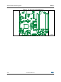
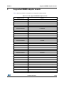
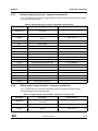
Schematic diagrams
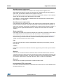
UM0979
Figure 7. STEVAL-MKI109V2 eMotion board (STM32F103RET6 and connectors)
$0Y
UM0979
6
Bill of materials
Bill of materials
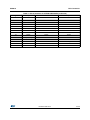
The bill of materials for the eMotion demonstration kit is provided in Table 13 below.
Table 13. Bill of materials for STEVAL-MKI109V2
Designator
Description
Comment
Footprint
C1
Capacitor
10 μF
C1206_POL
C2
Capacitor
100 nF
0805
C3
Capacitor
100 nF
0805
C4
Capacitor
100 nF
0805
C5
Capacitor
100 nF
0805
C6
Capacitor
100 nF
0805
C7
Capacitor
100 nF
0805
C8
Capacitor
100 nF
0805
C9
Capacitor
100 nF
0805
C10
Capacitor
4.7 μF
C0805_POL
C11
Capacitor
1 μF
0805
C12
Capacitor
1 μF
C0805_POL
C13
Capacitor
10 μF
C0805_POL
C14
Capacitor
33 nF
0805
C17
Capacitor
10 nF
0805
C26
Capacitor
100 nF
0805
Cosc1
Capacitor
18 pF
0805
Cosc2
Capacitor
18 pF
0805
D1
SMD LED
Blue LED
0805
D2
SMD LED
Green LED
0805
D3
SMD LED
Orange LED
0805
D4
SMD LED
Green LED
0805
D5
SMD LED
Red LED
0805
D6
SMD LED
Orange LED
0805
J1
Header_HE10_5X2
JTAG/SWD connector
HDR5X2 1.27 mm
J2
CON2
Power supply
Header 1x2 2 mm
J3
USB_mini_B
Mini-USB B
USB_mini_B
J4
Header 12
Header 12
HDR1X12
J5
Header 12
Header 12
JP 1X12
JP1
CON2
Current_Measure
Header 1x2 2 mm
JP2
Header 12
Header 12X2
HDR1X12
JP3
Header 12
Header 12X2
HDR1X12
JP4
Header 3
STMicroelectronics
Header 1x3 2 mm
JP5
Header 3
PD
Header 1x3 2 mm
JP6
Header 3
HP
Header 1x3 2 mm
DocID017768 Rev 4
35/39
39
Bill of materials
UM0979
Table 13. Bill of materials for STEVAL-MKI109V2 (continued)
Designator
Description
JP7
CON2
Header 1x2 2 mm
JP9
CON2
Header 1x2 2 mm
JP10
CON2
Header 1x2 2 mm
Osc1
Ceramic SMD
crystal 3.2X2.5 mm
16 MHz
Ceramic SMD Crystal 3.2x2.5 mm
Q1
BC817-25
BC817
SOT-23
Q2
BC817-25
BC817
SOT-23
R2
Resistor
10 k
0805
R3
Resistor
10 k
0805
R4
Resistor
10 k
0805
R5
Resistor
10 k
0805
R6
Resistor
10 k
0805
R7
Resistor
1 M
0805
R8
Resistor
10 k
0805
R9
Resistor
0
0805
R10
Resistor
0
0805
36/39
Comment
Footprint
R11
Resistor
10 k
0805
R12
Resistor
10 k
0805
R13
Resistor
10 k
0805
R14
Resistor
10 k
0805
R15
Resistor
0
0805
R16
Resistor
0
0805
R17
Resistor
10 k
0805
R18
Resistor
10 k
0805
R19
Resistor
10 k
0805
R20
Resistor
0
0805
R21
Resistor
0
0805
R22
Resistor
100
0805
R23
Resistor
100
0805
R24
Resistor
100
0805
R25
Resistor
100
0805
R26
Resistor
4.7 k
0805
R27
Resistor
4.7 k
0805
R28
Resistor
0
0805
R29
Resistor
0
0805
R30
Resistor
100
0805
R31
Resistor
1 k
0805
R32
Resistor
0
0805
R33
Resistor
0
0805
R34
Resistor
36 k
0805
DocID017768 Rev 4
UM0979
Bill of materials
Table 13. Bill of materials for STEVAL-MKI109V2 (continued)
Designator
Description
Comment
Footprint
R35
Resistor
180
0805
R36
Resistor
1.5 k
0805
R37
Resistor
22
0805
R38
Resistor
22
0805
47 k
0805
R39
Resistor
SW1
SMT SWITCH
SW2
SMT SWITCH
SW3
SMT SWITCH
U1
TS924
TS924
TS924
U2
Component_1
lds3985xx30
SOT23-5
U3
TS924
TS924
TS924
U4
TS922
TS922
SO8_2
U5
USBLC6-2P6
USBLC6-2P6
SOT-666
U6
STM32F103RET6
LQF64
DocID017768 Rev 4
37/39
39
Revision history
7
UM0979
Revision history
Table 14. Document revision history
Date
Revision
02-Mar-2011
1
Initial release.
–
–
–
–
Added: STEVAL-MKI109V2
Modified: Bill of materials for STEVAL-MKI109V2
Added new supported demo kits.
Updated Table 2: List of supported MEMS adapter boards,
Table 4: Returned values for *start command and Table 5:
Returned values for *debug command.
18-Apr-2012
2
09-Sep-2013
3
Updated: Section 2.2: DFU, Table 2: List of supported MEMS
adapter boards, Table 4: Returned values for *start command
and Table 5: Returned values for *debug command.
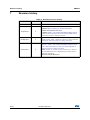
4
Updated: Section 2.1: Hardware installation (Windows
platforms), Table 2: List of supported MEMS adapter boards,
Table 4: Returned values for *start command, and Table 5:
Returned values for *debug command
Added: Section 2.2.2: DFU on Linux, Section 2.2.3: DFU on
Mac OS, and Section 4.2.8: Digital output humidity sensor:
supported commands
Removed: STEVAL-MKI109V1
03-Nov-2014
38/39
Changes
DocID017768 Rev 4
UM0979
IMPORTANT NOTICE – PLEASE READ CAREFULLY
STMicroelectronics NV and its subsidiaries (“ST”) reserve the right to make changes, corrections, enhancements, modifications, and
improvements to ST products and/or to this document at any time without notice. Purchasers should obtain the latest relevant information on
ST products before placing orders. ST products are sold pursuant to ST’s terms and conditions of sale in place at the time of order
acknowledgement.
Purchasers are solely responsible for the choice, selection, and use of ST products and ST assumes no liability for application assistance or
the design of Purchasers’ products.
No license, express or implied, to any intellectual property right is granted by ST herein.
Resale of ST products with provisions different from the information set forth herein shall void any warranty granted by ST for such product.
ST and the ST logo are trademarks of ST. All other product or service names are the property of their respective owners.
Information in this document supersedes and replaces information previously supplied in any prior versions of this document.
© 2014 STMicroelectronics – All rights reserved
DocID017768 Rev 4
39/39
39