1
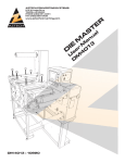
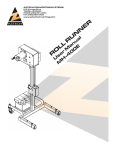
AZTECH CONVERTING SYSTEMS
212 W Lodge Drive
TEMPE, AZ 85283
PHONE (480) 951-8351
FAX (480) 998-5409
www.aztechconverting.com
S
IE
R al
E nu
S
Rer M
a
Ss
U
Rev. 1.1
2015
AZTECH CONVERTING SYSTEMS
SR-SERIES
USER MANUAL
TABLE OF CONTENTS
SECTION 1: GENERAL INFORMATION
1-10
SECTION 2: MACHINE INSTALLATION
10-11
SECTION 3: MACHINE SETUP
12-20
SECTION 4: MACHINE OPERATION
21-37
SECTION 5: MAINTENANCE
38-39
SECTION 6: SATION DETAIL
40-51
SECTION 7: TROUBLESHOOTING
52
SECTION 8: WARRANTIES AND SERVICE
53
AZTECH CONVERTING SYSTEMS
SR-SERIES
USER MANUAL
Section 1: General Information
1-1: Introduction
The AZTECH SR-Series Slitter/Rewind Inspector is available in 10 inch (25.4 cm), 13 inch (33.02
cm), 16 inch (40.64 cm), and 18 inch (45.72 cm) widths, and with either single or dual
rewind spindles. The SR-Series is designed to be highly productive and versatile, and simple to
operate, maintain, or repair with its electronic tension control and clutch-less design. Before operating your new SR-Series, fully read and understand this manual. Following the procedures outlined
in this manual will help assure maximum performance. Keeping your machine properly set-up and
maintained will assure years of productive and satisfactory service.
1-2: Machine Information and Specifications
Up to 750 FPM
process speed
(JOB DEPENDANT)
UNIT
RO
MAC NICS®
v5
HINE
INTE 70 PLC
RFA
CE
30” UNWIND CAPACITY
(40” at reduced speed)
B
WE
10” TH
WID
1 HP DC
MOTORS, REWIND
AND MAIN DRIVE
(2HP NIP OPTION)
30” REWIND CAPACITY
24” (DUAL ARBOR)
(BSR 1X SHOWN)
1
AZTECH CONVERTING SYSTEMS
SR-SERIES
USER MANUAL
FRONT LAYOUT
BSR SINGLE ARBOR
2
Rev 1.1
AZTECH CONVERTING SYSTEMS
SR-SERIES
USER MANUAL
SIDE LAYOUT
DIM
ENS
IO
SPE N MAY
CIFI
ED P CHANG
E
ROC
ESS BASED
ON
WID
TH
ALLOW AT LEAST 3 FEET
OF WORKING CLEARANCE
AROUND THE PERIMETER
OF THE MACHINE
3
AZTECH CONVERTING SYSTEMS
SR-SERIES
USER MANUAL
SIDE LAYOUT
DIM
ENS
IO
SPE N MAY
CIFI
ED P CHANG
E
ROC
ESS BASED
ON
WID
TH
4
Rev 1.1
AZTECH CONVERTING SYSTEMS
SR-SERIES
USER MANUAL
FRONT LAYOUT
BSR DUAL ARBOR
5
AZTECH CONVERTING SYSTEMS
SR-SERIES
USER MANUAL
SIDE LAYOUT
DIM
ENS
IO
SPE N MAY
CIFI
ED P CHANG
E
ROC
ESS BASED
ON
WID
TH
6
Rev 1.1
AZTECH CONVERTING SYSTEMS
SR-SERIES
USER MANUAL
FRONT LAYOUT
ISR SINGLE ARBOR
7
AZTECH CONVERTING SYSTEMS
SR-SERIES
USER MANUAL
SIDE LAYOUT
DIM
ENS
IO
SPE N MAY
CIFI
ED P CHANG
E
ROC
ESS BASED
ON
WID
TH
8
Rev 1.1
AZTECH CONVERTING SYSTEMS
SR-SERIES
USER MANUAL
FRONT LAYOUT
ISR DUAL ARBOR
9
AZTECH CONVERTING SYSTEMS
SR-SERIES
USER MANUAL
1-4: Safety
The SR-Series Slitter/Rewinder is designed to operate at high rates of
speed, employing rollers, gears, pulleys, and other moving parts. Where possible, guards are provided to protect operator from injury. Operators must keep their hands clear of the machine when it
is in operation. Making all operators aware of potential safety hazards will help minimize any chances of operator injury.
Section 2: Machine Installation
2-1: Preparation
It is important that your SR-Series Slitter/Rewinder be situated on solid and level ground. Make
sure that site allows for access to machine from all 4 sides. If the machine is placed on unstable or
un-level ground, it may tip over risking damage or serious personal injury.
2-2: Un-crating Machine
To avoid damage to your new SR-Series Slitter/Rewinder, first remove the cover by removing all
screws, then remove one of the 2 long side panels to expose machine. Remove all 4 lag bolts
which hold the machine to the base. Remove all boxes and parts inside crate.
2-3: Removal and Positioning
It is critical that the SR-Series Slitter/Rewinder be removed from the crate using a fork lift, making
sure that the forks fit directly inside the 2 slots at base of the machine. Lift and remove from crate,
and if equipped with adjustable feet, thread all 4 feet into threaded holes at machine’s base, and
lower into desired position. Machine may be leveled by turning adjustable feet until level.
2-4: Electrical and Pneumatic Connections
ELECTRICAL CONNECTIONS: Your SR-Series Slitter/Rewinder uses a power supply of 220 volts,
20 amps AC. Improper connections or mishandling may cause serious personal injury. AZTECH
highly recommends that electrical service be
performed only by a qualified electrician.
Electrical connection to the machine is performed
by bringing electrical service to the electrical box
at the back of the machine and making connections as shown.
20A 220VAC
SINGLE PHASE
TO DISCONNECT
10
Rev 1.1
AZTECH CONVERTING SYSTEMS
SR-SERIES
USER MANUAL
PNEUMATIC CONNECTIONS: Although
your machine has been thoroughly tested
before shipment, connections on occasion may loosen during shipment. Visually
inspect all pneumatic to assure that each
is fitted securely. Connect airline to the
pneumatic control panel at the back of
the machine (see figure 2-B), and listen
for any air leaks that may exist. Check all
switches by switching back and forth from
on and off to make sure they are operating properly.
90PSI INCOMING HP AIR
NOTE: Red lines on air dials indicate proper default settings.
2-5: Testing Before Operation
Make sure the area around your machine is clear of any objects which may impair the machine.
Also inspect and make sure all belts, pulleys, rollers, and spindles are free and clear of any
objects which may impede operation, and risk machine damage. Before threading your machine,
accelerate and decelerate your machine through a full range of speeds, and make sure acceleration is smooth and free of any unnatural sounds or movements. Using control switches, switch
Unwind and Rewind Spindle(s) from on and off positions making sure the pneumatic system is
performing properly. Then turn power on, run machine at low speed to assure machine is working
properly. Then with speed set at maximum setting, press the stop button to assure that the brake is
working properly.
11
AZTECH CONVERTING SYSTEMS
SR-SERIES
USER MANUAL
Section 3: Machine Setup
3-1 Webbing the Machine
Proper webbing of your SR-Series Slitter/Rewinder is vital to optimal machine performance. The
following pages illustrate the proper ways to thread your machine for various substrates. Any improper webbing of the machine may cause tension problems that will impede operation.
To web the machine:
1. Turn unwind arbor switch to “DEFLATE”
position.
2. Assure that the rewind and unwind
switches on main panel are in the
“OFF” position
3. Assure that both splice-table clamps
are released into the up position.
4. Assure that the pneumatic nip roll is
disengaged in the up position.
5. Assure that the slitting blades are
disengaged. BE SURE TO USE
CAUTION WHEN NEAR SLITTING
BLADES AS THEY ARE EXTREMELY
SHARP AND MAY CAUSE SERIOUS INJURY.
6. Load roll onto unwind spindle and
carefully thread the web through the
machine making sure to follow web
paths on the following page.
12
ARBOR LOCK
SWITCHES
Rev 1.1
AZTECH CONVERTING SYSTEMS
SR-SERIES
USER MANUAL
SR Series Web Path(s)
BSR Single Arbor
Proper webbing of your SR-Series Inspection Rewinder is vital to optimal machine performance.
Any improper webbing of the machine may cause tension problems that will impede operation.
NOTE: Web paths are shown in OVERWIND configuration and through optional inspection towers.
13
AZTECH CONVERTING SYSTEMS
SR-SERIES
USER MANUAL
BSR Dual Arbor
14
Rev 1.1
AZTECH CONVERTING SYSTEMS
SR-SERIES
USER MANUAL
ISR Single Arbor
15
AZTECH CONVERTING SYSTEMS
SR-SERIES
USER MANUAL
ISR Dual Arbor
16
Rev 1.1
AZTECH CONVERTING SYSTEMS
SR-SERIES
USER MANUAL
3-2 Web Guide Setup
AUTOMATIC
SERVO CENTER
The web guide is located in the center of
the machine between the unwind and rewind stations. After webbing the machine,
set the web by doing the following:
Setting the Web Guide:
1. Press the “SERVO-CENTER” button on the
front of the web guide.
2. Align the sensor with the inside edge of the
web. For fine alignment adjustment, turn
knob on outside of web guide.
3. Jog the machine briefly to assure that the
web is moving smoothly.
4. Press the “AUTOMATIC” button which
will engage the sensor and allow the web
guide to adjust itself to the movement of
the web.
5. For more specific instructions about the
features of the web guide, refer to the Accu-Web manual included with this manual.
COARSE
SENSOR
POSITIONING
FINE
SENSOR
POSITIONING
3-3 Nip Roll Operation
The Nip Roll is pneumatically controlled using control switch (see
figure 3-E) and must be in the down position while machine is
running, and in the up position when threading machine.
17
AZTECH CONVERTING SYSTEMS
SR-SERIES
USER MANUAL
3-4: Splice Table Operation
The splice table on your SR-Series is located just above the Unwind Station, just after the optional
Inspection Tower. To operate the Splice Table, simply follow the following steps:
L
E
NN
A
I
TT
I
SL
TURN TO
ADJUST TABLE
POSITION
NG
CH
WEB CLAMP
SWITCHES
1. Turn off machine and engage both web clamp switches.
2. Using a razor blade, carefully cut the web along the slicing channel. Disengage the clamp nearest the unwind station. Be sure to leave the other clamp engaged.
3. After waste has been removed, pull through new web, carefully align with web, and lower the
handle to hold.
4. Again using a razor blade, cut the web, discard waste, pull tape under webs, fold to secure and
cut tape.
5. Disengage both switches to release web clamps.
18
Rev 1.1
AZTECH CONVERTING SYSTEMS
SR-SERIES
USER MANUAL
TURN TO UNLOCK
SLITTER
3-5: ROTARY SHEAR SET-UP
Step 1 Set lower blades for
desired Slit-widths and tighten
set-screws, making sure upper
blades are up and not in lock
position.
Step 2 Lower upper blade
assembly by turning handle
counter-clockwise and snap
into lock position, making sure
that the upper blades are clear
of lower blades to avoid blade
damage.
STOP/JOG
BUTTON
NIP
LOCK
Step 3 Gently slide upper
blade(s) into cutting position
flush against the lower blade(s)
by pushing on both sides of the
blade to avoid wobble. Hold upper blade against lower blade
and tighten set-screw.
LATERAL SHEAR
ADJUSTMENT
TIGHTEN SET SCREWS
TO LOCK BLADES
19
AZTECH CONVERTING SYSTEMS
SR-SERIES
USER MANUAL
E-STOP
MACHINE
LOOSEN SET
SCREW HERE
(BSR SHOWN)
3-6: Changing Rewind Spindle
Your SR-Series Slitter/Rewind Inspector is
equipped with Convertech pneumatically
inflatable rewind spindles. These spindles are
easily removed by loosening the hex-screw
at the machine side and pulling away from
machine. To insert new spindle, simply insert
spindle into rewind station and tighten hexscrew firmly.
(ISR SHOWN)
20
CAUTION: Utilizing Rewind Spindles less
than 1.5” in diameter require the use of
Outboard Support Apparatus which is NOT
included in the standard equipment. Operating the machine without the support
apparatus and with spindles less than 1.5”
may result in serious injury.
Rev 1.1
AZTECH CONVERTING SYSTEMS
SR-SERIES
USER MANUAL
Section 4: Machine Operation
4-1 Operator Control Layout
OVER/
UNDER-WIND
AUX.
SWITCH
SPEED
KNOB
E-STOP
STOP/JOG
PB
START PB
REWIND
SWITCHES,
GAUGE AND
REGULATOR
TOUCH
SCREEN
PLC
21
AZTECH CONVERTING SYSTEMS
SR-SERIES
USER MANUAL
SPLICE CLAMPS
WASTE WIND
CONTROLS
E-STOP
22
STOP/JOG
PB
START PB
Rev 1.1
AZTECH CONVERTING SYSTEMS
SR-SERIES
USER MANUAL
OVER/
UNDER-WIND
SPLICE CLAMPS
SPEED
KNOB
E-STOP
TOUCH
SCREEN
PLC
STOP/JOG
PB
START PB
ARBOR LOCKS,
AND UNWID
REGULATOR
23
AZTECH CONVERTING SYSTEMS
SR-SERIES
USER MANUAL
4-2: PLC OPERATION
4-2-1: THE MAIN MENU
MENU JUMPS
On power-up of the machine, the PLC will boot. This is analogous to a home
PC booting. It can be expected to take between 30 and 60 seconds.
LANGUAGE SELECT
When the PLC has finished booting, the MAIN MENU will be displayed.
When the MAIN MENU is displayed, the PLC will lock-out the operator buttons
and the machine will not run.
24
Rev 1.1
AZTECH CONVERTING SYSTEMS
SR-SERIES
USER MANUAL
4-2-2: THE RUN MANUAL SECTION
MACHINE STATUS
While in the MANUAL RUN section of the HMI, the user has access to the
basic controls for machine operation and status. The user controls will operate the machine to parameters set here while in the MANUAL RUN section of
the HMI.
MENU JUMPS
Basic machine status is shown by the line of small LED icons in the center
right of the screen. Green is generally used to indicate ON or ACTIVE and red
is used to illustrate OFF or DISABLED.
25
AZTECH CONVERTING SYSTEMS
SR-SERIES
USER MANUAL
COUNTER SETUP
SET
COUNT
COUNT
PROGRESS
The current
state of the
counter is
shown by the
percentage
scale bar on
the right hand
side of the
screen. The
fill is based on
% of the set
count. The
precise count
is shown in
green on the
lower left of
the counter
bar. Pressing
the RESET
button clears the count and toggling the COUNTER I/O switch will prevent the
counter from incrementing.
The counter preset points can be modified by accessing the COUNTER SETUP
screen from the RUN MANUAL screen. The buttons for this and other screenjumps are displayed as a banner on the bottom of the RUN MANUAL screen.
These jumps will also access the re-wind functions and return the user to the
MAIN MENU.
While in the setup for the counter, the user programs the SET COUNT and the
SLOWDOWN point. While the counter is on, the machine will run at set speed
until the SLOWDOWN count is reached. The machine will then travel at JOG
speed until the SET COUNT is reached. Both points are programmed by touching the number. Once pressed, a dialogue will open to allow the user to edit the
number.
If the slowdown count is set higher than the SET COUNT, the machine will
not enter slowdown when running. If the SET COUNT is set below the
SLOWDOWN count, the machine will run the whole job slow.
CURRENT #
UNITS
ON/OFF
RESET
26
Rev 1.1
AZTECH CONVERTING SYSTEMS
SR-SERIES
USER MANUAL
The button below the number entry boxes
is used to toggle between DISTANCE and
LABEL count. Toggling the button changes
its display from “DISTANCE” to “LABELS”
and vice versa. It also toggles a relay within
the main cabinet that switches between sensor inputs to the counter on the PLC. The
state of this selection is listed on the RUN screen next to the counter. While in DISTANCE mode, the option is given to count in Inches, Feet, Yards and Meters.
Pressing the RUN MENU button on the bottom of the screen returns to the RUN MENU. Alternatively, the RW SETUP
and OSCILLATOR setup may be accessed from the COUNTER SCREEN.
RUN MODE
In the upper-right corner of the COUNT AND REWIND SETUPS is a STATUS indicator. This is to inform the user of the machine’s state while out
of the RUN MENU. Green indicates the machine is in RUN MODE, yellow
JOG and red indicates that the machine is STOPPED.
Also on the RUN MANUAL
STOP MODE screen is a rate meter in the
JOG MODE
(SHOWN OFF) upper right corner. This displays
(SHOWN OFF)
approximate FPM as counted
by a wheel in contact with an idler roller on the post-process side of the NIP
assembly. If the gauge is shaky or inaccurate, check to make sure that the
web is not slipping on the idler roller.
27
AZTECH CONVERTING SYSTEMS
SR-SERIES
USER MANUAL
REWIND SETUP
Setup for the REWIND arbors is also
accessed from the RUN MANUAL
screen. Using the menu jumps, the
RW setup screen is loaded. In the
REWIND SETUP screen, the torque
is set for the UPPER and LOWER
rewind, the UPPER and LOWER
rewind are ENABLE/DISABLED and
TORQUE COMPENSATION may be
engaged.
Pressing the motor icon for the selected arbor will ENABLE/DISABLE
the arbor. A green icon indicates the
arbor in ENABLED. A red icon indicates the arbor is DISABLED.
The number box may be pressed to
open a dialogue to edit the set torque.
Set torque is 0-100% scale.
TORQUE COMPENSATION adds 30% torque linearly up to
30” in roll diameter, if available.
The large LED icon ENABLES/DISABLES the torque compensation.
REWIND
ENABLE
Roll diameter calculations are also related to WEB BREAK.
See the section on WEB BREAK for more information.
% TORQUE
SETTING
28
TORQUE
COMP
Rev 1.1
AZTECH CONVERTING SYSTEMS
SR-SERIES
USER MANUAL
ACCESSORY SETUP
The SR series machine may be
equipped with a vision inspection system or a web oscillation system produced by one of AZTECH’s production affiliates. This section will detail
the HMI operation of these features.
If your machine is not equipped with
either of these features, their associated controls will not be present on
the screen.
The vision inspection system uses an
optical camera to compare labels as
they travel on the web to a “golden”
sample. If the machine detects a
label that is flawed compared to the
golden, the system sends a signal
to the machine to JOG as long as
the signal is HIGH. By adjusting the
length of this slowdown signal on the
vision inspection system, the machine
can be made to stop the flawed label
on the inspection table. Please refer
to the manual for the vision inspection system for more information on the vision system and please refer to AZTECH
DWG 20298 for more details on the interface between the machine and vision system.
The machine may also be equipped with a web oscillation feature that is driven by the web guide. This oscillation can
be used for the prevention of gauge bands when working with materials that have non-uniform thickness.
When the oscillation is active, the SR will send a signal to the web guide to oscillate the web as long as the machine is
in RUN or JOG mode, i.e. the web is moving. The degree of this oscillation is controlled by setting parameters on the
web guide. Please refer to AccuWeb’s manual for more details.
The PLC functions pertaining to the WEB OSCILLATION system may be shut off on the HMI in the RUN screens.
29
AZTECH CONVERTING SYSTEMS
SR-SERIES
USER MANUAL
COUNTER SETUP
MAIN
MENU
WRITE
EDITS
REWIND
SETUP
30
Rev 1.1
AZTECH CONVERTING SYSTEMS
SR-SERIES
USER MANUAL
4-2-4: RECIPE EDITOR
The recipe editor is a table program for entering and storing job data. The job parameters such as run speed and rewind tension are stored in the editor and then recalled in the RUN RECIPE routine and used to run jobs.
While in the RECIPE EDITOR, the operator buttons on the machine will be locked out and will not allow the machine to
run. This is a safety feature.
The RECIPE EDITOR is used to change the stored parameters of the jobs. It can be accessed from either the MAIN
MENU or the RUN RECIPE section.
Edits are made by pressing the attributes. Once a change has been made, the SAVE CHANGES button must be
pressed or the new information will not be stored.
The REWIND TENSIONS and FPM have set ranges. Tensions may be entered 0-100 and FPM may be entered 0-750.
If the HMI will not take a value, it is possible that the value is out of range. Try re-entering within this range.
The UP and DOWN arrows are used to navigate the table one row at a time. The HOME ROW button will load the
begging of the table.
Once edits are saved, the recipes may be used to run jobs in the RUN RECIPES section of the HMI.
A table view is provided for ease
of recipe navigation. Pressing the
RECP. EDIT button will allow the user
to edit the middle row.
31
AZTECH CONVERTING SYSTEMS
SR-SERIES
USER MANUAL
4-2-5: RUN RECIPES
The RUN RECIPES section of the HMI is used to execute job
programs saved in the RECIPE EDITOR section.
From the MAIN MENU, the RUN RECIPES screen is loaded when
the RUN RECIPES button is pressed.
The current loaded recipe is shown in the RECIPE name box.
Recipes may be loaded using the up and down arrows under the
RECIPE name box.
NOTE: If edits are made to the current loaded recipe, the job must
be reloaded using the arrow buttons to update.
The recipe details will be shown in green in the center of the
screen. Take note of which rewind arbors are engaged. Running web to the wrong arbor will have negative results.
Below the recipe details is
a counter bar to indicate %
of the run completed. The
operation of this bar is similar to the completion bar in
section 4-2-3. To the right of the bar, the current process count is displayed. The toggle switch to the right may be used
to stop the counter at its current count and run material without incrementing the counter, for example, to remove bad
material.
At the completion of a run, the progress bar will show 100%
completion and the machine will stop. At this point, the START
button will not re-start the machine. This is caused be the
machine registering a complete run. The job may be cleared by
pressing the RESET JOB button. At this point, the progress bar
will be empty and the machine is ready for a second run.
The machine will not start a job if the web is still moving. The machine will indicate if it is ready to start a job by displaying a green icon on the lower right corner of the HMI.
32
Rev 1.1
AZTECH CONVERTING SYSTEMS
SR-SERIES
USER MANUAL
RECIPE
SELECT
MAIN
MENU
RECIPE PARAMETERS
READY TO
RUN LED
RESET
JOB
33
AZTECH CONVERTING SYSTEMS
SR-SERIES
USER MANUAL
4-2-6: WEB BREAK
The SR Series is equipped with a safety routine to stop
the machine in the event of web break. (Loss of material
moving through the machine.)
The WEB BREAK routine relies on computing the diameter of the rewind roll by comparing the RPMs of the
rewind arbor to the linear measurement of web moving
through the nip section.
The linear measurement of web is taken from a counter wheel in contact with an idler roller located in the
post-process section of the nip assembly. This is a 64
count per rev wheel, and with a diameter of 2.547”, it
registered 1/8” travel for every encoder pulse.
The RPM measurement of the arbor is taken by a similar
encoder mounted inside the machine. This encoder
NIP ENCODER
registers 64 pulses for every revolution of the rewind arbor.
Consequently, the amount of material measured per-pulse
increases with roll diameter.
From these two frequencies, we have:
(NIP Hz / RW Hz) = ROLL DIAMETER / 2.547
Once the machine is moving, a register containing the
last 5 values of calculated roll diameter is maintained. If
the average of this register is less than 2” (minimum arbor
diameter) a web break is triggered. If the diameter is seen
to decrease during the run, a web break is triggered. (The
rewind roll should never get smaller...)
REWIND ENCODER
Due to the nature of these calculations, various sources of
error may result in false web-breaks.
The most common source of error is slipping on the NIP encoder. When the material slips on the NIP encoder, the
diameter is seen to be artificially small. This will cause repeated web-breaks and a machine that will seem to not want
to run a job.
If this happens, check the contact of the counter wheel to the idle roll to make sure the surface is clean. Secondly,
check the tension to make sure the material has adequate “grab” on the idle roller.
34
Rev 1.1
AZTECH CONVERTING SYSTEMS
SR-SERIES
USER MANUAL
4-2-7: PLC RESOURCES
The PLC is manufactured by Unitronics.
866-666-6033
[email protected]
www.unitronics.com
The PLC is programmed using:
VisiLogic 9.7.44
VisiLogic is available for free download at www.
unitronics.com. Consult the Unitroncis website
for technical details on the PLC.
Motor drives are made by K&B Electronics
Spares, technical support and service are provided by:
AZTECH Converting Systems Inc
212 W Lodge St.
Phoenix, AZ 85283
[email protected]
(800) 829 - 8351
35
AZTECH CONVERTING SYSTEMS
SR-SERIES
USER MANUAL
4-5: Rewinding Large Diameter Rolls
When rewinding large diameter rolls with the SR-Series, it is critical to
steadily increase tension as the roll diameter increases and minimize trapped air in the finished
rolls. It is recommended that the operator set the rewind tension at a low setting at the beginning of
the roll, and gradually increase the rewind tension by either manuallly entering larger numbers into
the re-wind tension field on the PLC as the diameter increases or by selecting the diameter compensation option.
To achieve consistent large-diameter rolls, it is critical to use the top-rider assembly to avoid trapping air. If your SR-Series machines not equipped with a top-rider, they are easily installable and
may be purchased by contacting AZTECH Machinery.
4-6 Increasing Web Speed
The comes with default settings (see figure 4-D) that allow for peak performance for slitting and
rewinding various substrates and roll sizes. If you wish to increase the web speed, you may at your
discretion, switch over the rewind belt(s) which will change the ratio of web speed as follows:
1. Open or remove rewind panel.
2. Loosen handle by turning counterclockwise and pulling belt-tightener-arm
outward.
3. With belt loose, change over to opposite pulleys.
4. Push belt-tightener arm inward and
tighten handle clock-wise.
5. Close or replace rewind panel.
Handle locks
tensioner
Remove panel to
access belt.
36
Rev 1.1
AZTECH CONVERTING SYSTEMS
SR-SERIES
USER MANUAL
LOW-SPEED
RATIO
HIGH-SPEED
RATIO
CAUTION: BY SWITCHING BELTS TO INCREASE WEB SPEED, THE SR WILL TAKE LONGER
TO STOP, ESPECIALLY WHEN RUNNING AT HIGH SPEED WITH A LARGE OR HEAVY UNWIND ROLL. IF DIFFICULTIES OCCUR, SWITCH BELTS BACK TO THE DEFAULT SETTING.
37
AZTECH CONVERTING SYSTEMS
SR-SERIES
USER MANUAL
Section 5: Maintenance
5-1: Maintenance
Your SR-Series Slitter Rewinder is rigidly constructed to provide your company years of productivity, while being relatively maintenance free. However, to aid in assuring maximum performance and
longevity, the occasional following maintenance is recommended:
• Apply a small amount of clear silicone grease to all gears.
• Inspect belts for tightness and wear and tighten or replace as necessary.
• Clean rubber nip roll using a rag and denatured alcohol. DO NOT USE A
RAZOR BLADE OR ABRASIVE PAD AS THEY WILL CAUSE IRREPARABLE DAMAGE TO THE
ROLL SURFACE.
• Replace any of the slitting blades if they are noticeably chipped or damaged, or if you notice excess
slitting dust or if the blades are not cutting cleanly.
• Clean counter wheel (see figure 5-A) by blowing
with air nozzle assuring all holes are free of dust or
debris.
38
Rev 1.1
AZTECH CONVERTING SYSTEMS
SR-SERIES
USER MANUAL
5-2: Adjusting the Unwind Brake
The unwind brake on the may require occasional adjustment. To adjust the brake,
follow these simple instructions:
Remove panel
to access
brake
1. Remove unwind station cover.
2. Raise and hold dancer arm into a level
position and while holding in level
position, spin the unwind spindle with
other hand. The unwind spindle should
spin while feeling some resistance. If
the spindle is free moving or unable to
move, adjust brake by loosening nut
and lock nut on backside of the unwind
station, adjust accordingly, tighten nut
and re-check. Repeat this procedure
until properly adjusted.
3. Replace unwind station cover.
Tighten/Loosen
to adjust brake
tension
Rem
ove
to ac panel
ces
brak s
e
39
AZTECH CONVERTING SYSTEMS
SR-SERIES
USER MANUAL
Section 6: Station Detail
40
Rev 1.1
AZTECH CONVERTING SYSTEMS
SR-SERIES
USER MANUAL
41
AZTECH CONVERTING SYSTEMS
SR-SERIES
USER MANUAL
Section 6: Station Detail
42
Rev 1.1
AZTECH CONVERTING SYSTEMS
SR-SERIES
USER MANUAL
43
AZTECH CONVERTING SYSTEMS
SR-SERIES
USER MANUAL
Section 6: Station Detail
44
Rev 1.1
AZTECH CONVERTING SYSTEMS
SR-SERIES
USER MANUAL
45
AZTECH CONVERTING SYSTEMS
SR-SERIES
USER MANUAL
Electrical Details
20298 Main Enclosure
20713 Operator Enclosure
20421 Waste Rewind Enclosure (Option)
46
Rev 1.1
AZTECH CONVERTING SYSTEMS
SR-SERIES
USER MANUAL
20298 pg. 1
Main Enclosure
47
AZTECH CONVERTING SYSTEMS
SR-SERIES
USER MANUAL
20298 pg. 2
Main Enclosure
48
Rev 1.1
AZTECH CONVERTING SYSTEMS
SR-SERIES
USER MANUAL
20298 pg. 3
Main Enclosure
49
AZTECH CONVERTING SYSTEMS
SR-SERIES
USER MANUAL
20713
Operator Enclosure
50
Rev 1.1
AZTECH CONVERTING SYSTEMS
SR-SERIES
USER MANUAL
20421
WRW Enclosure
51
AZTECH CONVERTING SYSTEMS
SR-SERIES
USER MANUAL
Section 7: Troubleshooting
7-1: Why doesn’t the machine turn on?
First check to make sure that the main power switch on the back electrical panel is turned on. Then
make sure that the emergency stop button on control panel is
disengaged.
7-2: The counter is not counting accurately.
Make sure the counter wheel below the web guide is riding against the idler roller, and is
free of dust or debris (see chapter 5) and is not visibly damaged.
7-3: Why is the counter not counting inches?
Make sure that the counter sensor below the web guide is flashing red which assures that it is properly connected to the machine. Be sure that the setting on the PLC is “Distance”.
7-4: Why is the counter not counting labels?
If your machine is equipped with the optional label counter and is not doing so, after assuring that
the counter sensor below the web guide is flashing red which assures
that it is properly connected, assure that the PLC is set to “LABELS”.
7-5: Why isn’t the end-of-roll sensor working?
If your is equipped with the optional end-of-roll shut-down and it is not shutting down the machine
when the unwind roll is near the end, or if it is shutting down prematurely, perform the following:
1. Assure that the light on the sensor (see figure 7-B)
located near the unwind spindle is illuminated.
2. If not illuminated, check wiring for proper connections or damage. If wiring is set up properly, the
sensor may need to be replaced.
3. If illuminated, the sensor may be in need of adjustment. If the machine is shutting down prematurely, the sensor needs to be moved closer to the
unwind spindle, where if it is not shutting down
the machine at all, the sensor needs to be moved
away from the unwind spindle. To adjust the sensor, simply loosen the set screw, slide bracket in
either direction, and re-tighten.
Set Screw
Adjust Sensor
Height
52
Rev 1.1
AZTECH CONVERTING SYSTEMS
SR-SERIES
USER MANUAL
Section 8: Warranties and Service
8-1: Warranties & Provisions
WARRANTIES: All equipment manufactured and sold by AZTECH Converting Systems (Seller) is
warranted to be free of defective materials and workmanship under normal use and service for a
period of one (1) year from the date of delivery to Buyer's premises. All commercial components not
manufactured by Seller carry the original manufacturer's warranty. At Seller's discretion, Seller may
provide on-site warranty service for a period of ninety (90) days from the aforementioned date.
REMEDIES If within the Warranty Period any such Equipment is proven to Seller's satisfaction to
be defective in either material or workmanship, Seller, at its sole discretion, shall (a) repair or replace defective parts on the Equipment at Seller's cost, or (b) grant a reasonable allowance on
account of such a breach. If within the Warranty Period the Seller receives notice from Buyer of
defects in parts or materials. Seller will ship (ground, prepaid) replacement parts) and invoice Buyer
for the full cost of the replacement parts). Buyer will receive a Return Authorization (RA) from seller,
and return defective parts or materials to Seller, who at its sole discretion shall determine whether
defective parts or materials are or are not subject to exclusion from this warranty as provided herein. Any defective parts or material not excluded from the Warranty Period will then be fully credited
to Buyer.
EXCLUSIONS
THE FOLLOWING ITEMS ARE EXCLUDED FROM THIS WARRANTY:
• Defects or damage caused by careless or improper use.
• Parts that need periodic replacement from wear during normal operation.
• Routine maintenance and adjustment.
• Failure or damage caused by improper
installation or inadequate maintenance by Buyer.
• Failure or damage caused by equipment modifications by Buyer.
• Equipment damage resulting from an accident, or abnormal conditions of operation.
DISCLAIMER OR WARRANTY
NO OTHER WARRANTY IS EXPRESSED OR IMPLIED INCLUDING WARRANTIES OF MERCHANTABILITY AND FITNESS FOR ANY PARTICULAR PURPOSE. SELLER IS NOT LIABLE
FOR INCIDENTAL OR CONSEQUENTIAL DAMAGE SUCH AS, BUT NOT LIMITED TO LOSS IN
PROFITS, LOSS OF USE OF EQUIPMENT, OR INCREASED IN OPERATING COSTS OR EXPENSES.
8-2: Technical Service
In the event that your machine is not functioning properly or if you have any technical questions,
an AZTECH Technical Service representative is available to assist you. Contact information is as
follows:
Phone:
1-480-951-8351
1-800-829-8351
Fax:
1-480-998-5409
E-Mail:
[email protected]
53