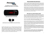
1
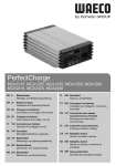
Project54 Hardware Manual
Version 3.0
Consolidated Advanced Technologies for
Law Enforcement Program (CATlab)
University of New Hampshire – Durham, NH 03824
603.862.4518 | www.catlab.unh.edu | [email protected]
© 2005 University of New Hampshire. All Rights Reserved.
Project54 Hardware Manual
Introduction – page 1
Preface
Project54 has two main goals; first, it aims to improve the ability of police to collect and
interpret data in, as well as exchange data between mobile police units. Second, it aims to
provide a seamless way to integrate the controls of all of the equipment within a police
cruiser.
This document is a comprehensive instruction set for the assembly and implementation of
the Project54 system in a police car. The system was developed at the University of New
Hampshire’s (UNH) Consolidated Advanced Technologies for Law Enforcement Program
(CATlab). Within this document are detailed instructions for the installation of a Project54
system into any police cruiser. Included also are explicit instructions for a wide range of
police vehicles including the Ford Crown Victoria and Chevrolet Impala.
On the following page, Figure 1 shows some of the critical devices incorporated into the
Project54 system. Their relative placements in the cruiser are depicted to help an installer
with equipment placement and to know which areas of the cruiser he/she will be primarily
working on.
PC Requirements
In order for the Project54 system to function to its full potential, the computer system used
must meet certain minimum requirements. The computer must run either Windows 2000 or
Windows XP as an operating system; it must have a minimum of 256 MB of RAM, a
minimum of 12 GB of total disk space, a touch-screen display, and at least one serial or
USB port. It also must have at least a Pentium II with a 500 MHz processor or faster.
If the car is equipped with a computer system already, the Project54 software can be added
to the computer as long as it meets the minimum specifications. This will not affect the
computer’s operation with existing third-party software. In addition to laptops and tablet
computers, the Project54 system can also be supported by a compact “embedded” style
computer which meets the system requirements outlined above.
Supported Devices
The Project54 system supports a wide array of public safety devices, from video systems to
light bars to radios; new equipment is always being integrated. Most devices which are over
10 years old are not supported directly as they lack external control interfaces.
Some devices require an extra kit of parts for complete Project54 operation, so often times
the manufacturer will include this kit along with the new equipment. For this reason, make
sure, when ordering new vehicle equipment, to tell the sales person that it will connect to
Project54. Any equipment that is not part of the standard package is noted on the device
installation sheet.
project54.unh.edu
Copyright © 2005 University of New Hampshire
[email protected]
Introduction – page 2
Figure 1 – Project 54 Components
Project54 Hardware Manual
project54.unh.edu
Copyright © 2005 University of New Hampshire
[email protected]
Project54 Hardware Manual
Introduction – page 3
Installation Notes
The installation of the Project54 system into a public safety vehicle may be done in one of
two ways – either by adding the system to an existing vehicle installation or by installing new
equipment and Project54 all at once. It is important to note, however, that a fresh vehicle
installation is not required for Project54 to be installed. Since the Project54 system works in
parallel with the standard hardware in the vehicle, it can be simply attached to the
appropriate devices after they are completely installed in the vehicle. This type of “parallel”
connection allows the system to communicate with devices, but does not cause Project54 to
interfere with traditional device operation.
Manual Organization
The Project54 Hardware Manual is divided into modular sections which are device-specific.
The following pages contain detailed information on the installation of the exact equipment
in the cruiser. If new equipment is added or old devices are replaced in the future, please
notify Project54 and documentation will be provided to add to this binder for the new
devices.
To better organize this modular architecture, the manual has been broken down into the
following sections:
II.
1.
2.
3.
4.
5.
6.
7.
8.
9.
IDB Network Installation
Vehicle Configuration
Lights & Siren
Radio
Radar
GPS
Video Recorder
Push-To-Talk System
On-Board Diagnostics
Other
project54.unh.edu
Copyright © 2005 University of New Hampshire
[email protected]
Project54 Hardware Manual
IDB Network Installation
Project54 Hardware Manual
IDB Network – page 1
The IDB Network
The base of the Project54 hardware interface consists of a standards-based network, called
the “Project54 IDB Network”. The vehicle’s equipment (lights, radios, radar, etc…) is
connected to this network via IDB Interface Boxes. The boxes are linked to one another in a
daisy-chain fashion using Category 5 Ethernet cables with RJ45 connectors. Devices can
then connect to the boxes using interface cables with either DB9 or DB25 connectors
between the box and the device itself. The first box in the network chain is always a
computer box which is used to connect the computer system to the IDB network. Devices
are then connected to their specific IDB Interface Boxes as the chain continues. The
Project54 IDB Network architecture is illustrated in the figure below:
Figure 1 - Project54 IDB Network Architecture
IDB Boxes
The IDB boxes are the interfaces which translate between the vehicle’s devices and the IDB
network. These boxes are necessary because not every device in a police car uses the
same communication standards. The use of these boxes in conjunction with the IDB
network allow for all of the in-car devices to be controlled through the same communication
medium by a single device (the computer).
All of the IDB boxes are physically identical except for the computer box. Therefore, all of
the device (non-computer) boxes may be interchanged with one another once a series of
switches within the box are modified. However, boxes are often labeled and have the
switches set by the manufacturer to particular device type. These switches control three
parameters: the box address, the network terminating resistor, and hardware handshaking.
The address switches are what differentiate the boxes from one another, so a lightbar IDB
box will have a different address (and therefore, different switch settings) than the radio IDB
box. The addresses for each device are shown throughout this manual. By having different
addresses for each different device, the Project54 software can communicate directly with
any individual device it chooses.
project54.unh.edu
Copyright © 2005 University of New Hampshire
[email protected]
Project54 Hardware Manual
IDB Network – page 2
Figure 2 - Inside an IDB Box
Figure 2 above shows the view of a version 4 IDB box without its metal case. The red and
white box in the middle houses the DIP switches used to configure the box’s address as well
as the terminating resistor. The following table illustrates what each switch (numbered 1-8)
is for and how it is configured in this diagram.
Switch #
1
2
3
4
5
6
7
8
--
Function
IDB Box Address (LSB)
IDB Box Address
IDB Box Address
IDB Box Address
IDB Box Address (MSB)
Terminating Resistor
Pull-Up Resistor (microphone)
Not Used
Handshaking (blue & white switches)
State (in Picture)
1
1
1
0
1
DISABLED
ENABLED
N/A
DISABLED
Table 1 - IDB Box DIP Switch Map
The address is from MSB to LSB, making this box addressed as “10111”. To convert this
address into a Project54 Hex address, first start by converting the binary address to a base10 number. Now double the value and convert it to hex – this is the box address. Using
Figure 2 as an example, “10111” is “23” in base-10; multiplied by two and converted to hex,
the box address is “2E”. Thus we see that the box is currently configured as a microphone
box. By simply changing the DIP switches, however, this box can be reconfigured to
interface with a different device.
IDB Network Power & Termination
The IDB network is terminated on one end and powered on the other. The power is sourced
from a clean, regulated 12v supply and is applied to one of the RJ45 ports on the computer
IDB box (see Figure 3). The category 5 cable which plugs into this port should have its other
project54.unh.edu
Copyright © 2005 University of New Hampshire
[email protected]
Project54 Hardware Manual
IDB Network – page 3
end stripped of the casing and the blue and green wires twisted together and connected to
the +12v supply. The blue and green striped wires should also be twisted together and
connected to the ground side of the 12v source (see Figure 3). The power is relayed to all
other boxes on the network through the daisy-chain of category 5 cables.
Figure 3 - IDB Power Connections
As for terminating the network, this can be done in any of several ways. The most common
method is to enable DIP Switch 6 inside of the IDB box. However, if the vehicle has GPS
capabilities, the Project54 GPS IDB box comes by default with this resistor enabled. If a
Whelen light bar is being used with their GWAYVA2 Network Gateway, there is a DIP switch
inside of it to enable the terminating resistor. The final method of network terminating is to
insert a terminator plug into the open RJ45 port on the last box in the network (more on
these below). The network must be terminated to ensure that signals moving down the
network do not interfere with one another.
IDB Box Placement
The location of the IDB boxes in the Project54 system is determined solely by the location of
the device they control. The idea is to place the boxes in a convenient spot, close to the
device. In most installations, the boxes are placed in one of two locations: the trunk or in the
front of the car in the console or under the dash. However, placement is flexible and can be
determined by the installer in the specific vehicle. Keep in mind though that while the IDB
boxes are fairly resistant to temperature changes, they are not waterproof, so make sure
they are placed in a dry location.
Cables
The interconnect cabling used in the Project54 system falls into three categories: Category 5
Ethernet cables, 9 pin serial cables (straight through or null-modem), and device-specific
cabling. The Ethernet cables are used to link all of the IDB boxes to one another and also to
apply power to the network, forming the CAN-2B/IDB network. These cables may be
purchased anywhere as long as they meet the FAST Ethernet standard (CAT-5).
project54.unh.edu
Copyright © 2005 University of New Hampshire
[email protected]
Project54 Hardware Manual
IDB Network – page 4
Figure 4 - Example IDB Network
The serial cables come in two versions which are used by Project54, the standard straight
through variety and the null-modem type. Both have 9-pin connectors, but the straight
through cable is used by the computer to go from its serial port (or a USB port using a USBto-Serial adapter) to the computer IDB box. Most devices, however, communicate with the
IDB box through a null-modem cable; in some cases, the manufacturer will supply the cable
to you for the device. The new IDB box design will reverse the roles of the straight through
and null-modem cables. This means that with the new boxes, null-modem cables will
connect the computer to the computer IDB box and straight-through cables will serve as the
device interconnects.
Specialty cables connect devices which do not have standard Project54 interfaces (no DB9
serial port) to an IDB box. In these cases, manufacturers have been setup to provide these
specialty cables so that they are openly-available. Part numbers and manufactures are
listed on the installation sheets for each device.
New IDB Box Design
There is a new design of the IDB boxes which will be deployed shortly. These new boxes no
longer use DIP switches and instead use a software program to change addresses. There is
also no longer an on-board terminating resistor – this has been traded for an external plug
which should be placed in the open port on the last IDB box in the network chain. An
example of the new box is shown below:
Figure 5 - Version 5 IDB Box
project54.unh.edu
Copyright © 2005 University of New Hampshire
[email protected]
Project54 Hardware Manual
1. Vehicle Configuration
Project54 Hardware Manual
2. Lights & Siren
Lights
Manufacturer: Code3
Model: 2100SC (Serial Interface)
page 1/2
August 6, 2007
Device Image
Application Screenshot
Connection Diagram
Special Instructions
1. The blue and violet cabling shown in the connection diagram are all cables provided from Code3. They do
not appear to have part numbers, but the connections at the RLS Expansion Unit, Siren Amplifier, and
Control head are all telephone-style RJ11 connectors. In the kit assembled on the following page, some of
these cables were different colors, so please refer to the “Installed Device” diagram to see where everything
interconnects.
project54.unh.edu
Copyright © 2005 University of New Hampshire
[email protected]
Lights
Manufacturer: Code3
Model: 2100SC (Serial Interface)
page 2/2
August 6, 2007
Parts List
Component
1 ft. DB9 null modem cable
(male-male)
Lights IDB Box
Code3 RLS Serial Interface
Code3 RLS Modular
Expansion Unit
Qty. Manufacturer
Model No.
Distributor Website
Distributor
Part No.
1
L-Com
SP12458
www.l-com.com
-
1
1
Project54
Code3
-
www.project54.unh.edu
-
-
1
Code3
-
-
-
Installed Device
Installation Instructions
1. Connect and mount the light bar as you normally would. Once this is complete, follow the Connection
Diagram on the previous page to connect the lights system to Project54.
Name
Lights
project54.unh.edu
IDB Box Settings
Address DIP Switch Configuration
Handshaking
3C
Copyright © 2005 University of New Hampshire
[email protected]
Lights
Manufacturer: Federal Signal
Model: SmartSiren
page 1/2
August 6, 2007
Device Image
Application Screenshot
Connection Diagram
Special Instructions
1. The DB9 cable which connects to the touch-screen adapter has two wires coming off of it: a black and a red.
These wires connect to the last two pins of the lower terminal block on the SS2000SM siren amplifier. A pin
out of this custom cable is shown in the Connection Diagram above.
project54.unh.edu
Copyright © 2005 University of New Hampshire
[email protected]
Lights
Manufacturer: Federal Signal
Model: SmartSiren
page 2/2
August 6, 2007
Parts List
Component
Touch Screen Adapter
RJ11 2-way line splitter
DB9 IDB interface cable
Lights IDB Box
Qty. Manufacturer
1
Federal
1
1
Project54
1
Project54
Model No.
SS2000
-
Distributor Website
www.project54.unh.edu
www.project54.unh.edu
Distributor
Part No.
720200
-
Installed Device
Installation Instructions
1. Connect the light bar to the siren amplifier as in a traditional installation.
2. Next, connect the RJ11 2-way line splitter to the “keypad” port on the siren amplifier. Plug the keypad into
one of the splitter’s ports, and connect the “smart siren” port of the SS2000 Touch Screen Adapter to the
other splitter port. See the connection diagram to see how this should look.
3. Connect the Custom Project54 interface cable as shown in the connection diagram. The single DB-9 end
should connect to the Lights IDB Box, the DB9 end with the power leads coming off of it should connect to
the Touch Screen Adapter, and the two power leads should be connected to the last two ports of the lower
terminal block on the siren amplifier.
Name
Lights
project54.unh.edu
IDB Box Settings
Address DIP Switch Configuration
Handshaking
3C
Copyright © 2005 University of New Hampshire
[email protected]
Lights
Manufacturer: Whelen
Model: B-Link Lights System with MPC01 Controller
Device Image
page 1/2
November 1, 2006
Application Screenshot
Connection Diagram
Special Instructions
1. As shown in the connection diagram, the Project54 Network Gateway box is wired into the Whelen B-Link
Control Box. The light bar itself is also wired onto this same 5-pin connector on the Control Box, so there is
no need to disconnect the light bar wiring, just double-up the wires on the green connector posts as needed.
project54.unh.edu
Copyright © 2005 University of New Hampshire
[email protected]
Lights
Manufacturer: Whelen
Model: B-Link Lights System with MPC01 Controller
page 2/2
November 1, 2006
Parts List
Component
Project54 Network Gateway
Qty. Manufacturer
1
Whelen
Model No.
GWAYVA2
Distributor Website
www.whelen.com
Distributor
Part No.
GWAYVA2
Installed Device
Installation Instructions
1. Connect the Network Gateway box into the Project54 IDB network by daisy-chaining it to another IDB box
already connected to the network. If this box is the last on the network, plug the unused RJ45 receptacle
with a Project54 IDB terminator. The Network Gateway should already be configured as a lights IDB box, so
there is no need to set the IDB Box Settings as shown below; they are simply provided for reference.
2. Once the Network Gateway box is connected to the IDB network, follow the connection diagram above to
connect the Gateway’s green screw-down terminal block to the B-Link amplifier’s green screw-down terminal
block. If all connections were done properly, the Whelen lights system is now connected to the Project54
system.
NOTE:
When using the Whelen B-Link Gateway, the traditional IDB Box
settings do not apply as the Gateway comes preconfigured as a Lights
IDB Box. It is important to note, however, that if the Gateway is the last
box on the Project54 IDB network, the terminating resistor inside the
box must be enabled. To do this, open the box and locate the four DIP
switches and move switch 1 to the “on” position
project54.unh.edu
Copyright © 2005 University of New Hampshire
[email protected]
Lights
Manufacturer: Tomar
Model: 940 L-Series
page 1/2
August 6, 2007
Device Image
Application Screenshot
Connection Diagram
Special Instructions
1. The Tomar PROJ-54I adapter box is designed for a Version 5.0 IDB Box. If Version 4.0 is used, a null
modem adapter is needed.
project54.unh.edu
Copyright © 2005 University of New Hampshire
[email protected]
Lights
Manufacturer: Tomar
Model: 940 L-Series
page 2/2
August 6, 2007
Parts List
Component
Qty. Manufacturer
Model No.
Distributor Website
Distributor
Part No.
Lights IDB Box
1
Project54
-
www.project54.unh.edu
-
RS-232 to 940 Amp. Adaptor
1
Tomar
PROJ-54I
www.tomar.com
-
1’ CAT5 Ethernet Cable
1
L-Com
TRD855-1
www.l-com.com
-
Control Head Interface Cable
1
Tomar
SA1661-BLU-20’
www.tomar.com
Installed Device
Installation Instructions
1. Connect and mount the light bar as you normally would. Once this is complete, follow the Connection
Diagram on the previous page to connect the lights system to Project54.
2. Please note that any Tomar light bar which connects to the 940 series siren amplifier is compatible with this
setup.
Name
Lights
project54.unh.edu
IDB Box Settings
Address DIP Switch Configuration
Handshaking
3C
Copyright © 2005 University of New Hampshire
[email protected]
Project54 Hardware Manual
3. Radio
Radio
Manufacturer: EF Johnson
Model: 53SL
page 1/2
October 29, 2007
Device Image
Application Screenshot
Connection Diagram
Control Head
Radio
Socket
Saver
Interface
Adapter
EF Johnson 53SL Interface Cable
Wiring Diagram
EF Johnson 53SL
Radio Interface Y-Cable
Special Instructions
1. The diagrams above depict a Y-cable used to connect the Project54 IDB box between the EF Johnson
control head and radio chassis. A second control head cable is available for this radio from EF Johnson, and
if that is used (preferred), the IDB box should be connected to that connector instead. With this arrangement,
the control head end of the Y-cable will be disconnected.
project54.unh.edu
Copyright © 2005 University of New Hampshire
[email protected]
Radio
Manufacturer: EF Johnson
Model: 53SL
page 2/2
October 29, 2007
Parts List
Component
DB25 Slimline Socket Saver
EF Johnson IDB Box
EF Johnson 53SL Radio
Interface Y-Cable
Radio Line Adapter ( DB25
male – DB25 female )
Qty. Manufacturer
1
L-Com
1
Project54
Model No.
DGB25MF
-
Distributor Website
www.l-com.com
http://project54.unh.edu/
Distributor
Part No.
-
1
Project54
-
http://project54.unh.edu/
-
1
Project54
-
http://project54.unh.edu/
-
Installed Device
Installation Instructions
1. Connect the radio IDB box into the IDB network by daisy chaining it to the previous box in the network with
a cat5 cable.
2. Connect the radio first by plugging the DB15 male end that splits the cable in two of the EF Johnson 53SL
Radio Y-Cable into the radio. Connect the other DB15 male connector to the control head. Then, fit the
DB25 connector of the EF Johnson 53SL cable with a socket saver and attach the interface adapter. The
other end of the radio interface adapter connects to the radio IDB box. The radio is now connected.
Name
EF Johnson
IDB Box
project54.unh.edu
IDB Box Settings
Address DIP Switch Configuration
Handshaking
14
Copyright © 2005 University of New Hampshire
[email protected]
Radio
Manufacturer: Kenwood
Model: Kenwood TK-690/790/890
page 1/3
September 17, 2007
Device Image
Application Screenshot
Connection Diagram
New Radio
Interface Adapter
Project54 Kenwood
’90 series custom
interface cable
Socket Saver
(L-Com # DGB25MF)
Special Instructions
1. This radio requires a custom connection cable between the Project54 Radio Interface and Kenwood Remote
Control cable. As shown in the diagram above, The Project54 Radio Interface pin 17 must be connected to
the yellow lead in the Kenwood remote control cable, and pin 18 must be connected to the brown lead.
2. This radio also requires the newest Radio Interface box along with an IDB box with v43 firmware loaded.
project54.unh.edu
Copyright © 2005 University of New Hampshire
[email protected]
Radio
Manufacturer: Kenwood
Model: Kenwood TK-690/790/890
page 2/3
September 17, 2007
Parts List
Component
Qty. Manufacturer
DB25 Slimline Socket Saver
1
L-Com
Kenwood Radio IDB Box
1
Project 54
New Radio Interface Adapter
1
Project 54
Kenwood ’90 series custom
1
Project54
interface cable
Kenwood remote ctrl. cable
1
Kenwood
Distributor
Part No.
-
Model No.
DGB25MF
-
Distributor Website
www.l-com.com
www.project54.unh.edu
www.project54.unh.edu
-
www.project54.unh.edu
-
KCT-22
-
-
-
Installed Device
Installation Instructions
1. Connect the Kenwood Radio IDB box into the IDB network. Make sure to terminate the network properly if it
is added as the last box on the network. For help on setting up the IDB network, please see the “IDB” section
of this manual.
2. Connect the Project54 Radio Interface Box to the control head cable by following the Connection Diagram
on the previous page. Double-check the connections as the radio or IDB parts can be damaged from
improper installation.
3. With the interface cable made and spliced into the Kenwood Remote Control cable, plug the other end into
the Project54 Radio Interface Box. The other end of the Interface Box can then be plugged into a DB25
socket saver and then into the Kenwood Radio IDB Box. The completed installation should look like the
“Installed Device” Image above.
project54.unh.edu
Copyright © 2005 University of New Hampshire
[email protected]
Radio
Manufacturer: Kenwood
Model: Kenwood TK-690/790/890
Name
Kenwood ’90
Series Radio
IDB Box
project54.unh.edu
page 3/3
September 17, 2007
IDB Box Settings
Address DIP Switch Configuration
Handshaking
16
Copyright © 2005 University of New Hampshire
[email protected]
Radio
Manufacturer: Motorola
Model: Astro Spectra (W4, W5, W7, W9 control heads)
page 1/3
January 23, 2008
Device Image
Application Screenshot
** Please note that the blue shaded
region is optional. It is only used if there
is a Project25 radio data infrastructure
in place. Contact Project54 if you are
Line
unsure about this addition.
Adapter
Connection Diagram
Control Head
Y-cable
Socket
Saver
Radio
Data
Cable
Special Instructions
Radio
1. Ferrites may be needed on the IDB Cat5 cabling to aid in noise suppression.
2. The installation of the radio, as seen in the connection diagram above, is accomplished through the use of a
DB25 Y-cable to splice the radio control IDB box in as a second control head. Your control head may not
match the one pictured, but the W4, W5, W7, and W9 control heads all connect using this same method.
project54.unh.edu
Copyright © 2005 University of New Hampshire
[email protected]
Radio
Manufacturer: Motorola
Model: Astro Spectra (W4, W5, W7, W9 control heads)
page 2/3
January 23, 2008
Parts List
Component
Y-Cable
DB25 slimline socket saver
IDB boxes
Radio line adapter (DB25
male-DB25 female)
Radio Data cable
Qty. Manufacturer
1
L-Com
2
L-Com
2
Project54
Model No.
SP12166
DGB25MF
-
Distributor Website
www.l-com.com
www.l-com.com
www.project54.unh.edu
Distributor
Part No.
-
1
Project54
-
www.project54.unh.edu
-
1
L-Com
SP15280
www.l-com.com
-
Installed Device
Installation Instructions
1. Connect the two IDB boxes for the radio into the IDB network by daisy chaining them together with Cat5
cables. Next, configure the DIP switches on the boxes if this has not been done already. One should be
setup for radio data and the other for radio control; a configuration diagram is shown at the end of this
section.
2. Disconnect the control head cable from the back of the radio and attach it to a socket saver and then to the
longer of the two ends of the Y-cable as shown in the connection diagrams above. The shorter end of this
cable connects to the radio data line adaptor and then another socket saver and finally to the DB25 port on
the radio control IDB box. The “double” end of the cable connects back to the port on the radio where the
control head cable was previously connected. Please refer to the connection diagrams if this is unclear.
3. To connect the radio data IDB box, plug a DB25 cable, using another socket saver, into the radio data IDB
box. The other end of this cable connects to the data port on the back of the radio. The radio is now
connected to the Project54 system.
4. If using the Radio Data port on the radio (shaded blue region on the Connection Diagram), make sure to
connect the “Radio Data” IDB box into the IDB daisy chain before the Radio Control box. This means that
the Radio Data box should be closer to the Computer IDB Box in the IDB network than the Radio Control
box. Remember that this data connection is optional and should only be used where Project25 radio data is
supported.
project54.unh.edu
Copyright © 2005 University of New Hampshire
[email protected]
Radio
Manufacturer: Motorola
Model: Astro Spectra (W4, W5, W7, W9 control heads)
Name
project54.unh.edu
IDB Box Settings
Address DIP Switch Configuration
Radio Data
38
Radio Control
24
page 3/3
January 23, 2008
Handshaking
Copyright © 2005 University of New Hampshire
[email protected]
Radio
Manufacturer: Motorola
Model: XTL-5000 with Wx or O5 Control Heads
Device Image
page 1/3
January 23, 2008
Application Screenshot
Connection Diagram
Line
Adapter
Socket
Saver
Optional: For Data
Transmission
Radio
Special Instructions
1. Ferrites may be needed on the IDB Cat5 cabling to aid in noise suppression.
2. The installation of the radio, as seen in the connection diagram above, is accomplished through the use of a
DB25 cable and adaptor box to connect the Project54 IDB box to the back of the radio. Unlike the Astro
Spectra models, the XTL5000 control head connects to its own port on the radio rather than through the use
of a DB25 Y-cable.
project54.unh.edu
Copyright © 2005 University of New Hampshire
[email protected]
Radio
Manufacturer: Motorola
Model: XTL-5000 with Wx or O5 Control Heads
page 2/3
January 23, 2008
Parts List
Component
DB25 slimline socket saver
Radio Control IDB box
Radio line adapter (DB25
male-DB25 female)
Radio adapter cable
Radio Data IDB box (v5)
Qty. Manufacturer
1
L-Com
1
Project54
Model No.
DGB25MF
-
Distributor Website
www.l-com.com
www.project54.unh.edu
Distributor
Part No.
-
1
Project54
-
www.project54.unh.edu
-
1
1
Project54
Project54
-
www.project54.unh.edu
www.project54.unh.edu
-
Installed Device
Installation Instructions
1. Connect the radio IDB box into the IDB network by daisy chaining it to the previous box in the network with a
cat5 cable. Next, configure the DIP switches on the boxes if this has not been done already. The DIP switch
configuration diagram is shown at the end of this section.
2. Connect the radio IDB box first by plugging the DB25 cable into the radio. Then, using a socket saver, plug
the other end of the cable into the Project54 radio line adapter. The other end of the adapter connects to the
radio IDB box.
3. If this installation utilizes the data transmission capabilities of the radio, then install the IDB Radio Data box,
connecting it to the DB9 connection of the adapter cable. Also make sure that the box is connected to the
IDB network by daisy chaining it to the previous box using a cat5 cable. If this box is the last box in the IDB
network chain, then make sure there is a terminating resister in the unused connection port. The radio is
now connected to the Project54 system.
project54.unh.edu
Copyright © 2005 University of New Hampshire
[email protected]
Radio
Manufacturer: Motorola
Model: XTL-5000 with Wx or O5 Control Heads
Name
project54.unh.edu
page 3/3
January 23, 2008
IDB Box Settings
Address DIP Switch Configuration
Radio Control
24
Radio Data
38
Handshaking
-
Copyright © 2005 University of New Hampshire
-
[email protected]
Radio
Manufacturer: Motorola
Model: CDM 1250/1550
page 1/1
August 8, 2007
Device Image
Application Screenshot
Connection Diagram
Line
Adapter
Socket
Saver
Radio
Motorola CDM 1250/1550 Interface Cable
(to Radio Line Adapter)
Motorola CDM 1250/1550 Interface Cable Wiring Diagram
Special Instructions
1. Switched power pin on the radio’s amp connector can be hardwired to 12V from the car or directly to the
ignition. The radio draws a large amount of current and some people prefer using the ignition to control the
radio’s power.
2. Ground goes to Pin 18 on the male end of the DB25 and Bus+ goes to Pin 17 on the male end of the DB25
project54.unh.edu
Copyright © 2005 University of New Hampshire
[email protected]
Radio
Manufacturer: Motorola
Model: CDM 1250/1550
page 2/2
August 8, 2007
Parts List
Component
DB25 Slimline Socket Saver
Motorola CDM 1250/1550
Interface Cable
Motorola CDM 1250/1550
Radio Control IDB Box
Radio Line Adapter ( DB25
male – DB25 female )
Qty. Manufacturer
1
L-Com
Model No.
DGB25MF
Distributor Website
www.l-com.com
Distributor
Part No.
-
1
Project 54
-
http://project54.unh.edu/
-
1
Project 54
-
http://project54.unh.edu/
-
1
Project 54
-
http://project54.unh.edu/
-
Installed Device
Installation Instructions
1. Connect the radio IDB box into the IDB network by daisy chaining it to the previous box in the network with a
cat5 cable.
2. Connect the radio IDB box first by plugging the 20-Pin connector of the radio adapter cable into the radio.
Then, using a socket saver, plug the DB25 end into the Project54 radio line adapter. The other end of the
radio adapter connects to the Motorola CDM Radio IDB box. The radio is now connected.
Name
Motorola
CDM Radio
Control
project54.unh.edu
IDB Box Settings
Address DIP Switch Configuration
Handshaking
12
Copyright © 2005 University of New Hampshire
[email protected]
Project54 Hardware Manual
4. Radar
Radar
Manufacturer: Kustom Signals
Model: Golden Eagle
page 1/2
November 1, 2006
Device Image
Application Screenshot
Connection Diagram
Special Instructions
1. Once the unit is connected as shown, the data port on the back of it needs to be enabled. To do this, enter
the options menu by first turning the radar unit off. Press and hold the power button until the unit is fully on
and then press the “test” button; “Opt” should display in the “target” area. Next, use the “up” and “down”
buttons to increment the number shown in the “lock” window by 32. For example, if the “lock” area originally
displayed “16”, you would increment this number to “48”. To save the changes, press the “lock/rel” button.
Please consult the operating manual which came with the radar unit for more information on this procedure.
project54.unh.edu
Copyright © 2005 University of New Hampshire
[email protected]
Radar
Manufacturer: Kustom Signals
Model: Golden Eagle
page 2/2
November 1, 2006
Parts List
Component
1 ft. DB9 null modem cable
(male-male)
DB9 Socket saver
Radar Port DB15 to DB9 PC
adapter cable
Radar IDB Box
Qty. Manufacturer
Model No.
Distributor Website
Distributor
Part No.
1
L-Com
SP12458
www.l-com.com
-
1
L-Com
DGB9MF
www.l-com.com
-
-
-
www.project54.unh.edu
-
1
1
Kustom Signals 155-2964-00
Project54
-
Installed Device
Installation Instructions
1. The only additional connections required to interface the Golden Eagle radar system to Project54 is to
connect the DB15 to DB9 adapter cable to the back of the radar unit.
2. Connect the other end of this cable to the socket saver and then to the null modem cable which then plugs
into the radar IDB box. Please see the Connection Diagram on the previous page for clarifications on this
procedure.
Name
Radar
project54.unh.edu
IDB Box Settings
Address DIP Switch Configuration
Handshaking
36
Copyright © 2005 University of New Hampshire
[email protected]
Radar
Manufacturer: Stalker
Model: DSR
page 1/2
November 1, 2006
Device Image
Application Screenshot
Connection Diagram
Special Instructions
1. Connect the radar unit to the Stalker interface cable (p/n 155-2214-00) as shown above, making sure to
connect the power and ground leads to the appropriate sources.
project54.unh.edu
Copyright © 2005 University of New Hampshire
[email protected]
Radar
Manufacturer: Stalker
Model: DSR
page 2/2
November 1, 2006
Parts List
Component
DB9 Null Modem Cable
DB9 Radar Interface Cable
Radar IDB Box
Qty. Manufacturer Model No.
1
LCom
SP12458
1
Stalker
155-2214-00
1
Project54
-
Distributor Website
www.l-com.com
www.project54.unh.edu
Distributor
Part No.
-
Installed Device
Installation Instructions
1. Install the radar unit following the typical procedure.
2. Connect the Radar Interface Cable to the rear of the radar unit. Plug the other end of this cable into a nullmodem cable (available from L-Com if one did not come with the radar unit) and plug the other end of the
null-modem cable into a Project54 Radar IDB Box.
3. Make sure the IDB box is properly connected to the IDB network (see the IDB section at the beginning of this
manual for instructions on how to do this) and terminate the IDB box if it is the last one in the network chain.
Name
Radar
project54.unh.edu
IDB Box Settings
Address DIP Switch Configuration
Handshaking
36
Copyright © 2005 University of New Hampshire
[email protected]
Project54 Hardware Manual
5. GPS
GPS
Manufacturer: Raymarine
Model: Raystar 120/125
page 1/2
November 2, 2006
Device Image
Application Screenshot
Connection Diagram
Special Instructions
1. The GPS units typically do not come with power and DB9 connectors already attached. Instead, they come
with a bare wiring harness which can have the connectors added to it. The pin out of these wires into the
connector bodies is shown in the connection diagram above.
project54.unh.edu
Copyright © 2005 University of New Hampshire
[email protected]
GPS
Manufacturer: Raymarine
Model: Raystar 120/125
page 2/2
November 2, 2006
Parts List
Component
GPS IDB Box
Raymarine Raystar 120/125
GPS Receiver
Raymarine NMEA/SeaTalk
connection cable
Qty. Manufacturer
1
Project54
Model No.
-
Distributor Website
www.project54.unh.edu
Distributor
Part No.
-
1
Raymarine
R38103
-
-
1
Raymarine
R38104
-
-
Installed Device
Installation Instructions
1. Affix the GPS Receiver unit to the vehicle by following the instructions included with the device.
2. Connect the connection cable to the GPS Receiver, running the other end to the Project54 GPS IDB Box.
3. Connect the power and ground leads to the appropriate terminals.
Name
GPS
project54.unh.edu
IDB Box Settings
Address DIP Switch Configuration
Handshaking
34
Copyright © 2005 University of New Hampshire
[email protected]
Project54 Hardware Manual
6. Video Recorder
Video
Manufacturer: Kustom Signals
Model: Digital Eyewitness NXT
page 1/2
August 6, 2007
Device Image
Application Screenshot
Connection Diagram
Special Instructions
1. Make sure to connect both cables: the DB9 serial cable as well as the composite video cable and USB
capture device. Both of these are needed to control the unit and display the video on the Project54 screen.
project54.unh.edu
Copyright © 2005 University of New Hampshire
[email protected]
Video
Manufacturer: Kustom Signals
Model: Digital Eyewitness NXT
page 2/2
August 6, 2007
Parts List
Component
Video IDB Box
5 ft male-female DB9 serial
cable
Locking composite video
adapter cable
USB video capture device
Qty. Manufacturer
1
Project54
1
1
LCom
Model No.
-
Distributor Website
www.project54.unh.edu
Distributor
Part No.
-
SP14767
www.l-com.com
SP14767
-
-
-
-
Kustom Signals 155-3395-21
1
Belkin
F5U228
Installed Device
Installation Instructions
1. Connect the video unit as you normally would. This means the camera, DVD drive, NXT Interface Box, and
overhead control unit should all be fully operational.
2. Now connect one end of the DB9 serial cable to the upper of the two ports on the NXT Interface Box labeled
“RS232”. The other end of this cable should be connected to the Project54 IDB box.
3. In order to display the video window in Project54, connect the composite video adapter cable to the “A/V”
port on the NXT Interface Box. Plug the other end of this adapter into the USB video capture device and
connect the capture device to an available USB port on the computer system being used.
Name
Kustom
Signals Video
project54.unh.edu
IDB Box Settings
Address DIP Switch Configuration
Handshaking
0C
Copyright © 2005 University of New Hampshire
[email protected]
Project54 Hardware Manual
7. Push-To-Talk System
Microphone
Manufacturer: Andrea Electronics
Model: C96-1020000-3
page 1/2
November 7, 2006
Device Image
Application Screenshot
Connection Diagram
Special Instructions
1. If you do not have the cable to connect from the microphone to the computer/power, it can be constructed
using the connection diagram included above. The pin outs of all cabling are provided for this purpose.
2. Make sure to connect the 1/8” microphone plug to the computer’s microphone port and, if a laptop is being
used, connect this plug into the microphone port on the dock rather than on the computer itself.
project54.unh.edu
Copyright © 2005 University of New Hampshire
[email protected]
Microphone
Manufacturer: Andrea Electronics
Model: C96-1020000-3
page 2/2
November 7, 2006
Parts List
Component
Microphone
Extension / interface cable
Metal attachment clips
Qty. Manufacturer
1
Andrea
1
Project54
2
Andrea
Model No.
C96
-
Distributor Website
-
Distributor
Part No.
-
Installed Device
Installation Instructions
1. Install the microphone into the vehicle using the metal clips. It should be placed directly in front of the driver,
either between the roof and the headliner or onto the dashboard just above the gauges.
2. Run the other end of the cable to where the power distribution and computer are located. Connect the 1/8”
microphone plug to the computer’s microphone input and connect the power and ground wires appropriately.
3. Please note that while there are no IDB box settings for this device, it is not very useful without a push-to-talk
(PTT) button. PTT buttons are typically implemented through a hardware unit which will require an IDB box
(see the installation page for the PTT button) though a PTT button can be emulated with the right mouse
button if no hardware button is available.
project54.unh.edu
Copyright © 2005 University of New Hampshire
[email protected]
Push-To-Talk
Manufacturer: Model: -
page 1/2
January 23, 2008
Device Image
Application Screenshot
PTT Button
Connection Diagram
Special Instructions
1. one.
2. two.
project54.unh.edu
Copyright © 2005 University of New Hampshire
[email protected]
Push-To-Talk
Manufacturer: Model: -
page 2/2
January 23, 2008
Parts List
Component
Microphone IDB Box
Diode
Capacitor
DB25 Connector w/cable
Qty. Manufacturer
1
Project54
1
1
1
Model No.
1N4001
1 μF
Distributor
Part No.
-
Distributor Website
www.project54.unh.edu
Installed Device
Installation Instructions
1. First you must create the cable to interface the end connectors with the DB25 female connector on the IDB
box. This is achieved by following the connection diagram above, connecting the negative terminal to pin
one, and the positive terminal to pin four through a diode. The capacitor is then connected between the
positive and negative wires. (Note: the capacitor connects to the positive wire on the connector side of the
diode).
2. Finish the installation by reassembling the DB25 connector, and connecting it to the IDB box.
Name
Microphone
project54.unh.edu
IDB Box Settings
Address DIP Switch Configuration
Handshaking
2E
Copyright © 2005 University of New Hampshire
[email protected]
Push-To-Talk for a 2006 Ford Crown Victoria
Manufacturer: Model: -
page 1/3
January 23, 2008
Device Image
Application Screenshot
PTT Buttons
Connection Diagram
Special Instructions
As seen by the diagram above, connect the Negative (-) IDB terminal to the Green wire with the Orange stripe,
which is, as you look at the connector with the clip on top, the second pin in from the left hand side on the
bottom row. Connect the Positive (+) IDB terminal to the Light Blue wire with the Black stripe, which is, as you
look at the connector straight on, the fourth pin from the left on the top row.
project54.unh.edu
Copyright © 2005 University of New Hampshire
[email protected]
Push-To-Talk for a 2006 Ford Crown Victoria
Manufacturer: Model: -
page 2/3
January 23, 2008
To test the connection before you connect the IDB wires, you can measure the resistance across the two pins
from the connector above. This value should be in the range of 4.3 kΩ. All other pins connection combinations
should have a resistance of 8 MΩ and above. Also, when each button is pressed, the overall resistance
between the two pins should drop to a lower resistance, namely:
- Resume button – 1.1 kΩ
- Set (+) button – 600 Ω
- Set (-) button – 300 Ω
- Off button – 0 Ω
- On button – Not functional
As noted above, the On button is not wired the same as the other four buttons, and therefore does not work as
a PTT button. Other than these connections, this rest of the PTT IDB install should be the same as a normal
installation.
Parts List
Component
Microphone IDBv5 Box
Push-to-Talk Cable
Qty. Manufacturer Model No.
1
Project54
V43 firmware
1
Project54
-
Distributor Website
www.project54.unh.edu
www.project54.unh.edu
Distributor
Part No.
-
Installed Device
Installation Instructions
1. To install the PTT with the preexisting steering wheel cruise control buttons, the current connections to
the vehicle cruise controls have to be disconnected and disabled. Once done, there will be a wire
harness with the 12-pin connector (see connection diagram) to connect to. This harness will be
beneath the dash coming through the steering column.
project54.unh.edu
Copyright © 2005 University of New Hampshire
[email protected]
Push-To-Talk for a 2006 Ford Crown Victoria
Manufacturer: Model: -
page 3/3
January 23, 2008
2. From this, find the two wires (Green w/Orange Strip and Blue w/Black Strip) and connect the Positive
(+) terminal to the Blue w/Black Strip wire, and the Negative (-) terminal to the Green w/Orange Strip
wire.
Name
Microphone
project54.unh.edu
IDB Box Settings
Address DIP Switch Configuration
Handshaking
2E
Copyright © 2005 University of New Hampshire
[email protected]
Push-to-Talk Button
Manufacturer: Griffin
Model: AirClick USB
page 1/2
May 15, 2007
Device Image
Application Screenshot
Connection Diagram
(See Griffin User’s Manual)
Special Instructions
1. First you must install the AirClick, per the manufacturer’s instructions using the included driver CD. The
necessary connection and setup is outlined in the user’s manual that was included with the AirClick. Once
the device is completely installed and functioning, this must be done before moving one with the Project54
application setup.
project54.unh.edu
Copyright © 2005 University of New Hampshire
[email protected]
Push-to-Talk Button
Manufacturer: Griffin
Model: AirClick USB
page 2/2
May 15, 2007
Parts List
Component
AirClickUSB
Mounting bracket
AirClickUSB CD
Qty. Manufacturer
1
Griffin
1
Griffin
1
Griffin
Model No.
Distributor Website
www.griffintechnology.com
www.griffintechnology.com
www.griffintechnology.com
Distributor
Part No.
Installed Device
Installation Instructions
1. With the AirClick connected and installed on the computer, go to the Project54 Initialization folder and open
“Architect.exe”. Through here go to the “Select Application” icon and click the “Confirm” button. Through this
next window that appears click “Next” until you see “remotectrl” in the Device Type window. Now select
“AirClick” and press “Next” again. Then click “Exit”.
2. Now back in the Architect window, scroll down the list until you see “Configure AirClick Remote”. Select this
option, and click “Confirm”. In this next window use the drop down menus, for each of the five different
buttons on the remote, to select the function you would like each button to perform. Once they are
configured as desired, click the “Apply” button. Then click “OK” on the window that states “All Buttons
Registered”, now your remote is configured. Click “Exit” on the remote window, and then again click “Exit”
on the Architect window, and click “Yes” confirming you are exiting.
project54.unh.edu
Copyright © 2005 University of New Hampshire
[email protected]
Project54 Hardware Manual
8. On-Board Diagnostics
OBD Interface
Manufacturer: ScanTool.net
Model: ElmScan 5
page 1/2
July 20, 2007
Device Image
Application Screenshot
Connection Diagram
Special Instructions
1. When using a V.5 IDB Box the null modem cable should be replaced by the RS232 DB9 (male-female)
cable supplied with the ElmScan 5 interface.
2. The OBD-II cable is supplied with the ElmScan 5 interface and supports the following OBD protocols:
ISO15765-4 (CAN), ISO14230-4 (KWP2000), ISO9141-2, J1850 VPW, J1850 PWM
project54.unh.edu
Copyright © 2005 University of New Hampshire
[email protected]
OBD Interface
Manufacturer: ScanTool.net
Model: ElmScan 5
page 2/2
July 20, 2007
Parts List
Component
ElmScan 5 Scan Tool
1 ft. DB9 null modem cable
(male-male)
OBDII IDB Box
6 ft. J1962M to DB9F, Type
D Cable
(supplied with ElmScan 5)
Qty.
1
Manufacturer
ScanTool.net
Model No.
-
Distributor Website
www.scantool.net
Distributor
Part No.
421100
1
L-Com
SP12458
www.l-com.com
-
1
Project54
-
www.project54.unh.edu
-
1
OBD2Cables.com
143301
www.scantool.net
143301
Installed Device
Installation Instructions
1. OBD-II Cable: Connect the J1962M end to the vehicle Diagnostic Link Connector (see connection diagram
for list of possible DLC locations) and the DB9F end to the OBD side of the ElmScan 5 interface.
2. IDB Interface Cable: Connect the null modem cable to the RS232 side of the ElmScan 5 interface and to
the OBD-II IDB Box. Use the standard RS232 DB9 (male-female) cable if using a new V.5 IDB Box.
Name
OBDII
project54.unh.edu
IDB Box Settings
Address DIP Switch Configuration
Handshaking
1C
Copyright © 2005 University of New Hampshire
[email protected]
Project54 Hardware Manual
9. Other
Tire Pressure Monitoring System
Manufacturer: PressurePro
Model: APM1 Series: HDBPM18-RS232
page 1/3
August 1, 2007
Device Image
Application Screenshot
Connection Diagram
Special Instructions
1. The monitor may be directly powered from a 12V source without the cigarette lighter accessory: Connect the
green wire to +12V and connect the black wire to ground or chassis. The red and white wires are not used.
2. When using a new V.5 IDB box discard the null modem cable and directly connect the DB9F to the IDB box.
project54.unh.edu
Copyright © 2005 University of New Hampshire
[email protected]
Tire Pressure Monitoring System
Manufacturer: PressurePro
Model: APM1 Series: HDBPM18-RS232
page 2/3
August 1, 2007
Parts List
Component
Qty. Manufacturer Model No.
Distributor Website
RS232 Data Feed
HDBPM181
PressurePro
www.advantagepressurepro.com
Capable Monitor
RS232
Tire Pressure Sensor
4
PressurePro APS1-1.02B www.advantagepressurepro.com
RS232 Fitted Power Cord 1
PressurePro
AAPC7
www.advantagepressurepro.com
3.5” Monitor Antenna
1
PressurePro
www.advantagepressurepro.com
1 ft. DB9 null modem
1
L-Com
SP12458
www.l-com.com
cable (male-male)
Tire Pressure IDB Box
1
Project54
www.project54.unh.edu
Distributor
Part No.
-
Installed Device
Installation Instructions
Hardware Connections:
1. Attach the antenna to the monitor.
2. Connect the RS232 Fitted Power Cord to the monitor using the USB style connector.
3. Connect the DB9F connector to the IDB box using the null modem cable. Omit the null modem cable if using
a new V.5 style IDB box.
4. Connect the monitor to 12V DC power using the cigarette lighter adaptor or hardwiring (green to +12V, black
to chassis/ground).
Sensor Installation:
1. Remove the valve stem caps from all tires.
2. Inflate all tires to the manufacturer’s recommended pressure. This should be done when the tires are cold.
3. Place the PressurePro monitor into Program Mode by holding the square SET button for 5 seconds. The
small green light below the ON button should stop flashing and turn solid green.
4. A red light will begin flashing to indicate an available sensor location. Pressing the UP or DOWN button will
project54.unh.edu
Copyright © 2005 University of New Hampshire
[email protected]
Tire Pressure Monitoring System
Manufacturer: PressurePro
Model: APM1 Series: HDBPM18-RS232
page 3/3
August 1, 2007
change the selected location.
5. Screw a sensor onto the valve stem of the tire at the location corresponding to the flashing red light.
NOTE: This system is intended to support 18 wheel tractor trailer trucks, there are 34 available locations on
the monitor and only 4 are needed for a typical police vehicle installation. The flashing red light should be
within the area corresponding to the tire location shown on the diagram below:
It does not matter which specific location is selected on the monitor so long as it is within the correct
quadrant for the tire where the sensor is being installed.
6. Wait for the monitor to display a pressure reading. This reading will become the baseline pressure for the
sensor that was just installed.
7. Hold the SET button until the flashing red location light on the monitor moves to the next tire location.
8. Use the UP or DOWN button to move the flashing red light to the location where the next sensor will be
installed. Go to step 5 and repeat this process until all 4 sensors have been installed.
9. Once all four sensors have been installed press the ON button to exit the setup.
Deleting a sensor location:
1. Press the UP or DOWN button until the desired sensor location is selected on the monitor.
2. Press and hold the SET button until the monitor displays “Del” (approx. 10 seconds). Deletion is complete.
Name
Tire Pressure
project54.unh.edu
IDB Box Settings
Address DIP Switch Configuration
Handshaking
1E
Copyright © 2005 University of New Hampshire
[email protected]