1
An Overview ofVAL
Larry M. Au ustin, Benoit A. Gennart, Youm Huh,
David C. Luca ham, Alec G. Stanculescu
Technical Report CSL-TR-88-367
Program Analysis and Verification Group Report No. 39
This work was supported by the VHSIC Program Office, Department of the
Air Force (AFSC), under Contract F33615-86-C-1137
An Overview of VAL
bY
Larry M. Augustin, Benoit A. Gennart, Youm Huh,
David C. Luckham, Alec G. Stanculescu
Technical Report CSL-TR-88-367
Program Analysis and Verification Group Report No. 39
October 1988
Computer Systems Laboratory
Departments of Electrical Engineering and Computer Science
Stanford University
Stanford, California 94305-4055
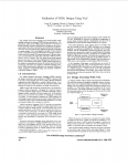
Abstract
VAL (VHDL Annotation Language) provides a small number of new language constructs to
annotate VHDL hardware descriptions. VAL annotations, added to the VHDL entity declaration
in the form of formal comments, express intended behavior common to all architectural bodies of
the entity. Annotations are expressed as parallel processes that accept streams of input signals and
generate constraints on output streams. VAL views signals as streams of values ordered by time.
Generalized timing expressions allow the designer to refer to relative points on a stream. No concept
of preemptive delayed assignment or inertial delay are needed when referring to different relative
points in time on a stream. The VAL abstract state model permits abstract data types to be used
in specifying history dependent device behavior. Annotations placed inside a VHDL architecture
define detailed correspondences between the behavior specification and architecture. The result
is a simple but expressive language extension of VHDL with possible applications to automatic
checking of VHDL simulations, hierarchical design, and automatic verification of hardware designs
in VHDL.
Key Words and Phrases:
simulation, real-time systems
VHDL, hardware description languages, annotation languages,
Copyright @ 1988
bY
Larry M. Augustin, Benoit A. Gennart, Youm Huh,
David C. Luckham, Alec G. Stanculescu
ii
Contents
1 Introduction
1
2 Design Checking With VAL
5
3
Language Basics
3.1 Entity Annotations . . . . . . . . . . . . . . . . . . . . . . . . . . . . . . . . . . . . .
3.1.1 Assertions . . . . . . . . . . . . . . . . . . . . . . . . . . . . . . . . . . . . . .
3.1.2 Entity State . . . . . . . . . . .
3.1.3 Annotation of Timing Behavior
3.1.4 Assumptions . . . . . . . . . .
3.1.5 Other Constructs . . . . . . . .
3.2 Body and Mapping Annotations . . .
3.3 Configuration Annotations . . . . . . .
.
.
.
.
.
.
.
.
.
.
.
.
.
.
.
.
.
.
.
.
.
.
.
.
.
.
.
.
.
.
.
.
.
.
.
.
.
.
.
.
.
.
.
.
.
.
.
.
.
.
.
.
.
.
.
.
.
.
.
.
.
.
.
.
.
.
.
.
.
.
.
.
.
.
.
.
.
.
.
.
.
.
.
.
.
.
.
.
.
.
.
.
.
.
.
.
.
.
.
.
.
.
.
.
.
.
.
.
.
.
.
.
.
.
.
.
.
.
.
.
.
.
.
.
.
.
.
.
.
.
.
.
.
.
.
.
.
.
.
.
.
.
.
.
.
.
.
.
.
.
.
.
.
.
.
.
7
7
8
9
10
13
13
13
14
17
4 VAL Transformer
4.1 Generation of Translation Skeleton . . . . . . .
4.2 Target Independent Transformations . . . . . .
4.2.1 Elimination of Derived Syntax . . . . .
4.2.2 Isolation of Base Statements . . . . . .
4.2.3 Flattening of Nested Guards . . . . . .
4.2.4 Resealing of Timed Expressions . . . . .
4.3 Code Generation . . . . . . . . . . . . . . . . .
4.3.1 Translation of timed expressions . . . .
4.3.2 Translation of time qualified expressions
4.3.3 Translation of drive processes . . . . . .
4.3.4 Translation of assertion processes . . . .
.
.
.
.
.
.
.
.
.
.
.
.
.
.
.
.
.
.
.
.
.
.
.
.
.
.
.
.
.
.
.
.
.
.
.
.
.
.
.
.
.
.
.
.
.
.
.
.
.
.
.
.
.
.
.
.
.
.
.
.
.
.
.
.
.
.
.
.
.
.
.
.
.
.
.
.
.
.
.
.
.
.
.
.
.
.
.
.
.
.
.
.
.
.
.
.
.
.
.
.
.
.
.
.
.
.
.
.
.
.
.
.
.
.
.
.
.
.
.
.
.
.
.
.
.
.
.
.
.
.
.
.
.
.
.
.
.
.
.
.
.
.
.
.
.
.
.
.
.
.
.
.
.
.
.
.
.
.
.
.
.
.
.
.
.
.
.
.
.
.
.
.
.
.
.
.
.
.
.
.
.
.
.
.
.
.
.
.
.
.
.
.
.
.
.
.
.
.
.
.
.
.
.
.
.
.
.
.
.
.
.
.
.
.
.
.
.
.
.
.
.
.
.
.
.
.
.
.
.
.
.
18
19
19
21
21
21
23
24
24
24
25
31
5 Experience, Status, and Future Work
...
111
List of Figures
2.1 Typical Model of Design Checking . . . . . . . . . . . . . . . . . . . . . . . . . . . .
2.2 VAL Model of Design Checking . . . . . . . . . . . . . . . . . . . . . . . . . . . . . .
5
6
3.1
3.2
3.3
3.4
3.5
Annotated VHDL AND Gate Entity Declaration
Annotated D Latch Entity Declaration . . . . . .
Annotated D Flip-Flop Entity Declaration . . . .
Two-bit Counter Entity Declaration . . . . . . .
Two-bit Counter Architecture . . . . . . . . . . .
.
.
.
.
.
.
.
.
.
.
.
.
.
.
.
.
.
.
.
.
.
.
.
.
.
.
.
.
.
.
.
.
.
.
.
.
.
.
.
.
.
.
.
.
.
.
.
.
.
.
.
.
.
.
.
.
.
.
.
.
.
.
.
.
.
.
.
.
.
.
.
.
.
.
.
.
.
.
.
.
.
.
.
.
.
.
.
.
.
.
.
.
.
.
.
.
.
.
.
.
8
10
12
14
16
4.1
4.2
4.3
4.4
4.5
4.6
Relationship Between Design Units . . . .
Translation of Time Qualified Expression
Example of State Maintenance Process . .
Translation of Finally assertion . . . . . .
Translation of Sometime assertion . . . .
Translation of Eventually assertion . . . .
.
.
.
.
.
.
.
.
.
.
.
.
.
.
.
.
.
.
.
.
.
.
.
.
.
.
.
.
.
.
.
.
.
.
.
.
.
.
.
.
.
.
.
.
.
.
.
.
.
.
.
.
.
.
.
.
.
.
.
.
.
.
.
.
.
.
.
.
.
.
.
.
.
.
.
.
.
.
.
.
.
.
.
.
.
.
.
.
.
.
.
.
.
.
.
.
.
.
.
.
.
.
.
.
.
.
.
.
.
.
.
.
.
.
.
.
.
.
.
.
19
25
26
27
28
29
iv
.
.
.
.
.
.
.
.
.
.
.
.
.
.
.
.
.
.
.
.
.
.
.
.
Chapter 1
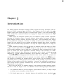
Introduction
The VHSIC Hardware Description Language (VHDL) supports the design, description, and simulation of VHSIC components [17]. It provides a base language that can be used to describe
hardware ranging from simple logic gates to complex digital systems. As an IEEE standard [20],
VHDL will provide an important common base language for design tool development and design
documentation.
VHSIC designs will incorporate anywhere from a few hundred to perhaps a million components.
Managing this complexity requires a powerful hardware design support environment including a
library manager, profiler, simulator, and other design tools. Such environments must address
the key problem of verifying the correctness of a design. If current practice continues, the VHDL
designer will verify designs by using a simulator and manually comparing huge volumes of simulator
output with an informal design specification. For large and complex designs, this is simply not
practical.
VHDL Annotation Language (VAL) [2,3] p rovides an annotation facility that allows the VHDL
designer to make simple kinds of annotations during the design process. VAL annotations have
several possible applications, each of which may be supported by future environment tools. In this
paper, we describe VAL and its application to automatic checking of the correctness of a VHDL
design during simulation. Other applications of annotations, such as formal verification [4,7,5,9],
debugging [14,15,8], and simulation optimization, will be discussed in later papers.
In general, annotation languages permit information about various aspects of a program not
normally part of the program itself to be expressed in a machine readable form [la]. They provide facilities for explaining the intended behavior of the program. They are intended to reduce
programming errors by making programs more readable and by providing a great deal of error
checking at both compile and run time. Readability is improved by enabling the programmer to
express design decisions explicitly. Annotations may also serve as specification and thus precede
implementation of the program.
These ideas still hold for an annotation language in the hardware description language domain,
With this in mind, the design of VAL was undertaken with the following principle considerations:
1. VAL annotations should be powerful enough to express hardware behavior, yet simple enough
to facilitate correct description of that behavior.
2. VAL should appear more as a functional language with parallelism than an algorithmic pro-
gramming language.
3. VAL should be applied to simulation time checking of VHDL, and should not affect the
simulation result.
4. VAL annotations should be general enough to permit the use of formal abstract specifications
during the design phase.
5. The designer should be free to annotate and specify as much or as little as desired.
The VHDL assertion facility allows the designer to specify conditions that are expected to be
true during the course of simulation. VAL achieves its design goals by building on the base provided
by VHDL a set of powerful but simple constructs geared specifically to the annotation of hardware
behavior.
VAL provides five main facilities extending VHDL. VAL provides new constructs for expressing:
1. time dependent behavior
2. abstract data types as models of entity state
3. concurrent processes with subprocesses for expressing behavior
4. temporal assertions
5. detailed mappings between behaviors and architectures
Timing constructs are based on a concept of relative time, which in turn is based on representing
behaviors as streams of values. A stream oriented view of hardware behavior allows the designer
to enter a VAL specification directly from a typical timing description of an entity. New high level
timing constructs, based on relative time, allow simple description of complex timing. Relative
time allows the designer to select any point in the data stream as a reference.
Because many hardware description languages fail to distinguish design constructs from programming constructs they confuse design with programming. VAL permits the designer to model
the state of entities by abstract data types, thus hiding programming details from behavioral specifications. VAL clearly separates programming from design by treating programming as a support
utility and restricting support programming functions to a library environment of packages. VAL
is based on the view that hardware behavior is best expressed by parallel processes with dependent
subprocesses. No sequential programming constructs are present in VAL.
Annotations can only monitor the VHDL simulation and report errors. VAL annotations cannot
modify VHDL objects such as ports. Thus there is no possibility of introducing an error into a
VHDL simulation through a VAL annotation.
VAL and VAL-based tools are intended as extensions of VHDL and VHDL environments. Annotations are included in the VHDL text as formal comments. This allows the annotated description
to be processed simply as a VHDL description without modification to the VHDL analyzer. If
desired, a preprocessor, the VAL Transformer, translates VAL annotations into VHDL source code,
resulting in a self-checking VHDL description. This self-checking VHDL description is then processed by the VHDL tools. Thus a VHDL design including VAL annotations can be compiled and
executed by standard VHDL tools together with the addition of the VAL Transformer.
2
In using VAL there is no assumption that that specification must be complete. The designer is
free to specify only those portions of the behavior that are relevant.
In the remainder of this paper, we will first give an overview of design checking using VAL.
Then we will describe VAL in more detail, showing how VAL annotations are used to generate
constraints on a VHDL simulation. A brief overview of the VAL Transformer demonstrates the
feasibility of our design. We conclude with some observat.ions made from our experience with VAL
to date, and areas for future work.
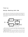
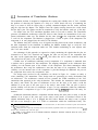
Chapter 2
Design Checking With VAL
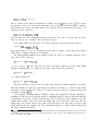
A designer usually verifies a design using some form of simulation. This task often requires the
designer to manually compare the simulation result with an informal design specification. Occasionally, the designer also has a high level behavioral description (written in, for example, C or
Ada) whose output can be compared to the output of the simulator. The design is simulated using
a set of test vectors, the behavioral model is run on the same test vectors, and the results are
compared (Figure 2.1).
Simulation
- Out-put
. Behavioral
Simulation
Test
InIjut
Compare
I
Simulation
b- Out’put
. Structural
S imul at ion
Figure 2.1: Typical Model of Design Checking
While this process of verification is adequate for simple designs, as designs become more complex
it becomes less satisfactory. It is limited in the extent to which it allows the designer to debug a
new design because it assumes a “black box” view of the design unit (or entity), in which the entity
is accessible only through its ports.
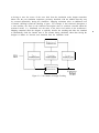
VAL’s model of design checking is based on generating constraints on the entity’s input, internal
state, and output (Figure 2.2). Input constraints allow the simulator to check if an entity is being
used correctly. For example, if the setup or hold time on a signal is not met, the entity can report an
input constraint violation. This helps the designer to spot the source of timing errors as opposed
5
to having to trace the source of the error back from the simulation result. Output constraints
behave like the post simulation comparison previously described, with the addition that they may
be executed dynamically, during the simulation. Mapping constraints allow an additional level
of internal checking beyond the checking of ports. For example, if the behavioral description is
a state machine, the states in the behavioral description must be somehow encoded within the
structural model. (i.e., distributed over the states of the lower level entities in the architecture.)
Mapping constraints allow the designer to explicitly describe the encoding and allow the simulator
to automatically check the internal state of the structure during simulation, rather than forcing the
designer to deduce an incorrect state transition from the simulation result.
Test
In$ut
4 Structural
Simulation
I
Figure 2.2: VAL Model of Design Checking
Simulation
Output
Chapter 3
Language Basics
VAL annotations may appear in all three VHDL design units; entities, architectures, and configurations. Annotations in the entity declaration (entity annotations) express intended behavior
common to all architectures of the entity. They define an abstract model of the entity’s internal
state and use it, in conjunction with the inputs to the entity, to define constraints on values carried
by the output ports. In VHDL, ports of mode out cannot be read within the entity and therefore
assertions cannot normally be made about them. Unlike VHDL, VAL entity annotations have
visibility over the contribution of the entity to each of its out ports. This allows the designer to
define the entity’s contribution to the output port. Constraints may also be defined on input ports.
Static constraints on generic parameters are also declared as part of the entity annotations.
Annotations within the VHDL architecture (body annotations) can be used to constrain the
values of internal signals and ports of components. In addition, VAL annot ations within the
architecture have visibility over the abstract state of the entity (defined by the entity annotations)
as well as the internal states of each component instantiated in the architecture. Annotations in an
architecture relating to state are known as mapping annotations. In effect, mapping annotations
describe the way in which the abstract state introduced in the entity annotations is mapped into
the states of the architecture’s components.
Annotations appearing in a configuration (configuration annotations) allow the user to configure
the VAL portion of the simulation. For example, the user may want to select only some of the
entities in a large simulation for automatic checking. Also, the state model map, similar to a VHDL
port or generic map, can be used to map an assumed state model for a component in an architecture
into the actual state model of the actual component. This allows a designer to assume an abstract
state model for a component that may not yet be available while designing an architecture and
later provide a type conversion function to translate the assumed state model of the component to
the state model of the actual component.
3.1 Entity Annotations
VAL entity annotations may appear in the declarative part and the statement part of the VHDL
entity declaration. Assertions appearing in the declarative part are known as assumptions. Assumptions typically express constraints on generic parameters of the entity and may be checked
statically at compile time.
7
Interface annotations appearing in the entity statement part consist of a list of parallel processes
that execute continuously. Unlike typical programming languages which execute a process once
when it activates, a VAL process executes continuously while active. In many ways this is similar
to actual hardware behavior. For example, an AND gate does not behave by watching its inputs for
a change and recomputing a new output when a change occurs. Instead, it continuously performs the
AND operation. More formally, continuously means that the operation is performed often enough
that performing it any more frequently would not produce any observable change in behavior.
The following sections summarize the most important entity annotation language constructs in
VAL and then show how the VAL concept of relative time, in conjunction with VAL processes,
models hardware behavior.
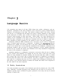
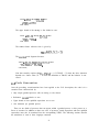
3.1.1 Assertions
An assertion process generates constraints on the simulation. Consider the VHDL entity declaration
for a two input AND gate shown in Figure 3.1. The identifiers input-a and input-b are input ports
and result is the output port. Assertions in the form of VAL processes are added to define the
behavior of this circuit. The behavior of the AND gate is specified by a single assert process that
makes an assertion about the value carried on the output port. The VAL annotations describing
the entity’s intended behavior appear following the VHDL keyword begin. The assert process
continuously checks a constraint (in this case (input-a and input-b) = result). It is similar to
the assert statement in VHDL, but applies to a wider class of elements, such as output ports. If
the constraint ever evaluates to false, the assert process performs the requested action. The else
keyword emphasizes that the severity and report clauses are executed when the boolean expression
is false. The else keyword is optional.
The default severity level of VAL assertions is WARNING.
-- Annotated VHDL two input AND gate
entity TwoInputAND
p o r t (input-a,
result
is
input-b : i n bit;
: out bit);
begin
-- VAL Annotations defining the AND gate’s behavior
--I assert ((input-a and input-b)
--l
severity FAILURE
-- l
report
end
TwoInputAND;
= result) else
"Error in TwoInputAND" ;
Figure 3.1: Annotated VHDL AND Gate Entity Declaration
VAL provides a family of assertion processes for generating constraints. The assert process is
the strictest of these, requiring the constraint to be satisfied at every simulation cycle (i.e. at every
delta). Perfectly correct behaviors will often violate this constraint because a zero delay signal
8
assignment in VHDL occurs after a delay of delta, limiting the usefulness of the VHDL assert
statement for checking this kind of behavior. Other VAL assertion processes operate by generating
constraints only at certain points during the simulation. For example, the finally assertion process
allows the user to specify a constraint that must hold only at the last delta in a simulation time
point. The constraint generated by the annotation in Figure 3.1 will report an error for a single delta
whenever a change in input-a or input-b causes a change in result because the VHDL simulation of
any architecture for this entity does not effect the change until the next delta. Replacing assert by
finally checks only after the assignment has been completed, reflecting more closely the intentions
of the designer.
Unlike VHDL, VAL provides the capability to hierarchically nest assertions using a guarded
process. The keyword when identifies a guarded process that consists of two lists of processes,
corresponding to a then part and an else part, and a boolean guard expression. (See Figure 3.2.)
The else part is optional. The guarded process continuously evaluates a boolean expression, and,
if the expression is true, the processes following the then clause are activated, otherwise those
following the else clause are activated. Note that the boolean expression is evaluated continuously
and any change in its value results immediately in the activation of one branch of the guarded
process and the deactivation of the other branch. Each guard can be viewed as a node in a binary
tree, the two branches being its then and else parts. A process at any level in the tree is active if
and only if all of the guards leading to that point in the tree are active.
3.1.2 Entity State
Because an entity’s future behavior may depend on its past behavior, VAL provides the entity state
as a means of specifying history dependent behavior. An entity’s state model consists of a single
type declaration of any type allowed in VHDL. For example, record types can model devices with
complex states. VAL requires the designer to model the entity state as a single abstract object. It
can be declared as an abstract data type in a VHDL package, along with the functions necessary
to manipulate it, and imported into the VAL description. This allows the designer to import a
generic package describing a Stack, Queue, Petri Net, or whatever abstract object most accurately
expresses the entity’s behavior.
For example, a D latch requires memory to model it. Since the D latch’s memory consists of a
single bit of information, its VAL state model can be declared as:
-- 1 state model
is bit := '0' ;
The keywords state model is indicate that the following type definition (in this example bit)
defines the type of the entity’s state. An initial value for the state (in this example JO’) must be
given. In the behavioral description, the keyword state refers to the state model. The VAL drive
operator -> provides a means for affecting a change in state. It defines a process that, while active,
continuously assigns the value of an expression to an object. Whenever the value of the expression
changes, the value of the object also changes. Drive can only be applied to a component of the
state. When the state of a device is not driven, it retains its last value.
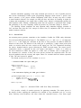
Using the entity state facility and guarded process, the VAL specification of a (flow through) D
latch can be written as described in Figure 3.2. Whenever the clock input is ‘I’, the internal state
of the D latch follows the value on the data input. When the clock goes to zero, the state maintains
9
--
D Latch entity specification
entity Dlatch
port (Clk
is
: in bit;
D
: in bit;
: out bit;
Q
Qb= : out bit);
--I state model is
-- Clock input
-- Data input
-- output
bit := ‘0’ ; -- One bit of memory
begin
--I when (Clk = '1')
-- l
then D -> state;
- - l end when;
-- Level triggered
-- The output always depends on the state
-- 1 assert (state = Q) ;
- - I assert (not state = Qbar);
end
Dlatch;
Figure 3.2: Annotated D Latch Entity Declaration
its last driven value. The value of the outputs always depends on the value of the internal state.
The two assertion processes constrain the value carried by the output ports of any architecture of
the D latch to agree with the value of the state model (and its complement) in the VAL entity
specification.
3.1.3 Annotation of Timing Behavior
A signal in VAL is a sequence or stream of values ordered by time. In general, a hardware entity
describes a mapping between a set of input streams and a set of output streams. All references to
time in VAL describe a relative relationship between streams. Expressions in VAL refer to relative
points along streams. The relative time zero refers the current time. The relative time -t refers to
a point in time that occurs t units before (or in the past) relative to the current time. Similarly,
the relative time t refers to a point in time that occurs t units after (or in the future) relative to
the current, time.
Timed expressions in VAL are simple functions of time that allow the designer to describe
relative timing relationships. The timing operator C 1 can be applied to any object or expression
to refer to its value at any relative point in time. Thus signal-a[-51 refers to the value of signal-a
five time units ago, and signal-a[51 refers to the value of a five units in the future. The expression
signal-a refers to the current value of signal-a and is equivalent to signal-aC0I.
Assertion or drive processes define relative relationships between streams described with timed
expressions. Consider the following process:
10
signal-a[-31 -> s i g n a l - b ;
This is similar to the delayed assignment of VHDL (signal-b <= signal-a after 3;)l except that
the semantics of the VAL process are anticipatory [ll]. In VAL this process describes a relationship between the stream associated with signal-a and the stream associated with signal-b. An
equivalent, process would be:
signal-aC-II
-> signal-bC21
;
This describes the same relationship between the streams; the value on signal-b has the same
shape as signal-b, but is shifted 3 time units into the past.
VAL cannot change the past value of an object. Therefore, non-causal processes such as,
signal-a C51 -> signal-b[-l]
;
(the present value of signal-b is determined by the value of signal-a 6 time units in the future)
which have no physical meaning are not allowed.
The timing qualifier during can be applied to check the value of a boolean expression over a
time interval. The expression
( signal-a = I > during C-3,21
is true
if signal-a = 1 from 3 units ago to 2 units in the future; otherwise it is false. Since timing
qualifiers commonly refer to a range over the most recent interval, the expression
( signal-a = 1) during 5
is a shorter notation for
( signal-a = I) during C-5,01
Note that references to future time can make sense because all timed expressions are relative.
Thus the designer can pick any point along an arbitrary waveform as a reference point when
describing a system’s behavior. There is no need to resort to inertial or transport delays and
preemptive semantics [ 111.
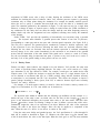
As an example of timing behavior, consider a falling edge triggered D flip-flop. Informally, a
description of this device will typically include a propagation delay as well as setup and hold time
requirements on the data. Assume that the state of the D flip-flop is only changed if the data
remains stable during a time SETUP before the falling edge of the clock and a time HOLD after the
falling edge. Also, assume that the new value of the data takes DELAY time units to appear on the
output after the state has changed. The VAL specification (Figure 3.3) follows almost, exactly from
the above informal description.
IHere, and in the following discussion, the particular unit of time has been neglected since the units are irrelevant
to the current discussion and serve only to clutter the examples. VAL requires (as does VHDL) that all references to
time be of physical type TIME.
11
-- DFlipFlop entity declaration
entity
DFlipFlop is
generic (SETUP, HOLD, DELAY : TIME);
port (Clk : in bit;
-- Clock input
D
: in bit;
-- Data input
: out bit;
-- output
Q
Qb= : out bit);
-- Assertions about generics
--I assume (DELAY >= HOLD)
-- l
report "Error in generic
-- I state model is
constant" ;
bit : = ‘0’ ; -- A single bit of memory
-- State maintenance
--I when Clk'Changed('0') then
--I
when (D'Stable during C-SETUP, HOLD])
-- l
then D -> ~~~~~CDELAY] ;
-- I
end when;
- - l end when;
-- Check outputs
-- I assert ((state = Q) and (not state = Qbar))
-- l
report "Simulator error - D latch" ;
end
DFlipFlop;
Figure 3.3: Annotated D Flip-Flop Entity Declaration
The reference point for the specification in Figure 3.3 is the point at which the clock changes to
The attribute ~'Changed(expression) is TRUE if the value on signal S has changed to the value
of the expression at the current time instant. When ClkJChanged('OJ) becomes true, the guarded
process checking the setup and hold time of the data becomes active. Note that the expression
involving during[-SETUP,HOLD] checks the interval SETUP time units in the past and HOLD time units
in the future. If the data remains stable over this interval, the internal state of the D flip-flop
is modified after a time DELAY. The assertion processes constrain the ports of the VHDL body to
match the state bit, and its negation, at all times.
The constraint DELAY >= HOLD is worth exploring further. Consider any time point t at which
Clk'Changed( '0') is true. The inner nested process is activated. Taking some liberties with the VAL
notation, the signal D is then checked over the interval [t - SETUP, t + HOLD]. If it is stable over the
entire interval (D ) Stable during [t - SETUP,~ + HOLD]) then the drive process (D -> S~~~~[DELAY])
is activated and the value of the signal State at the time point t + DELAY is assigned the value of
‘0’.
12
D. The is description of the D flip-flop’s behavior is (conceptually) executed for every time point t
in the simulation. The assignment to state cannot happen if the time point t + DELAY has already
passed; i.e. t + HOLD > t + DELAY.
Conceptually, this implies that the output can never take on a new value before that new value is
latched into the internal state. If DELAY < HOLD were true, then the output could change after DELAY
time units, but the hold constraint might not yet be met, in which case the output value should
never have changed. In other words, if DELAY < HOLD then the behavior is said to be non-causal.
This is more obvious if the VAL description in Figure 3.3 is rewritten such that the reference point
is the point at which the state is assigned a new value. The relevant lines become,
when
D
D'stable during [-SETUP-DELAY,HOLD-DELAY] then
C-DELAY] -> state Co] ;
end when;
If HOLD - DELAY > 0, then the assignment to the new value of state depends on an event that hasn’t
happened yet - the stability of the input during the hold time.
3.1.4 Assumptions
Static constraints assumed by the specification of the entity such as the DELAY >= HOLD condition
in the D flip-flop can be expressed using the assume declaration. The assume declaration specifies
conditions that should be observed by the user of the entity. An architecture of the entity is
designed under the assumption of this condition. The assume declaration has the same form as an
assertion:
assume
<boolean-expression> [else]
[report <expression>]
[severity <expression>] ;
As with assertions, the keyword else and the report and severity expressions are optional. The
default severity level is WARNING. The boolean expression is assumed to be true, else an error message
defined by the report clause is issued and the simulation may continue or be aborted depending
on the severity clause. Assumptions may appear in the declarative part of the entity declaration
and may apply to generic parameters and constants. The condition assumed must be statically
checkable at elaboration time.
3.1.5 Other Constructs
The previous sections introduced the key elements of the VAL language. VAL also contains additional language constructs for iteration across indexed objects, boolean and existential quantifiers,
a macro facility, and other high-level features to aid in the construction of VAL behaviors. The
reader is referred to [lo] for a complete description of the VAL language.
13
3.2 Body and Mapping Annotations
Any of the VAL processes, with the exception of drive, can appear in the entity body. Body annotations specify implementation details and allow more detailed consistency checking between the
entity annotations (the entity’s functional description) and the VHDL architecture (implementation). Body annotations have visibility over all VHDL signals and ports normally visible at the
point at which the annotation appears, the entity’s state model, and the state models of all entities
instantiated as components.
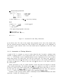
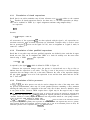
The description of the two-bit modulo four counter in Figures 3.4 and 3.5 together show how
mapping annotations may be used to check the internal state of an entity. The reset signal sets the
state of the counter. Whenever a transition from ‘1’ to ‘0’ on the clock (Clk) occurs, the counter
counts up one. Bit0 represents the least significant bit of the counter and Bit1 the MSB. The VAL
state model is an integer and assert processes generate constraints on the output ports based on
the VAL state.
entity
port
TwoBitCounter is
: in bit;
(Clk
reset
: in bit;
BitO, Bit1
: out bit);
--I state model is integer := 0;
begin
-- l when reset then
-- l
state <- 0;
- - l elsewhen Clk'changed('0') then
-- I
state <- (state + 1) mod 4;
- - I end when;
-
- l select state is
-I
in 0 => finally(Bit0 = ‘0’ and Bit1 = ‘0))
-- l
report "Counter - Output error"
--l
severity warning;
-- l
in I => finally(Bit0 = ‘1’ and Bit1 = )O'>
-- I
report "Counter - Output error"
-- l
severity warning;
--l
in 2 => finally(Bit0 = ‘0’ and Bit1 = '1,)
-- l
report "Counter - Output error"
-- I
severity warning;
-- l
in 3 => finally(Bit0 = ‘1’and Bit1 = '1')
--l
report "Counter - Output error"
-- l
severity warning;
- - l end select ;
end
TwoBitCounter;
Figure 3.4: Two-bit Counter Entity Declaration
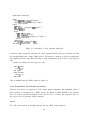
The architecture
SIMPLE
of the counter contains two D-type flip-flops. Each flip-flop is similar
14
to the ones described previously with the exception of a reset signal and the omission of timing
information (to keep the examples short enough to fit in this paper). Each flip-flop has a state
model consisting of a single bit. The states of the flip-flops (DFLI . state and DFL2. state) are related
to the state of the counter (state) by mapping annotations.
3.3 Configuration Annotations
Configuration annotations serve two purposes. First, they provide a local state model mapping
declaration to map the local state model defined in a component declaration to the actual state
model defined by the component’s entity annotations. The state model mapping declaration indicates the function to use in mapping between the state model of the actual entity and the state
model of the component instance. It appears within a configuration specification at the same point
as other binding indications.
Second, they provide configuration information so that VAL generated architectures may be
automatically substituted for original component architectures for checking. The user may not
want to use a VAL annotated entity in place of the original VHDL entity for all components in
a simulation, particularly if the component is a library unit for which no annotated description
exists. The valentity construct allows the user to select the components of an architecture to be
monitored. The VAL Transformer will only generate code to monitor components marked with
valentity. The next section on the VAL Transformer explains how components are monitored. In
Figure 3.5 the valentity configuration annotation indicates that the VAL version of the component
Df lipflop should be used when the simulation is configured.
15
architecture
SIMPLE of TwoBitCounter is
signal Ql,
signal Di,
-- l
Q2, Qlbar, Q2bar : bit;
D2 : bit;
component DFlipFlop
port(Clk, D : in bit;
9, Qbar : out bit;
Reset : in bit);
state model is bit; -- local state model declaration
end component ;
begin
DFLl : DFlipFlop
port map(Clk, Dl, Ql, Qlbar, Reset);
DFL2 : DflipFlop
port map(Clk, D2, 42, Q2bar, Reset);
D2 <= (Ql and Q2bar) or (Qibar and Q2);
Dl <= Qlbar;
Bit0 <= Ql;
Bit1 <= Q2;
mapping annotations relate the state of the counter
to the states of the components
-- l select state is
-- I
0 => finally(DFLZ.state = ‘0’ a n d DFLl.state = ‘0’)
--l
report "Counter state does not match flipflop state"
-- I
severity warning;
-- l
1 => finally(DFL=!.state = ‘0 J and DFLI. state = J I ‘)
--I
report "Counter state does not match flipflop state"
-- l
severity warning;
-- l
2 => finally(DFL2. state = ‘1’ a n d DFLl.state = ‘0’)
-- l
report "Counter state does not match flipflop state"
--I
severity warning;
-- l
3 => finally(DFL2. state = J 1 J and DFLI . state = J 1’)
-- I
report "Counter state does not match flipflop state"
-- l
severity warning;
- - l end select ;
end SIMPLE ;
use
work. all;
configuration A of TwoBitCounter is
-- I valentity;
- - l valarchitecture;
for SIMPLE
for all: DFlipFlop use
entity DFlipFlop(SIMPLE);
-- I valentity;
end for;
end for;
end A;
16
Figure 3.5: Two-bit Counter Architecture
Chapter 4
VAL Transformer
The VAL Transformer runs as a preprocessor on an annotated VHDL description to generate a
self-checking VHDL description. The principles of the translation are described in detail in [16].
Here we describe the translation algorithm in terms of nine simple steps designed to give the reader
an understanding of the principles involved:
1. Elimination of derived syntax.
2. Isolation of base statements.
3. Flattening of nested guards.
4. Resealing of timed expressions.
5. Generation of translation skeleton.
6. Translation of timed expressions.
7. Translation of time qualified expressions.
8. Translation of drive processes.
9. Translation of assertion processes.
The first four steps are independent of the target language (VHDL) and are performed entirely
on the VAL description. They reduce the VAL description to a very simple canonic form, and
must be performed in the outlined order. The final five steps amount to code generation, and are
dependent on VHDL. For performance reasons, the actual translation is not implemented exactly
as in the manner described here.
The following sections describe each of these steps in more detail. In order to give the reader
a better feel for the overall structure of the translation, the generation of the translation skeleton
is described first. The skeleton is independent of the other transformations performed on the
description, so the point at which it is performed is not critical.
17
4.1
Generation of Translation Skeleton
The translation skeleton is designed to implement the scoping and visibility rules of VAL. Consider
the problem of observing the operation of a chip on a circuit board. One way of monitoring the
chip is to remove it from its socket, plug a specially constructed adapter into the socket, and then
plug the chip into the adapter. The adapter senses the signals traveling between the circuit board
and the chip’s pins. The signals can then be monitored to verify the behavior (and use) of the chip.
For simple cases, the VAL translation algorithm works in just such a manner. The Transformer
generates an additional architecture called the Monitor that contains an instantiation of the component (architecture) under test. The Monitor has the same pins 1 as the component, and contains
a socket for the component. The Monitor is plugged into a circuit in place of the component. The
component is in turn plugged into the socket in the Monitor.
The Monitor body has visibility over all signals traveling between the actual architecture and
the other components in the simulation. In addition, the Monitor contains logic to verify the VAL
assertions made about the component under test. This includes maintaining its own separate state
(the VAL state model).
One advantage of this approach (as opposed to simply monitoring the signals that the pins are
connected to) is that VAL assertions can separate the value on out ports of the component from
the value on the signals that those ports drive 2. This allows the user to make assertions about the
value placed on the port by the entity. 3
Consider now an architecture containing several components. If a component is annotated, then
a monitor can be generated for that component. The mapping annotations in the architecture have
visibility over the internal state of the monitor of the component. This allows annotations within
the architecture that “map” the architecture’s state into the states of its components. The needed
visibility over the internal state of the component is provided through an additional out port on
the component that carries the component’s state.
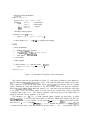
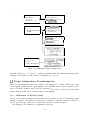
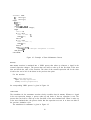
The design units involved in the translation are shown in Figure 4.1. Assume an entity A
exists containing VAL annotations. Three design units are generated; two entity declarations and
an architecture. The architecture (named MONITOR ) contains the VHDL translation of the VAL
annotations that appeared in the entity declaration. This includes the annotations which maintain
the entity’s state model. The ports of architecture MONITOR are the same as for entity A with the
addition of an out port of the same type as the entity’s state model. This out port is used to
provide visibility over the state of components of type A to any annotations within any architecture
that instantiates a component of type A. The generated entity A-OUTSTATE declares the entity for
MONITOR.
Architecture MONITOR contains a
addition of an in port of the same
original architecture body T of A is
into the SOCKET through a port, it
component SOCKET having the same ports as entity A with the
type as the entity’s state model. A translated version of the
plugged into this socket. Because the entity’s state is passed
is visible to annotations within the architectural body. The
1 Almost. It may have an additional output pin, as described later, to allow other assertions to probe the monitored
architecture’s internal state.
2The value placed on a port by an entity does not necessarily equal the value on a signal connected to that port
because bus resolution may come into play.
31n VHDL, a port of mode out is not readable within the architecture. Therefore assertions about out mode ports
cannot be made in VHDL.
18
I
I
architecture S of
TEST-BENCH is
component
TEST-ENTITY : A;
architecture S-EXPANDED
of TEST-BENCH is
cbkponent TEST-ENTITY :
A-OUTSTATE;
...
I
entity A is
- - VAL a n n o t a t i o n s \
c
IPI
II
architecture T
of A is
-- VAL Annotations
entity A-OUTSTATE is
-- entity A plus an
-- additional out port
- - of state type
architecture MONITOR of
A-OUTSTATE is
cbkponent SOCKET :
I
A-INSTATE;
I
1-11
Figure 4.1: Relationship Between Design Units
translated version of T, T-EXPANDED, contains a translation of the VAL annotations appearing in the
architecture into VHDL. Its entity interface is described by A-INSTATE.
4.2 Target Independent Transformations
These four transformations reduce the complete VAL language to a simple canonic form. They
can be applied regardless of the target language of the translator. Most of these operations can be
seen as removing “syntactic sugar” from the description. The result is that the code generations
routines need deal with only a restricted subset of the language.
4.2.1
Elimination of Derived Syntax
Derived syntax refers to language constructs that can be rewritten in terms of syntactically simpler
language constructs. The rules that specify how to eliminate a language construct are known as
rewrite rules since they specify how to rewrite one construct in terms of another.
The following VAL constructs are eliminated by this step:
19
l
- The select process activates one of a set of child processes based on the value of a
selection expression. It can be re-written as a set of when processes. For example,
Select
select <expr>
c2 => sl;
c3 I c4 => s2;
else s3;
cl I
end select ;
becomes,4
when (CI =
<expr>) or (c2 = <expr>) then SI; end when;
when (~3 = <expr>) o r (~4 = <expr>) t h e n ~2; e n d w h e n ;
w h e n ( c l /= <expr>) a n d (c=! /= <expr>) a n d
(c3 /= <expr>) and (~4 /= <expr>) then s3; end when;
A macro is a name for a list of parameterized statements. For every occurrence of
the macro, the statements associated with the macro are copied, and the actual parameters
substituted for the formal parameters. the rewrite rules must be performed recursively on
the result of the expansion.
l
Macro -
l
Generate
l
- The generate statement defines a set of statements parameterized by an index. Generate statements are expanded in-line by making a copy of the code for each index value.
- The syntactically more complex forms of the guarded processes are rewritten
into simpler forms. For example,
Else and elsewhen
when ei then sl;
elsewhen e2 t h e n s3;
else
s4;
end when;
becomes,
when ei then sl; end when;
when not ei and e2 then s3; end when;
when not e1 and not e2 then s4 end when;
4This, and the other rewrite rules, neglect semantic checking. If compile time semantic checks can guarantee no
semantic errors, then the behavior of the rewritten expression is correct. Otherwise the transformation rule can be
extended to include run-time semantic checking.
20
Once the rewrite rules have been performed recursively on the VAL description, only simple
processes (with no else parts), drive processes, and assertion processes remain.
when
4.2.2 Isolation of Base Statements
This step associates a set of guards with a single process. Each guarded process with multiple
processes in it’s then part is rewritten as multiple guarded processes, each with a single process in
its then part. For example,
when ei then SI; ~2; end when;
becomes,
when el then
when el then
Sl;
end when ;
s2; end when;
The processes SI and s2 may be drive, assertion, or guarded processes.
4.2.3 Flattening of Nested Guards
Next, nested guarded statements are flattened. The VAL process
when el then
when e2 then
sl;
end when;
end when;
becomes,
The VAL description now consists of a list of simple (no else clauses) guarded statements, each
guarding a single drive or assertion process.
4.2.4
Resealing of Timed Expressions
Since time in VAL is relative, the reference point of the entire descript on can be shifted in time
such that all references are to the past. This facilitates the translation to VHDL since only the past
value of a signal can be referenced in VHDL. The rules used here for manipulating VAL expressions
are based on the theory described in [l]. Resealing is done in five steps.
1. Generalize defaults -
1.
Default time references are added to every expression. There are two cases:
el during Tl becomes el during[-Ti,O]
2. ei
becomes eiC01
21
2. Set upper bounds
- The upper bound of all time qualified expressions is shifted to zero. The
expression
S during [Tl , T2]
becomes,
S[T21 during [Tl-T2,0]
- Time references are “pushed” through each expression until they are
associated with signals. A timed expression (el CT11 > [T2] is rewritten as (el [Tl + T2] ).
3. Push time references
The interval in time qualified expressions is not affected by pushing time references. For
example,
(ei CT11 during [T2,01)[T21
becomes,
el[Tl + T2] during [T2,0]
This eliminates all expressions of the form (e) CT]. Timed references are now only associated
with signals.
- For each guarded process, the time of the furthest forward
reference of all expressions in that process is computed. This includes expressions in the drive
or assertion process in the then part of the guarded process. This time point will be referred
to as Tmax. For an expression e, MAX(e) = Tmaz is:
4. Compute furthest future reference
- MAX(e) = maximum of all the subexpressions of e
- MAX( e during[Tl,O]) = MAX(e)
- MAX(s CT]) = T
- MAX(Tl,T2,T3,. . . ) = T; if Ti 2 Tj Qj # i
Tmax for a guarded expression is the MAX of all the expressions within the guarded statement
and all of its children. A different Tmaz is computed for each guarded expression.
- Each timed expression, with the exception of time in qualified expressions,
has Tmax subtracted from it. All time references should now be less than or equal to zero.
Qualified expressions are not effected since they refer to an interval, and not to a relative
time point. For example, consider:
5. Rescale time
22
when el
sCT41
CT11 during [T2, T3] then
<- e2[T5];
end when;
The upper bound of the during is first shifted to zero.
when el [Tl-T3] during [T2-T3,0] then
s CT41 <- e2 [T5] ;
end when;
The furthest future reference time is given by:
TMAX= MAX(T4,T5,Tl-T3)
The resealed code fragment becomes:
when el [Tl-TS-TMAX]
during[T2-T3,0] then
s [T4-TMAX] <- e2 [T5-TMAX] ;
end when;
Note that causality requires that T4-TMAX <= 0. If TMAX > T4, then the drive statement
depends on a future value (T5 > T4 from the definition of TMAX) and the behavior is noncausal.
4.3 Code Generation
Once the preceding transformations have been applied to the VAL description, the code is in a
canonical form characterized by:
l
Only simple guarded processes with no nesting or else clauses.
l
References resealed relative to zero.
l
Upper bound of time qualified expressions set to zero.
l
One statement per guarded process.
There are two kinds of processes that can appear within a guarded process: a drive process or a
flavor of assertion. In addition to these two cases of processes, timed expressions and time qualified
expressions must also be translated into the corresponding VHDL. The following sections describe
the translation of each of these language constructs.
23
4.3.1
Translation of timed expressions
Recall that in an earlier translation step all time references were resealed relative to the constant
Tmax. Therefore all timed expressions must be less than zero; i.e. all timed expressions are delays.
This can be modeled in VHDL by a signal assignment statement using transport delay.”
An expression
e CT]
becomes
S <= transport e after T;
All occurrences of the expression eC~1 are then replaced with the signal S. All expressions are
rewritten recursively until all timed expressions are eliminated. Transport delay is used to assure
that no preemption [ll] occurs on the signal. In VAL, once an assignment to a signal is made, in
cannot be “undone.”
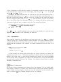
4.3.2
Translation of time qualified expressions
Recall that in an earlier step each time qualified expression was shifted in time such that its upper
bound was zero. This can be translated into VHDL as a check for stability over the most recent
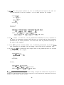
interval using a VHDL process.6 The expression
e during [T , 01
is replaced by the signal GBE2 which is defined in VHDL in Figure 4.2.
Whenever the expression changes value, the process is activated and sets a flag to false to
indicate that the expression is not stable. The flag is reset if the process is not activated (the
expression does not change value) for T time units. Whenever the value of the expression changes,
the new signal GBE2 is set to true if the expression is true and has been stable and true for the
last T time units.
4.3.3
Translation of drive processes
In VAL/VHDL, the drive process can only be used to change the value of the entity state. After
the previous transformations, there may be several guarded processes containing a drive statement
affecting the entity state or a component of the state. Only one of these, however, should be active
at any point in time. Because VHDL requires that a signal may be the target of only a single
‘The predefined VHDL attribute ‘delayed0 cannot be used for this because the argument of ‘delayed0 must
be a globally static expression. (See $7.4 of [20].) Although the argument generated by the translation algorithm is a
“run-time” constant, it is actually computed at elaboration time using functions defined in a VAL package. Therefore
it does not meet the VHDL definition of globally static.
6As with ‘delayedo, the predefined VHDL attribute ‘stable0 cannot be used in the translation because
the argument may not be a globally static expression as defined in VHDL. The argument may not be a globally
static expression because the Transformer introduces function calls as part of the translation process. In effect, the
transformer generates code to implement the ‘stable0 attribute itself.
24
signal GBE2 : BOOLEAN;
block
signal GBEI , GBEI-delay : BOOLEAN;
signal GBEI-stable : BOOLEAN := TRUE;
begin
GBEI <= e ;
GBEI-delay <= transport GBEI after T;
process ( GBEI)
begin
if GBE-1 J event then
GBEI-stable <= FALSE;
GBEI-stable <= transport true after T;
end if;
end process ;
GBE2 <= GBEI-stable and GBEI;
end block ;
Figure 4.2: Translation of Time Qualified Expression
concurrent signal assignment statement, all of the guarded processes that may influence the state
are brought together into a single VHDL process. This process is sensitive to all of the signals that
may influence the state, and checks that only a single assignment to state is active at any point in
time.
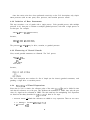
Consider for example the following VAL code:
when Gl then
state <- El;
end when;
when G2 then
state <- E2;
end when ;
This is translated into the VHDL shown in Figure 4.3.
4.3.4 Translation of assertion processes
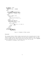
There are four flavors of assertions in VAL: assert, finally, sometime, and eventually. Each of
these assertions is translated into a VHDL process, the details of which depend on the particular
flavor of assertion. Because the default severity level in VAL is WARNING, the translation must set
the severity level of generated VHDL assertions.
Assert
The VAL assert process is translated directly into the VHDL assert statement.
25
VALSTATE: block
Sl : state-type;
s2 : state-type;
begin
Sl <= El;
S2 <= E2;
process ( Sl ,S2 >
variable count
begin
count := 0;
if (Gl) then
: integer;
count := count + I;
state <= Sl;
end if;
if (G2) then
count := count t 1;
state <= S2;
end if;
assert count <= 1
report "VAL Error:
end process ;
end block;
Multiple assignment to state";
Figure 4.3: Example of State Maintenance Process
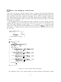
Finally
The finally
assertion is translated into a VHDL process that wakes up whenever a signal in the
asserted expression changes. The process than sets itself to wake up at the first delta of the next
time and checks the value of the assertion. The value of the asserted expression will be the value
it held at the end of all of the deltas in the previous time point.
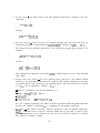
For the assertion
finally <test-expression>
report <message-expression>
severity <severity-expression>;
the corresponding VHDL process is given in Figure 4.4.
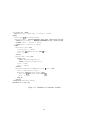
Sometime
The translation for the sometime assertion closely resembles that for finally. Whenever a signal
in the test expression changes, a process wakes up and checks if the test expression is true. The
process then sets itself to wake up on the first delta of the next simulated time. When it wakes up
at the next simulated time, the process checks that the expression was true in at least one delta in
the previous simulation cycle.
The translation for sometime is given in Figure 4.5.
26
VAL-FINALLY1 : block
signal next-time
: BOOLEAN;
signal assert-expr : BOOLEAN;
begin
assert-expr <= <test-expression>;
process ( assert-expr,next-time )
variable first : BOOLEAN := TRUE;
variable oneb : BOOLEAN := TRUE;
begin
if next-time J event then
assert oneb
report <message-expression>
severity <severity-expression>;
first := TRUE;
end if;
if assert-expr'event then
if (assert-expr /= oneb) then
oneb := assert-expr;
first then
next-time <= not next-time after ifs;
first := FALSE;
if
end if;
end if;
end if;
end process ;
end block VAL-FINALLYl;
Figure 4.4: Translation of Finally assertion
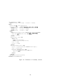
Eventually
The eventually assertion is similar to finally, except that once the test expression goes true it must
remain true during all deltas in the remainder of the time point. the translation is thus very similar
to that for finally, with the addition that the process must check that the test expression ncvcr
makes the transition from false to true and back to false at the same time point.
The translation for eventually is given in Figure 4.6.
27
VAL-SOMETIME : block
signal next-time, assert-expr : boolean := FALSE;
begin
assert-expr <= <test-expression>;
sometimes-label : process ( assert-expr,next-time'transaction
variable initial-cycle : boolean := TRUE;
variable oneb : boolean := FALSE;
variable first : boolean := TRUE;
begin
if initial-cycle then
initial-cycle := FALSE;
next-time <= not next-time after 1 fs;
first := FALSE;
end if;
if next-time) event then
assert oneb
report <message-expression>
severity <severity-expression>;
first := TRUE;
oneb := FALSE;
end if;
if (assert-expr'event or not next-time J event) then
oneb := oneb or assert-expr;
if (first and not assert-expr) then
next-time <= not next-time after ifs;
first := false;
end if;
end if;
end process sometimes-label;
end block VAL-SOMETIME;
Figure 4.5: Translation of Sometime assertion
28
>
VAL-EVENTUALLY : block
signal next-time, assert-expr : boolean := FALSE;
begin
assert-expr <= <test-expression>;
eventually-label : process ( assert-expr,next-time >
variable glitch : boolean := FALSE;
variable oneb
: boolean := FALSE;
variable first
: boolean := TRUE;
begin
if (not
assert-expr'event and not next-time'event) then
next-time <= not next-time after ifs;
first := FALSE;
end if;
if next-time' event then
assert oneb
report <test-message>
severity <severity-expression>;
first := TRUE;
glitch := FALSE;
end if;
if (assert-expr'event) then
glitch := glitch or (oneb and not
assert-expr);
oneb := assert-expr;
if (first and not oneb) then
next-time <= not next-time after Ifs;
first := FALSE;
end if;
end if;
end process eventually-label;
end block VAL-EVENTUALLY;
Figure 4.6: Translation of Eventually assertion
29
Chapter 5
Experience, Status, and Future Work
The VAL Transformer is currently under development. A prototype transformer for a subset of
VAL is currently running with VHDL 7.2. We are currently implementing a VHDL 1076 version of
the Transformer. Very preliminary experiments show that annotations in general may slow down
the simulation by 20% to 70%, depending of the extent of their use. VAL provides a mechanism
(the configuration annotations) for selecting the components that are monitored. This allows the
user to select the level of checking necessary for a given application.
VAL has been used in the design and debugging of several benchmarks of moderate size. These
include the traffic light controller specified in [13] and described in VHDL in [18], the two-bit
counter from which earlier examples have been taken, the ALU in [19], and a simple 16-bit CPU.
In all cases the VAL annotation has provided a clean and simple specification of the intended
behavior. Perhaps more importantly, the design checking provided by VAL significantly increased
our confidence in the correctness of the design. In one instance (the two-bit counter described
earlier), an outright design bug missed by the designer in reviewing the VHDL simulation output
was flagged and quickly located when the same simulation was automatically checked using VAL.
Mapping annotations were particularly useful in isolating the cause of the error. The reason for
this is that they allow the subcomponent related to an error to be immediately identified, since
an error is detected as soon as an assertion is violated, not just at the outputs of a component.
Currently we are focusing on gaining more experience with annotating larger benchmarks.
Language extensions such as additional abstraction mechanisms may be necessary for large and
complex entities. Additional kinds of annotations, such as package, type and subtype constraints
akin to those in [12] might also be useful. While the current mapping annotations have so far proved
adequate, their coarse granularity doesn’t provide the detailed level of constraint checking that
might be needed. As an aid in debugging, a means of enabling and disabling more detailed assertions
would be useful. Finally, VAL’s semantics were kept simple to allow the potential application of
formal verification methods [4,7,6,9,5]. Formal verification would provide a degree of verification
beyond or perhaps in addition to the current model of simulation time constraint checking.
We view VAL as a trend in hardware design languages, and not as a finished project. The
next development will probably be constructs for expressing design hierarchy. These are clearly
required, even to develop our current VAL checker into a design debugger for use with VHDL
simulators. Hierarchy constructs are quite clearly needed to pursue more ambitious applications of
design languages such as mathematical verification of designs and (semi-automatic or interactive)
31
synthesis.
32
Bibliography
PI
L. M. Augustin. An Algebra of Waveforms. Technical Report CSL-TR-88-??, Computer
Systems Laboratory, Stanford University, July 1988. (under preparation).
PI
L. M. Augustin, B. A. Gennart, Y. Huh, D. C. Luckham, and A. G. Stanculescu. VAL:
An annotation language for VHDL. In International Conference on Computer-Aided Design
(ICCAD ‘$7) Digest of Technical Papers, pages 418-421, Santa Clara, CA, November 1987.
PI
L. M. Augustin, B. A. Gennart, Y. Huh, D. C. Luckham, and A. G. Stanculescu. Verification of
VHDL designs using VAL. In Proceedings of the 25th Design Automation Conference (DAC),
pages 48-53, Anaheim, CA, June 1988.
PI
0. J. Dahl. Can Program Proving be Made Practical?
Informatics, University of Oslo, May 1978.
PI
J. A. Darringer. The application of program verification techniques to hardware verification.
In Proceedings of the 16th Design Automation Conference (DAC), pages 375-381, 1979.
PI
M. J. C. Gordon. Hardware Verification by Mechanized Formal Proof. CSL Colloquium Lecture
Notes, The Aerospace Corporation, November 1987.
PI
M. J. C. Gordon. How to Specify and Verify Hardware Using Higher Order Logic. Lecture
Notes, University of Texas at Austin, Autumn 1984.
PI
D. Helmbold and D. Luckham. Debugging Ada Tasking Programs. Technical Report CSL-84
262, Computer Systems Laboratory, Stanford University, Stanford, CA, July 1984.
PI
Y. Huh. Formal Specification and Verification of Hierarchical VLSI. PhD thesis, Stanford
University, Department of Electrical Engineering, Stanford, CA, December 1985.
Technical Report 33, Institute of
LC 11 D. C. Luckham, Y. Huh, A. G. Stanculescu, L. M. Augustin, and B. A. Gennart. VAL
Language Reference Manual. Computer Systems Laboratory, Stanford University, Stanford,
CA, 1988.
11.] D. C. Luckham, A. Stanculescu, Y. Huh, and S.Ghosh. The semantics of timing constructs
in hardware description languages. In IEEE International Conference on Computer Design:
VLSI in Computers (ICCD ‘86), pages 10-14, Port Chester, New York, October 1986.
W
D. C. Luckham and F.W. vonHenke. An overview of ANNA, a specification language for Ada.
IEEE Software, 2(2):9-22, March 1985.
33
[13] C. Mead and L. C onway. Introduction to VLSI Systems. Addison-Wesley, 1980.
[14] S. Sankar. Automatic Runtime Consistency Checking and Debugging of Annotated Programs
(An Overview,). Technical Report under preparation, Computer Systems Laboratory, Stanford
University, Stanford, CA, 1988.
A Note on the Detection of an Ada Compiler Bug while Debugging an Anna
Program. Technical Report under preparation, Computer Systems Laboratory, Stanford Uni-
[15] S. Sankar.
versity, Stanford, CA, 1988.
[16] A. G. Stanculescu. VHDL Annotation Language (VAL): Transformation of Annotated Entities.
Technical Report under preparation, Computer Systems Laboratory, Stanford University, 1988.
[17] VHDL Design Analysis and Justification. Intermetrics, July 1984. IR-MD-018-l.
[18] V H D L User’s Manual: Volume III - Benchmarks. Intermetrics, Inc., 4733 Bethesda Ave.,
Bethesda, MD 20814, July 1984. IR-MD-029.
[19] VHDL User’s Manual: Volume I - Tutorial. Intermetrics, Inc., 4733 Bethesda Ave., Bethesda,
MD 20814, August 1985. IR-MD-065-1.
[20] IEEE Standard VHDL Language Reference Manual. IEEE, Inc., 345 East 47th Street, New
York, NY, 10017, March 1987. IEEE Standard 1076-1987.
34