1
Linking a Simulation Model to a Schematic
Component
Summary
Application Note
AP0142 (v1.1) March 19, 2008
This application note provides information on getting a simulation model – obtained
outside of Altium Designer – into a format supported by the software, and then linking
that model to a schematic component. Linking from an external database is also
covered.
Altium Designer provides a powerful mixed-signal circuit simulator, enabling you to thoroughly analyze a circuit – not only
observing its behavior, but also ensuring that it operates within specific design constraints. To simulate a design successfully, all
components in the circuit must be simulation-ready, that is, they must each have a linked simulation model defined for them.
Altium Designer comes with a host of components stored within manufacturer-specific integrated libraries. Many of these
components have linked simulation models, making creation of a simulation-ready circuit quick and efficient – a case of Place 'n
Simulate if you will.
With such a vast pool of components available to designers in the real world, there will often be times where the component(s)
required for use in a circuit will need to be created in libraries added by the user. As well as defining the component's symbol, a
simulation model for that component needs to be acquired and then linked, in order to make that component simulation-ready.
Acquiring the Model
A simulation model can be obtained from many and varied sources. The following is a non-exhaustive list of possible places or
methods to get the model you require for a target device you wish to use in your design:
•
Manufacturer – a popular place to look for a model is on the website for the manufacturer that makes the device you want
to use. Typically, there will be a link to any available model from the page dealing with the specific device. Models are
®
commonly supplied in SPICE or PSpice format.
•
Altium Designer's SPICE Model Wizard – use this wizard to create and automatically link a SPICE3f5 device model to an
existing or new library component. If linking to a new component, that component will be created automatically by the wizard.
The following device model types are supported: Semiconductor Capacitor, Semiconductor Resistor, Current-Controlled
Switch, Voltage-Controlled Switch, JFET, Lossy Transmission Line, Uniform Distributed RC Transmission Line, Diode and
BJT.
•
Third-Party Modeling Tools – various simulation software packages contain features for modeling a device. This typically
takes the form of a model wizard.
•
Dedicated Modeling Companies – you may be able to source the required model from a third-party company which
creates simulation models based on a given specification.
•
By Hand – the required model can be created yourself, from scratch. This will typically require good knowledge of the
language in which the model definition is being written, for example when creating a subcircuit, or a digital device definition
using Digital SimCode™. When creating a simple MDL file for a built-in SPICE3f5 or supported PSpice model, you will need
good knowledge of the parameters available for, and supported by, that device.
For more information on using Altium Designer's Spice Model Wizard to create a simulation model, refer to the application
note SPICE Model Creation from User Data.
For more information on the various predefined models available with Altium Designer, including information on the built-in
analog SPICE3f5 and supported PSpice models, refer to the Simulation Models and Analyses Reference.
For more information on working with digital device models, refer to the application note Creating and Linking a Digital
SimCode Model.
AP0142 (v1.1) March 19, 2008
1
Linking a Simulation Model to a Schematic Component
Readying the Model for the Altium Designer Arena
Once you have the required simulation model, you need to ensure that it is in a form compatible with Altium Designer. To begin
with, it must be in one of the supported model formats:
•
SPICE3f5
•
XSpice
•
PSpice
For a simple model, the definition must be saved with an mdl extension (e.g. MyBJT.mdl). For
a more complex SPICE subcircuit, the definition must be saved with a ckt extension (e.g.
MyOpAmp.ckt).
With Altium Designer's support for
PSpice models, very little will need
to be done to the majority of
models acquired in PSpice format,
other than to paste the required
model into a file with the MDL
extension.
Model Conversion
®
There are many variants of SPICE out in the design world today – SPICE3f5, PSpice ,
®
®
®
HSPICE , NSPICE and Eldo to name but a few. Discussion of these various formats
and the models they support is beyond the scope of this document.
The majority of manufacturers will provide pure SPICE (SPICE3f5) or PSpice formats. If
your model is in a format other than those supported by Altium Designer, or it is a PSpice
model type that is currently not supported, you will need to convert it into the required
format. This is a manual process, requiring the user manuals for both source (e.g.
PSpice) and target (e.g. SPICE3f5) SPICE formats and, preferably, a detailed knowledge
of the two. Compare the syntaxes of the two formats and convert to something
compatible.
Some commercial versions (or variants) of
SPICE have proprietary extensions that limit
the portability of model descriptions
between different vendor SPICE formats.
If a PSpice model type is supported but a
particular parameter is not, that parameter,
in many cases, can be ignored with only
minor impact on the simulation results.
However, the true impact on the results will
depend on which parameter it is and the
nature of the circuit/simulation.
Linking the Model to a Schematic Component
Once you have the required simulation model file, you will need to link it to the schematic component that you wish to place and
use in your design.
To illustrate by example the steps that need to be taken to link a model to a schematic component, we shall use a simple (and
fictitious) diode model – JAS33 – obtained from a manufacturer and pasted into the file JAS33.mdl.
Creating the Schematic Component
The first step (typically) when creating a new simulation-ready device is to create a
schematic library component for that device and define the symbol graphics. This is done
using Altium Designer’s Schematic Library Editor.
Often, you’ll find it easier to copy an
existing component and then modify it as
required, rather than create the
component and related graphics from
scratch.
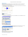
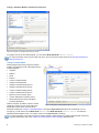
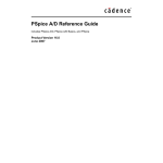
Figure 1 shows the symbol graphics for our simple diode component DIODE JAS33.
Figure 1. Defining the component in the Schematic Library Editor.
For details on creating components in Altium Designer, refer to the Creating Library Components tutorial.
2
AP0142 (v1.1) March 19, 2008
Linking a Simulation Model to a Schematic Component
Adding the Link
Whether you have created a new schematic component, or are using an existing one, it is now time to create a link to the
simulation model file. The first step in this process is to add a simulation model link to the component, carried out in the
Schematic Library Editor in one of the following ways:
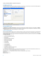
•
In the Models region of the Editor's main design window, click on the drop-down arrow associated with the lower-left button
and choose Simulation from the list of available model types.
Figure 2. Adding models from the main editing window.
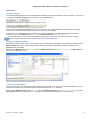
•
In the Models region of the SCH Library panel, click on the associated Add button and choose Simulation as the model
type in the Add New Model dialog that appears.
Figure 3. Adding models from the SCH Library panel.
•
Use the Model Manager dialog (Tools » Model Manager). Simply select the entry for the component, click on the dropdown arrow associated with the Add button, and choose Simulation from the list of available model types.
Figure 4. Adding models using the Model Manager.
AP0142 (v1.1) March 19, 2008
3
Linking a Simulation Model to a Schematic Component
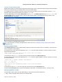
Configuring the Link
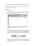
Whichever method you use to add a simulation model link to a component, you will be taken to the Sim Model dialog (Figure 5)
– command central for configuring the link to the required simulation model.
Figure 5. Configuring the model link in the Sim Model dialog.
Specifying Model Type
The Model Kind and Model Sub-Kind fields need to be set according to the particular model type you are linking. The Model
Kind drop-down gives access to a number of model categories containing the range of analog device models built-in to SPICE.
The Model Sub-Kind region lists all model types in a chosen category.
Linking to a SPICE3f5 Model
Many of the built-in SPICE models require no model file. Definition is made by setting the required values for model parameters
at the component-level. The following is a list of the device models that support the use of an associated model file, which can
contain a variety of parameters used to model advanced characteristics of the device. (Entries in the list are in the format Model
Kind\Model Sub-Kind).
•
Current Source\Piecewise Linear
•
General\Capacitor(Semiconductor)
•
General\Diode
•
General\Resistor(Semiconductor)
•
Switch\Current-Controlled
•
Switch\Voltage-Controlled
•
Transistor\BJT
•
Transistor\JFET
•
Transistor\MESFET
•
Transistor\MOSFET
•
Transmission Line\Lossy
•
Transmission Line\Uniform Distributed RC
•
Voltage Source\Piecewise Linear.
If you are linking a SPICE 3f5 model for any of these inherent SPICE devices, simply select the Model Kind and Sub-Kind, as
per the above list. The required Spice Prefix field will be set automatically.
Considering our JAS33 example diode model, the entries in the dialog at this point would be:
Model Kind: General
Model Sub-Kind: Diode
4
AP0142 (v1.1) March 19, 2008
Linking a Simulation Model to a Schematic Component
Spice Prefix: D.
The Netlist Template
The netlist template allows access to the information that is entered into the XSpice netlist for a given component. It is accessed
by clicking on the Netlist Template tab at the bottom of the Sim Model dialog.
Figure 6. Example netlist template entry for a coupled inductor model.
It is read-only for the predefined SPICE3f5 model types. If, however, one of these predefined entries does not allow enough
control over the information placed in the netlist, you can define your own template.
To define your own netlist template, and indeed this is a requirement of certain model types (discussed elsewhere in this
document), simply set the Model Kind to General and the Model Sub-Kind to Generic Editor.
For more information on using the Netlist Template, including syntax rules, refer to the section The Netlist Template –
Explained, which can be found in the Simulation Models and Analyses Reference.
Linking to an XSpice Code Model
When linking an XSpice code model to the component, use of a model file is not applicable. The model itself is defined using the
Netlist Template tab of the Sim Model dialog, with the parameters specified in the template declared and defined on the
Parameters tab of the dialog.
Ensure that the Model Kind is set to General and that the Model Sub-Kind is set to Generic Editor. The Spice Prefix for
this type of model must be set to A.
Figure 7. Parameter declarations for an XSpice model.
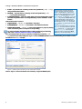
Linking to a Subcircuit Model
If the model you wish to link has been described using the hierarchical sub-circuit syntax (for an operational amplifier or crystal
oscillator for example), the model definition will have been saved to file with a ckt extension.
Ensure that the Model Kind field is set to General and that the Model Sub-Kind is set to Spice Subcircuit. The required
Spice Prefix field will be set automatically to X. Figure 8 shows an example simulation link to a crystal subcircuit.
AP0142 (v1.1) March 19, 2008
5
Linking a Simulation Model to a Schematic Component
Figure 8. Example of a linked SPICE subcircuit model.
For greater control over the netlist template, you can set the Model Sub-Kind to Generic Editor.
For more information on this type of model, refer to the Sub-circuit based models section of the Simulation Models and
Analyses Reference.
Linking to a PSpice Model
Altium Designer offers strong support for PSpice
models. The following is a list of the PSpice device
models supported:
•
Capacitor
•
Resistor
•
Diode
•
Inductor
•
Current-Controlled Switch
•
Voltage-Controlled Switch
•
Voltage-Controlled Voltage Source
•
Voltage-Controlled Current Source
•
Current-Controlled Voltage Source
•
Current-Controlled Current Source
•
Bipolar Junction Transistor (BJT)
•
Junction Field Effect Transistor (JFET)
•
Metal Oxide Semiconductor Field Effect
Transistor (MOSFET)
With the exception of Resistor, Inductor and the
Figure 9. Example of a linked PSpice Inductor model.
voltage and current sources, simply select the
Model Kind and Sub-Kind, as per the list for
SPICE3f5 models (see Linking to a SPICE3f5 Model). The required Spice Prefix field will be set automatically. For the
exceptions, you will need to set the Model Kind to General, the Model Sub-Kind to Generic Editor and enter the
applicable netlist template format. You will also need to set the Spice Prefix accordingly.
For more information on the level of support for PSpice models in Altium Designer, including netlist template entries and
supported parameters, refer to the Support for PSpice Models in Altium Designer application note.
6
AP0142 (v1.1) March 19, 2008
Linking a Simulation Model to a Schematic Component
Linking to a Digital SimCode Model
Digital device models are created using the Digital SimCode language. This is a special descriptive language that allows digital
devices to be simulated using an extended version of the event-driven XSpice.
For a digital device, the schematic component is linked to the SimCode model by using an intermediate model file (*.mdl) –
effectively calling the SimCode description from within its .MODEL line.
In the Sim Model dialog, ensure that the Model Kind is set to General, the Model Sub-Kind is set to Generic Editor and
the Spice Prefix is set to A. You will need to enter the netlist template specific to the digital device being modeled, on the
Netlist Template tab of the dialog.
Figure 10. Example of a linked Digital SimCode model.
For more information on working with digital device models, refer to the Creating and Linking a Digital SimCode Model
application note.
Specifying Model Name
Use the Model Name field in the Sim Model dialog to specify the name of the model to which you are linking. This must be the
name, as it appears in the model file.
For an MDL file, the name must be that appearing in the .MODEL line of the model's definition. Consider a model for a diode
with the following definition:
.MODEL 1N4002 D(IS=2.55E-9 RS=0.042 N=1.75 TT=5.76E-6 CJO=1.85E-11
+ VJ=0.75 M=0.333 BV=100 IBV=1E-5 )
The model name here is 1N4002. This is the name that must be entered into the Model Name field.
For a CKT file, the name must be that appearing in the .SUBCKT line of the model's definition. Consider a model for a fuse with
the following definition:
.SUBCKT FUSE 1 2 PARAMS: CURRENT=1 RESISTANCE=1m
SW1 1 2 3 0 SMOD OFF
BNLV 3 0 V=(abs(v(1,2)))
.MODEL SMOD SW (VT={(CURRENT*RESISTANCE)} RON=1g ROFF={RESISTANCE})
.ENDS FUSE
The model name here is FUSE. This is the name that must be entered into the Model Name field.
Use the optional Description field to enter a brief description of the model – for example its purpose – should you wish.
Specifying Model Location
Use the Model Location region of the Sim Model dialog to control where the model is searched for:
•
Any – searches all valid model locations for a matching model.
AP0142 (v1.1) March 19, 2008
7
Linking a Simulation Model to a Schematic Component
•
In File – only searches for a matching model in the specified file (*.mdl, *.ckt),
along all valid model locations.
•
Full Path – only searches for a matching model in the specified file (*.mdl,
*.ckt) along the specified path.
•
In Integrated Library – draws the model directly from the integrated library used to
place the component instance. The integrated library must be available in a valid
location.
Valid model locations consist of:
•
Project Models – .mdl or .ckt files added to the project
•
Installed Models – .mdl or .ckt files added to the Installed Libraries list
•
Project Search Paths – .mdl or .ckt files made available to a project by defining
one or more search paths in the Options for Project dialog.
For more information about linked models, including referencing and searching,
refer to the Component, Model and Library Concepts article.
When the search is across all valid model
locations, the order of the search is Project
Models – Installed Models – Project Search
Paths. The search ceases as soon as a match
is found – i.e. the Model Name entry in the
.MODEL line of a .mdl file (or the .SUBCKT line
of a .ckt file) matches the Model Name entry
in the Sim Model dialog for that component.
Typically the model file is named the same as
the model itself, e.g. the .MODEL line contains
74LS74 and the .mdl file has been saved with
the name 74LS74.mdl.
This is not a constraint however. For example,
the .MODEL line could contain the model name
74LS74 and then the .mdl file saved with the
name DFlipFlop.mdl. This file would be
yielded as a match, provided that the Model
Name entry in the Sim Model dialog is 74LS74.
Once successfully linked, an entry for where the corresponding model file (*.mdl,
*.ckt) has been found will be displayed. Figure 11 shows the Model Kind tab of the Sim Model dialog with the Model Location
information for our JAS33 example.
Figure 11. Model location information for the JAS33 diode example.
Notice in Figure 11 that the model has been located by using the Full Path option.
8
AP0142 (v1.1) March 19, 2008
Linking a Simulation Model to a Schematic Component
Mapping the Ports
Once the simulation model file has been linked to the schematic component, you need to ensure that the pins of the schematic
component are correctly mapped to the pins of the model. This is carried out on the Port Map tab of the Sim Model dialog.
For the built-in SPICE3f5 and supported PSpice
models, the function of each of the pins in a
model can be found in the general form section
for that model, in the SPICE 3f5 user manual.
For subcircuit models, the manufacturer will
typically insert comments for each pin of the
model, describing that pin's function. If no
commenting is evident, then the pinout of the
model will typically be that of the physical
device itself. Consult the datasheet for the
device in this case.
For Digital SimCode models, the mapping of
the component pins to the INPUTS and
OUTPUTS declared in the SimCode file will
depend on the input and output node list entries
in the netlist template. For more detailed
information, refer to the Creating and Linking a
Digital SimCode Model application note.
Figure 12. Ensuring correct component pin-to-model port mapping.
For each schematic pin, simply use the available drop-down to change the associated Model Pin entry accordingly. If the
device is multi-part, be sure to check the mapping for each part.
Defining Component-Level Parameters
For many model types it is possible to set one or more parameters at the component level.
This is carried out on the Parameters tab of the Sim Model dialog.
For the built-in SPICE3f5, supported
PSpice and subcircuit model kinds, the
available parameters will automatically be
listed. When linking models using the
Generic Editor you will need to add
applicable parameters manually.
For some of the built-in SPICE3f5 models, entering a value for a parameter at the
component level will override a related parameter defined in a linked model file (*.mdl).
For a semiconductor capacitor, for example, specifying a value for the component-level
Width parameter will override any value specified for the DEFW parameter in the associated model file.
If a parameter is specified at the component level for a subcircuit model, that value will override the value defined for it in the
linked subciruit file (*.ckt).
If a parameter is specified at the component level for a digital device, that value will override the value
specified for that parameter in the source SimCode definition.
Figure 13 shows the parameters available for our JAS33 diode device model. If you require any
parameter values to be displayed on the schematic sheet, simply enable the corresponding Component
Parameter option.
Many component-level
parameters will have a
default value assigned to
them which, although not
displayed, will be used if
no specific value is set.
Figure 13. Component-level parameters for the JAS33 diode example.
For more information regarding parameters set at the component level for each of the built-in analog SPICE3f5 models,
predefined XSpice and subcircuit models and TTL and CMOS digital device models, refer to the relevant sections of the
Simulation Models and Analyses Reference.
AP0142 (v1.1) March 19, 2008
9
Linking a Simulation Model to a Schematic Component
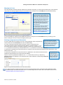
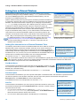
Linking from an External Database
Altium Designer provides the ability to place components directly from a company
database by creating and using a Database Library (*.DBLib). Placement is carried
out from the Libraries panel which, after installing the database library, acts as a
browser into your database (Figure 14).
With this method of linking the component symbol, model and parameter information for
a component is stored as part of the record definition for that component in the external
database. The referenced schematic component (in an underlying component library
(*.SchLib)) is simply an empty shell, with a defined symbol only. There are no linked
models and no defined design parameters. When the component is placed, its
parameter and model information is created on-the-fly, using the corresponding fields in
the matched database record and in accordance with defined mapping.
As part of the Database Library feature, you can add simulation model information to a
component record in the external database. When the component is placed on the
schematic, this information will be used to create the link to the referenced simulation
model – filling-in the required (and corresponding) areas of the Sim Model dialog.
For detailed information on using the Database Library feature, refer to the Using
Components Directly from Your Company Database application note. This
document should ideally be read prior to, or at least in conjunction with, the
remainder of this document.
Figure 14. Component placement (with
sim link) direct from a database library.
Adding Sim Information to an External Database Table
The following sections discuss each of the database fields that can be added to an external
database table in order to define the simulation model link, which will be created upon
component placement. If the field names are named exactly as indicated, the Database
Field-to-Design Parameter mapping will be automatically set on the Field Mappings tab of
the DBLib file. You can, of course, use your own field names in the database table, but you
will then need to manually map these fields to the correct design parameters.
Simulation information must be entered
manually into the external database. Using
the Integrated Library to Database Library
Translator Wizard will not extract the
required simulation information and store it
into the target database.
We shall use our trusty JAS33 diode model to illustrate the linking.
Only one simulation model link can be defined in an external database. Typically there will only ever be a single model linked
to the component. Should you wish to set up multiple simulation model links, the other links will need to be defined and
stored with the component in the source schematic library file.
Sim Model Name
Create this field in the database to specify the name of the model that you wish to use. After
the component is placed, this information will appear in the Model Name field, on the Model
Kind tab of the Sim Model dialog.
In the database record for our example diode, we would enter JAS33 into this field.
When mapping database fields to
design parameters in the DBLib file, the
Sim Model Name field is analogous to
the Footprint Ref, Library Ref, etc,
fields.
Sim Description
Create this field in the database if you wish to provide a description for the linked model. This information is optional and does
not affect the operation of the simulation model link. After the component is placed, this information will appear in the
Description field, on the Model Kind tab of the Sim Model dialog.
In the database record for our example diode, we could enter DIODE.
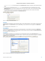
Sim File
Create this field in the database if you wish to specify a particular model file in which to find
the simulation model specified in the Sim Model Name field. There are a number of ways in
which this field can be used:
•
You can enter an absolute path to a model file (e.g. C:\DBLibs\Switching
Diodes\Libraries\JAS33.mdl). The model specified in the Sim Model Name field
will be searched for within this file and used if found.
•
You can enter a relative path (relative to the DBLib file) to a model file (e.g.
10
When mapping database fields to
design parameters in the DBLib file, the
Sim File field is analogous to the
Footprint Path, Library Path, etc,
fields.
Search paths are defined for the DBLib
file from the Symbol & Model Search
Paths tab of the Database Library
Options dialog (Tools » Options).
AP0142 (v1.1) March 19, 2008
Linking a Simulation Model to a Schematic Component
Libraries\JAS33.mdl). The model specified in the Sim Model Name field will be searched for within this file and used if
found.
•
You can enter the model filename only (e.g. JAS33.mdl). Search paths defined as part of the DBLib file will be used to
locate the first model file that matches the specified name, and which contains a match for the model specified in the Sim
Model Name field.
•
You can leave the field blank. Search paths defined as part of the DBLib file will be used to locate the first model file
containing a match for the model specified in the Sim Model Name field.
Figure 15. Providing model location information.
Sim Kind
Create this field in the database to specify the parent category for the model being linked to. This information corresponds to the
Model Kind field, on the Model Kind tab of the Sim Model dialog. The text entered must be as it appears in the Model Kind
field.
For our example diode, we would enter General.
Sim SubKind
Create this field in the database to specify the type of model being linked to. This information corresponds to the Model SubKind field, on the Model Kind tab of the Sim Model dialog. The text entered must be as it appears in the Model Sub-Kind field.
For our example diode, we would enter Diode.
Sim Netlist
Create this field in the database if you are specifying your own netlist template and have set the Sim SubKind field to Generic
Editor. Simply enter the netlist template information. After the component is placed, this information will appear on the Netlist
Template tab of the Sim Model dialog.
Figure 16. Example netlist specification for a linked digital device model (74LS74).
AP0142 (v1.1) March 19, 2008
11
Linking a Simulation Model to a Schematic Component
Sim Spice Prefix
Create this field in the database to specify the SPICE prefix for the model type you are linking to. This information corresponds
to the Spice Prefix field, on the Model Kind tab of the Sim Model dialog.
For our example diode, we would enter D.
For information on the Spice prefix required for a particular model type, refer to the relevant section for that model type in the
Simulation Models and Analyses Reference.
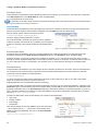
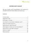
Sim Port Map
Create this field in the database to specify the mapping of pins from the schematic component to the pins of the linked model.
After the component is placed, this information will appear on the Port Map tab of the Sim Model dialog.
Each pin pairing must be entered in the following format:
(SchematicPinNumber:ModelPinNumber),
with each mapped pairing separated by a comma.
For our diode example, schematic pin 1(anode) must be mapped to
model pin 1(anode), and schematic pin 3 (cathode) must be mapped to
model pin 2 (cathode). This would be entered into the database field
as:
(1:1),(3:2)
Figure 17. Specifying component-to-model pin mapping.
Sim Excluded Parts
Create this field in the database if you wish to exclude certain parts of a multi-part component from being simulated. This
information corresponds to the Exclude part from simulation option on the Port Map tab of the Sim Model dialog.
By default, all parts of a multi-part component are included in a simulation, so you only need to specify the parts you wish to
exclude, by number. Separate multiple parts in the exclusion list using commas. For example if a component has four parts and
you do not want parts 2 and 4 to be included in any simulation, then you would enter the following into the database field:
2,4
Sim Parameters
Create this field in the database if you wish to assign values to simulation parameters for the model. These are parameters that
can be defined at the component-level, as opposed to the more advanced parameters that can be included in a model file.
A parameter must be entered in the following format:
ParameterName=Value,
To check on supported component-level parameters (and syntax) for the model type you wish to use, refer to the relevant
section of the Simulation Models and Analyses Reference.
Multiple parameters must be separated by the pipe character (|).
You may remember that a component-level simulation parameter can also be set as a component parameter – appearing in the
Parameters region of the associated Component Properties dialog, with the ability to then be displayed on the schematic sheet.
By default, a parameter entry in the Sim Parameters field will be automatically added as a component parameter. If you do not
want a simulation parameter to be added as a component parameter, simply add an exclamation mark prefix to the parameter
name (e.g. !Initial Voltage=100mV).
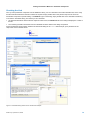
Consider our diode model, which has the following four component-level parameters:
•
Area Factor
•
Starting Condition
•
Initial Voltage
•
Temperature.
Now consider adding values in the database for the Area Factor (say
2) and Temperature (say 22°C). Also, both of these should not be
added as component parameters. The entry in the Sim Parameters
field would be:
!Area Factor=2|!Temperature=22
Figure 18. Specifying values for associated model
parameters (component-level).
12
AP0142 (v1.1) March 19, 2008
Linking a Simulation Model to a Schematic Component
Checking the Link
Once you have placed the component from the Database Library, it is not a bad idea to check the simulation link, and to verify
that the information defined for the link is indeed as required. Simply double-click on the placed component to access its
associated Component Properties dialog. In the Models region of the dialog, simply double-click on the simulation model entry
to access the Sim Model dialog, from where you can check that:
•
Any linked model file has been located as expected. When found, the Model File tab of the dialog will display the content of
the file.
•
The remaining simulation information from the database has been added to the dialog as expected.
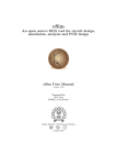
Figure 19 illustrates the information added to the Sim Model dialog for the JAS33 diode example, upon placement of the
component on the schematic sheet.
Figure 19. Sim Model dialog entries for the JAS33 diode example.
AP0142 (v1.1) March 19, 2008
13
Linking a Simulation Model to a Schematic Component
Maintaining the Link
After placement, the chosen key parameter in the DBLib file is used to ensure that the placed component on the schematic
retains its link to the corresponding record for that component in the external database. This means that at any stage in the
future, changes to parameter and model information in the database can be easily passed back to the placed component,
synchronizing the two.
Whereas component design parameters can be updated using either the Update Parameters
From Database or Update From Libraries commands – both available from the Schematic
Editor's main Tools menu – update of simulation link information must be carried out using the
latter.
Although simulation parameters
can be added as component
parameters, they are not
recognized as design
parameters for the purpose of
updating.
The update process considers the information for the link only – i.e. the fields stored in the
external database. When the model link involves an associated model file (*.mdl, *.ckt), any changes (e.g. .MODEL or
.SUBCKT definitions, parameter values, expressions, etc) required must be made within the file. These changes will be 'seen' by
a placed component directly, and can be checked from the Model File tab of the Sim Model dialog.
14
AP0142 (v1.1) March 19, 2008
Linking a Simulation Model to a Schematic Component
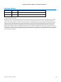
Revision History
Date
Version No.
Revision
06-Apr-2006
1.0
Initial Document Release.
19-Mar-2008
1.1
Updated page size to A4.
Software, hardware, documentation and related materials:
Copyright © 2006 Altium Limited.
All rights reserved. You are permitted to print this document provided that (1) the use of such is for personal use only and will not be copied or
posted on any network computer or broadcast in any media, and (2) no modifications of the document is made. Unauthorized duplication, in
whole or part, of this document by any means, mechanical or electronic, including translation into another language, except for brief excerpts in
published reviews, is prohibited without the express written permission of Altium Limited. Unauthorized duplication of this work may also be
prohibited by local statute. Violators may be subject to both criminal and civil penalties, including fines and/or imprisonment. Altium, Altium
Designer, Board Insight, CAMtastic, CircuitStudio, Design Explorer, DXP, LiveDesign, NanoBoard, NanoTalk, Nexar, nVisage, P-CAD, Protel,
SimCode, Situs, TASKING, and Topological Autorouting and their respective logos are trademarks or registered trademarks of Altium Limited or
its subsidiaries. All other registered or unregistered trademarks referenced herein are the property of their respective owners and no trademark
rights to the same are claimed.
AP0142 (v1.1) March 19, 2008
15