1
MPS2 Digital Sensor
40854,40855,40856
1: Sensor Specifications
Rev: 1.02
Product:
Unit Assembly #s:
MPS-2 Digital Sensor
(All Configurations)
Doc. #:
40854,40855,
40856
Document Type:
1.02
Sensor Specifications
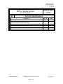
#
Revisions
1 Initial draft of MPS-2 specifications / integrator‟s guide
Multiple revisions to specifications to reflect user manual,
2
some revisions to output value ranges
3 Output waveform capture updated with logic analyzer
4
5
6
Decagon Devices, Inc.
2365 NE Hopkins CT Pullman, WA 99163
Page 1
of 9
REV By
BJW
DRC
Date
4.13.11
4.20.11
DJW
4.21.11
(509) 332-2756
MPS2 Digital Sensor
40854,40855,40856
1: Sensor Specifications
Rev: 1.02
I. Description of Sensor and Measurements
The MPS-2 digital sensor is designed to measure the water potential (soil suction),
and temperature of soil and growing media.
II. Features:
The MPS-2 sensor measures soil water potential and soil temperature. These
fundamental measurements are needed for a variety of plant, water flow, and soil
mechanical stress studies. By combining these measurements into a single sensor, it
allows for more data logger ports to be used for additional environmental
measurements. Water potential is obtained by measuring the dielectric permittivity of
a solid matrix (porous ceramic disc) through the utilization of capacitance/frequency
domain technology. The MPS-2 incorporates high frequency oscillation, allowing the
sensor accurate measurements of water potential in any soil or soilless media with
minimal salinity and textural effects.
III. Measurement Specifications:
Water Potential
Range: -5kPa to -500 kPa (pF 1.71 to pF 3.71)
Resolution: 0.1 kPa
Accuracy: ±20 kPa from -5 to -100 kPa,
*See user manual for more information regard higher kPa accuracies
Temperature
Range: -40°C to 50°C
Resolution: 0.1°C
Accuracy: ±1°C
General
Survival Environment: -40°C to 60°C, 0 to 100% RH
Operating Temperature: 0°C to 50°C (no water potential measurement below 0°C)
Power requirements: 3.6 - 15 VDC, 0.03 mA quiescent, 10 mA max during 150 ms
measurement
Dimensions: 9.6 cm (l) x 3.5 cm (w) x 1.5 cm (d)
Sensor diameter: 3.2 cm
Dielectric Measurement Frequency: 70 MHz
Measurement Time: 150 ms (milliseconds)
Output: RS232 (TTL) with 3.6 volt levels or SDI-12 communication protocol
Connector types: 3.5 mm (stereo) plug or stripped & tinned lead wires (3)
Cable Length: 5m standard; custom cable length available upon request
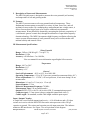
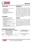
Input / Output Circuitry
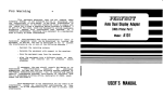
A single line is used for both transmit and receive. A 10 uH inductor and a 510 ohm
resistor are in series with the RXD/TXD line on the microprocessor with a 220 pF
capacitor to ground. The resistor and capacitor provide input protection. The inductor
minimizes RF interference. See Figure 1 for an equivalent circuit diagram.
Decagon Devices, Inc.
2365 NE Hopkins CT Pullman, WA 99163
Page 2
of 9
(509) 332-2756
MPS2 Digital Sensor
40854,40855,40856
1: Sensor Specifications
Rev: 1.02
Figure 1. Equivalent Circuit Diagram. If using multiple sensors on a bus, you may use the equivalent circuit to
simulate the load of additional sensors (up to 62) on a single SDI-12 line.
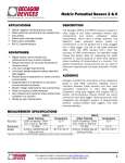
Sensor Excitation
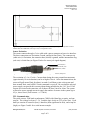
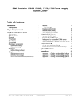
The sensor connects through a 3 wire cable with a stereo connector or bare wire interface.
The three connections are Excitation, Ground, and Serial Out (Data). The connector tip
(white wire) is Excitation, the connector base (shield) is ground, and the intermediate ring
(red wire) is Serial Out (see Figure 2 below for stereo jack signal diagram).
Ground (bare)
Serial Out (red)
Power (white)
Figure 2. Stereo Jack Signal Diagram The signals from base to tip ground, serial out, and power.
The excitation is 3.6 to 15 volts. Current drain during the water potential measurement
(approximately 10 ms in duration) can be as high as 10 mA. After data transmission, the
sensor will pull around 3mA for about 6 seconds. It will then go into a sleep state and
draw around 30uA, until a SDI-12 break command is received. Be sure that the selected
power supply can provide this current without being pulled below the 3.6 V level. If all
sensors are excited at the same time, all of them will draw 10mA for 10ms. The system
will need to source enough current to supply the number of sensors in the system (up to
62), x, times 10mA (Total current = x * 10mA).
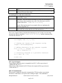
TTL Communication
The serial out uses 1200 baud asynchronous CMOS with 8 data bits, no parity, and one
stop bit. The voltage levels are 0 - 3.6 V and the logic levels are TTL (active low). Each
data byte consists of a start bit (low), 8 data bits (least significant bit first), and a stop bit
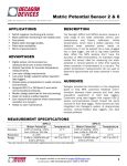
(high), see Figure 3 and 4 for a serial stream example.
Decagon Devices, Inc.
2365 NE Hopkins CT Pullman, WA 99163
Page 3
of 9
(509) 332-2756
MPS2 Digital Sensor
40854,40855,40856
1: Sensor Specifications
Rev: 1.02
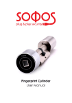
Figure 3. Excitation and serial output stream. Output levels are not absolute. Both excitation and output are zero
initially. Approximately 40 ms after the excitation goes high the serial out line goes high. It stays high for 15 ms, and
then goes low for the start bit of the serial stream. Twelve characters are shown: 100 100 100/r. When the carriage
return character is received the excitation is shut off.
3.5
stop
stop
start
start
3
15 ms high
to start
trans.
Output
2.5
2
1.5
1
start
0.5
0
50
60
70
80
90
100
110
Time (ms)
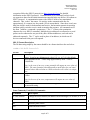
Figure 3. Expansion of first few bits of serial stream from Fig. 1 showing the start and stop bits and the data bits.
Baud rate is 1200, so one byte (8 data bits plus start and stop) takes 0.833 ms. Bytes are transmitted lsb (least
significant bit) first, so the first character, 10001100 represents 00110001 or 0x31 which is ASCII 1. The next
character is 00001100 which is 0x30 or ASCII 0.
TTL Format Description
The data string output by the sensor should be in a format similar to the one below:
<tab>-34.8 22.3<cr>yN<cr><lf>
Section
<tab>
-34.8
22.3
Description
Tab character (0x09) signaling the start of the transmission
Water potential in kPa. Values range approximately from -7 kPa to 110,000 kPa.
Note: in the case of an error, water potential will output an error value of
-9999. The water potential calculation adds a small offset for real water
potential values that calculate to -9999 so that the error value is a unique
case.
Temperature. This number is the temperature of the sensor in degrees
Celsius.
Note: In the case of an error, temperature will output an error value of
Decagon Devices, Inc.
2365 NE Hopkins CT Pullman, WA 99163
Page 4
of 9
(509) 332-2756
MPS2 Digital Sensor
40854,40855,40856
1: Sensor Specifications
Rev: 1.02
-9999.
This carriage return character signals the end of the measurement string
and start of the meta data string.
<cr>
Everything below is this line is meta data:
y
Sensor Type. This character is used to indicate the sensor type. y is used
for the MPS-2 sensor.
N
Checksum. This one character checksum is used in our instruments to
ensure that the data transmitted are valid. The checksum is used for
sections listed above: "<tab>-34.8 22.3<cr>y
<cr><lf>
See the following function for an example of how to implement the
checksum algorithm in C.
The carriage return (0x0d) and line feed (0x0a) are used to signal the end
of the meta data section and the end of the transmission.
Here is an example of how to calculate the checksum (crc) in C. In this case, the string
passed to the function would be: "<tab>-34.8 22.3<cr>y" and the returning value
would be the character „N‟.
char CalculateChecksum(char * Response){
int length, sum = 0, i, crc;
// Finding the length of the response string
length = strlen(Response);
// Adding characters in the response together
for( i = 0; i < length; i++ )
sum += Response[i];
// Converting checksum to a printable character
crc = sum % 64 + 32;
return crc;
}
TTL Typical Outputs
Typical output while the sensor is suspended in air 20°C will be approximately:
-100000 kPa and 20.0 °C.
If the sensor is fully saturated in 20C DI water, the outputs will be approximately:
-8 kPa and 20.0 °C.
SDI-12 Communication
When power is applied to the probe it transmits the TTL data values as previously
discussed. It then enters a low power state waiting for input. The commands it
Decagon Devices, Inc.
2365 NE Hopkins CT Pullman, WA 99163
Page 5
of 9
(509) 332-2756
MPS2 Digital Sensor
40854,40855,40856
1: Sensor Specifications
Rev: 1.02
recognizes follow the SDI-12 protocol (see http://www.sdi-12.org for detailed
information on the SDI-12 protocol). Communication is at 1200 baud, but logic levels
are opposite to those for the initial transmission (start bit high; stop bit low) to conform to
SDI-12 protocol. A communication starts with a SDI-12 break or any transmitted
character. This “wakes” the sensor. No activity on the communication line for
approximately 10 s returns it to sleep mode (30 uA current drain). Since there is only one
data line which is used for both transmit and receive, the host must transmit its message
and then quickly switch to receive mode to monitor the response. All commands are of
the form <address><command><parameters>! The “!” is always the termination
character for every SDI-12 command. Multiple device addresses are allowed so several
probes can be connected to one port if they have different addresses, and each can be
addressed separately. The “?” can be used in place of an address, in which case all
devices connected to the port will respond.
SDI-12 Format Description
The D0 data string output by the sensor should be in a format similar to the one below:
<addr>-34.8+22.3<cr><lf>
Section
<addr>
-34.8
22.3
<cr><lf>
Description
Sensor SDI-12 Address. A one character long SDI-12 address for the
sensor. It can be any alphanumeric value (0-9, a-z, A-Z), 0 is the default
Water potential in kPa. Values range approximately from -7 kPa to 110,000 kPa.
Note: in the case of an error, water potential will output an error value of
-9999. The water potential calculation adds a small offset for real water
potential values that calculate to -9999 so that the error value is a unique
case.
Temperature. This number is the temperature of the sensor in degrees
Celsius.
Note: In the case of an error, temperature will output an error value of
-9999.
This carriage return line feed combination signals the end of the
measurement string
Some Commonly Used SDI-12 Commands:
Command
Description
A<new address>
change the sensor address; an address can be an integer 0..9 or letter, A..Z, a..z
I
returns probe ID
M
measure probe values
D0
return measured values
Decagon Devices, Inc.
2365 NE Hopkins CT Pullman, WA 99163
Page 6
of 9
(509) 332-2756
MPS2 Digital Sensor
40854,40855,40856
1: Sensor Specifications
Rev: 1.02
SDI-12 Examples:
The characters in bold are what was sent to the sensor.
1I!113DECAGON MPS2 108
Identify sensor with address of 1; Return: Sensor Address(1), SDI12 Version (13),
COMPANY (DECAGON), SENSOR TYPE (MPS2), SENSOR VERSION (108)
1M!10012
Measure parameters of sensor with address of 1; Return: sensor address is 1, data are
ready in 001 ms, 2 values will be sent
1D0!1-82.6+21.8
Send the values; Return: sensor address is 1, -82.6 kPa for water potential, 21.8 °C for
temperature
?!0
This returns the sensor address; Return: sensor address is 0
0A1!1
Change the sensor address to 1; Starting address is 0. Return: new sensor address is 1
Decagon Devices, Inc.
2365 NE Hopkins CT Pullman, WA 99163
Page 7
of 9
(509) 332-2756
MPS2 Digital Sensor
40854,40855,40856
1: Sensor Specifications
Rev: 1.02
SDI-12 Compliance:
Decagon‟s SDI-12 sensors recognize all SDI-12 commands outlined in Version 1.3 of the
SDI-12 Protocol (see http://www.sdi-12.org for more detailed information).
Here is a list of differences between the SDI-12 standard and Decagon‟s SDI-12 sensors:
Upon excitation, a TTL string is printed prior to enabling SDI-12 (takes around
75ms).
Parity Bits are ignored.
R & RC Commands return a reading after about 50ms.
Timeout / Power Down is around 5 seconds instead of 100ms.
After Timeout / Power Down, sensors may respond to a break that‟s less than 6.5 ms.
SDI-12 Diagrams:
All sensors must have a unique address. At most 62 sensors can be connected to a single
bus.
Decagon Devices, Inc.
2365 NE Hopkins CT Pullman, WA 99163
Page 8
of 9
(509) 332-2756
MPS2 Digital Sensor
40854,40855,40856
1: Sensor Specifications
Rev: 1.02
Decagon Devices, Inc.
2365 NE Hopkins CT Pullman, WA 99163
Page 9
of 9
(509) 332-2756