1
MPS2 Digital Sensor
40854,40855,40856
1: Sensor Specifications
Rev: 1.02
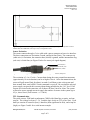
Figure 1. Equivalent Circuit Diagram. If using multiple sensors on a bus, you may use the equivalent circuit to
simulate the load of additional sensors (up to 62) on a single SDI-12 line.
Sensor Excitation
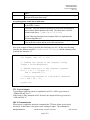
The sensor connects through a 3 wire cable with a stereo connector or bare wire interface.
The three connections are Excitation, Ground, and Serial Out (Data). The connector tip
(white wire) is Excitation, the connector base (shield) is ground, and the intermediate ring
(red wire) is Serial Out (see Figure 2 below for stereo jack signal diagram).
Ground (bare)
Serial Out (red)
Power (white)
Figure 2. Stereo Jack Signal Diagram The signals from base to tip ground, serial out, and power.
The excitation is 3.6 to 15 volts. Current drain during the water potential measurement
(approximately 10 ms in duration) can be as high as 10 mA. After data transmission, the
sensor will pull around 3mA for about 6 seconds. It will then go into a sleep state and
draw around 30uA, until a SDI-12 break command is received. Be sure that the selected
power supply can provide this current without being pulled below the 3.6 V level. If all
sensors are excited at the same time, all of them will draw 10mA for 10ms. The system
will need to source enough current to supply the number of sensors in the system (up to
62), x, times 10mA (Total current = x * 10mA).
TTL Communication
The serial out uses 1200 baud asynchronous CMOS with 8 data bits, no parity, and one
stop bit. The voltage levels are 0 - 3.6 V and the logic levels are TTL (active low). Each
data byte consists of a start bit (low), 8 data bits (least significant bit first), and a stop bit
(high), see Figure 3 and 4 for a serial stream example.
Decagon Devices, Inc.
2365 NE Hopkins CT Pullman, WA 99163
Page 3
of 9
(509) 332-2756