1
Installation, use
andmaintenance manual
GAHP Line AR Series
Air-Water reversible absorption heat pumpsfor heating and
cooling medium-large areas
powered by gas and renewable energy
Revision: H
Code: D-LBR270
This manual has been drawn up and printed by Robur S.p.A.; whole or partial reproduction of
this manual is prohibited.
The original is filed at Robur S.p.A.
Any use of this manual other than for personal consultation must be previously authorised by
Robur S.p.A.
The rights of those who have legitimately filed the registered trademarks contained within this
publication are not affected.
With the aim of continuously improving the quality of its products, Robur S.p.A. reserves the
right to modify the data and contents of this manual without prior notice.
Installation, use andmaintenance manual – GAHP Line AR Series
Index of contents
1PREFACE������������������������������������������������������������������������������������������������������������4
2SAFETY WARNINGS������������������������������������������������������������������������������������������5
3OVERVIEW AND TECHNICAL FEATURES��������������������������������������������������������7
3.1GENERAL INFORMATION������������������������������������������������������������������������������������������������������������������������������������������������������������ 7
3.2NOTES ON OPERATION OF THE APPLIANCE������������������������������������������������������������������������������������������������������������������������ 9
3.3TECHNICAL MANUFACTURING CHARACTERISTICS��������������������������������������������������������������������������������������������������������10
3.4TECHNICAL DATA������������������������������������������������������������������������������������������������������������������������������������������������������������������������11
3.5DIMENSIONS AND SERVICE PANEL���������������������������������������������������������������������������������������������������������������������������������������13
4NORMAL OPERATION������������������������������������������������������������������������������������14
4.1START UP (AND SHUT DOWN)������������������������������������������������������������������������������������������������������������������������������������������������14
4.2ON-BOARD ELECTRONICS��������������������������������������������������������������������������������������������������������������������������������������������������������15
4.3RESET OPERATIONS AND MANUAL DEFROSTING�����������������������������������������������������������������������������������������������������������18
4.4OPERATING SETTINGS���������������������������������������������������������������������������������������������������������������������������������������������������������������20
4.5PROLONGED PERIODS OF DISUSE����������������������������������������������������������������������������������������������������������������������������������������20
5HYDRAULIC INSTALLATION��������������������������������������������������������������������������22
5.1GENERAL INSTALLATION PRINCIPLES����������������������������������������������������������������������������������������������������������������������������������22
5.2POSITION OF THE APPLIANCE������������������������������������������������������������������������������������������������������������������������������������������������22
5.3HYDRAULIC CONNECTIONS����������������������������������������������������������������������������������������������������������������������������������������������������25
5.4GAS SUPPLY����������������������������������������������������������������������������������������������������������������������������������������������������������������������������������29
5.5FILLING OF HYDRAULIC CIRCUIT�������������������������������������������������������������������������������������������������������������������������������������������30
5.6EXHAUST FLUE GAS��������������������������������������������������������������������������������������������������������������������������������������������������������������������31
5.7PROGRAMMING OF HYDRAULIC PARAMETERS���������������������������������������������������������������������������������������������������������������32
6ELECTRICAL INSTALLATION��������������������������������������������������������������������������35
6.1CONNECTING THE APPLIANCE TO THE MAINS�����������������������������������������������������������������������������������������������������������������37
6.2ELECTRICAL CONNECTIONS FOR THE SYSTEM CIRCULATOR��������������������������������������������������������������������������������������40
6.3CONNECTIONS FOR CONSENT SWITCH OPERATION������������������������������������������������������������������������������������������������������43
6.4USE OF THE DIRECT DIGITAL CONTROLLER�����������������������������������������������������������������������������������������������������������������������44
6.5HOW TO RESET THE FLAME CONTROLLER FROM REMOTE������������������������������������������������������������������������������������������54
7INITIAL ACTIVATION AND MAINTENANCE��������������������������������������������������57
7.1PROCEDURE FOR FIRST START UP�����������������������������������������������������������������������������������������������������������������������������������������57
7.2MAINTENANCE�����������������������������������������������������������������������������������������������������������������������������������������������������������������������������61
7.3CHANGE OF GAS TYPE��������������������������������������������������������������������������������������������������������������������������������������������������������������63
8ACCESSORIES��������������������������������������������������������������������������������������������������65
9OPERATING CODES/TROUBLESHOOTING���������������������������������������������������66
9.1OVERVIEW AND OPERATING CODES/TROUBLESHOOTING������������������������������������������������������������������������������������������66
����������������������������������������������������������������������80
DE
3
1PREFACE
This "Installation, use andmaintenance manual" is a guide to the installation and operation of the gas absorption reversible heat pump of the GAHP Line AR Series.
This manual is specifically intended for:
• final users for the operation of the appliance according to their own
requirements;
• Installation technicians (hydraulic and electrical) for a correct installation of the
appliance.
The manual also contains:
• a section that describes all the operations necessary for the “first start-up” and for
the “gas change” of the appliance, as well as the main maintenance operations;
• an "ACCESSORIES" section with a description of accessories available and their respective reference codes;
• (IN CASE) one or more APPENDIX sections in which are reported some "specific"
information for a particular country.
Definitions, meaning of terms and icons
APPLIANCE: this term indicates the gas absorption reversible heat pump of the GAHP
Line AR Series.
CCI: "Comfort Control Interface" device. Not applicable.
DDC: digital control panel (Direct Digital Controller).
TAC: Technical Assistance Centre (authorised by Robur S.p.A.).
ACS: sanitary (domestic) hot water.
UTA: air handler.
The icons used in the manual have the following meanings:
= DANGER
= WARNING
= NOTE
= START OF OPERATING PROCEDURE
= REFERENCE to another part of the manual or other document
4
Installation, use andmaintenance manual – GAHP Line AR Series
2SAFETY WARNINGS
Packing items (plastic bags, polystyrene foam, nails, etc.) must be kept out of the reach of
children, as they are potentially dangerous.
The appliance must only be used for the purposes for which it has been designed. Any
other use is considered inappropriate and therefore dangerous. The manufacturer does
not accept any contractual or extra-contractual liability for any damage caused by improper use of the appliance.
The appliance is not intended to be used by persons (including children) whose physical,
sensory and mental capacities are impaired, or who lack the necessary experience and
knowledge, unless they are supervised or instructed in its use by persons responsible
for their safety. Children must be supervised to ensure that they do not play with the
appliance.
The unit uses a water/ammoniac absorption cycle for hot/cold water production. The ammoniac is in water solution inside a sealed circuit tested for tightness by the manufacturer. In case of coolant leaks, switch off the electrical power and gas supplies only if this
can be done in total safety. Contact your Authorised Service Centre.
Frequent topping up of the hydraulic with water can result in damage due to scale and
corrosion, depending on the quality of the water being used. Make sure the system is
water tight and that the expansion tank is operational.
Concentrations of chlorides or free chlorine in the circuit above the values given in Table
5.1 Chemical and physical parameters of water → 25 will damage the unit's water/ammonia exchanger.
Close the gas supply before working on the gas circuit. On completing work on the gas
circuit, check for leakages as required by established regulations.
Do not operate the appliance if dangerous conditions exist: odour of gas in the grid
or near the appliance; problems with the electrical/gas grid or hydraulic circuit; parts
of the appliance submerged in water or otherwise damaged; controls or safety components bypassed or defective. In these cases, ask for assistance to professionally qualified
personnel.
If you smell gas:
•
•
•
o not use electrical devices such as telephones, multimeters or other equipment
d
that can cause sparks next to the appliance;
shut off gas supply closing the isolation valve;
cut off electrical power opening the main breaker upstream of the appliance (to be
provided by the electrical installer in an appropriate panel);
5
•
a sk for assistance to professionally qualified personnel from a telephone distant
from the appliance.
Moving parts, also during the appliance's start-up and shut-down cycles. Do not remove
guards. Make sure the appliance cannot be started up inadvertently.
POISONING HAZARD
Make sure the flue gas components are tight and compliant with established regulations.
After any intervention on these parts, check for tightness.
BURN HAZARD
The appliance contains numerous hot parts. Do not open up the appliance or touch the
fumes outlet pipe. If necessary, contact your Technical Assistance Centre.
The appliance has a sealed circuit classified as pressure equipment, i.e. with internal pressure higher than atmospheric pressure. The fluids contained in the sealed circuits are
harmful if swallowed or inhaled, or if they come into contact with the skin. Do not carry
out any operation on the sealed circuit or on its valves.
ELECTROCUTION HAZARD
•
•
•
se only approved components for the electrical connections, as specified by the
U
manufacturer.
Disconnect the electrical power supply before working on the appliance's internal
electrical equipment (electrical panel, motors, control board, etc.).
Make sure the appliance cannot be started up inadvertently.
The electrical safety of the appliance is ensured only when it is correctly connected to an
efficient grounding system, compilant with current safety regulations.
DAMAGE DUE TO AGGRESSIVE SUBSTANCES IN THE AIR SUPPLY
Hydrogenated hydrocarbons, which contain chlorine and fluorine compounds, will increase the corrosion of the unit.
Make sure the air supply is free of aggressive substances.
EXPLOSIVE/FLAMMABLE MATERIALS HAZARD
Do not use or store flammable materials (paper, solvents, paint, etc.) in the vicinity of the
appliance.
RECOMMENDATION. Stipulate a maintenance contract with an authorised specialist
contractor for the annual inspection of the appliance and maintenance when needed.
Maintenance and repairs may only be done by a contractor legally authorised to work on
gas appliances and equipment. Use only original spare parts.
6
Installation, use andmaintenance manual – GAHP Line AR Series
3OVERVIEW AND TECHNICAL FEATURES
In this section you will find general information, hints on the operating principle of the
appliance and its manufacturing features. This section also contains technical data and
dimensional drawings of the appliance.
3.1GENERAL INFORMATION
This manual is an integral and essential part of the product and must be delivered to the
user together with the appliance.
Conformity to CE standards
The gas absorption reversible heat pumps of the GAHP Line AR Series are certified as
conforming to EC standard and comply with the essential requirements of the following
Directives:
• Gas Directive 90/396/EEC and subsequent modifications and additions.
• Efficiency Directive 92/42/EEC and subsequent modifications and additions.
• Electromagnetic Compatibility Directive 89/336/EEC and subsequent modifications and additions.
• Low Voltage Directive 89/336/EEC and subsequent modifications and additions.
• Pressurised Equipment Directive 97/23/EEC and subsequent modifications and
additions.
Information regarding the above EC certifications is given in Paragraph 3.4 TECHNICAL
DATA → 11as well as on the Nameplate of the appliance itself.
Installation and regulatory references
When the appliance arrives at the installation site, before beginning the stages required
to move it in order to position it on the site, perform a visual check to ascertain that there
are no evident signs of breakage or damage to the packaging or to the external panels,
which would be signs that damage occurred during transport.
Packing materials must be removed only after the appliance has been positioned on site.
After removing the packing materials, ensure that the appliance is intact and complete.
Installation of the appliance may only be carried out by professionally qualified personnel
by i.e. firms qualified according to the current legislation of the country of installation.
"Professionally qualified personnel" means personnel with specific technical competence
in the sector of heating/cooling installations and gas appliances.
Installation of the appliance must be carried out in compliance with current local and
national regulations regarding the design, installation and maintenance of heating and
cooling plants in accordance with the manufacturer's instructions.
In particular, current regulations regarding the following aspects must be respected:
• Gas equipment.
• Electrical equipment.
• Refrigeration plants and heat pumps.
• Every other standard and regulation concerning the installation of equipment for
summer and winter air conditioning using gas fuel.
The manufacturer does not accept any contractual or extra-contractual liability for any
damage caused by errors in installation and/or failure to observe the abovementioned
regulations and the instructions supplied by the manufacturer itself.
7
Once the appliance is installed
The installer must provide the owner with a Declaration stating that the installation has
been completed in compliance with state-of-the-art practices, current national and local
regulations, and recommendations by the manufacturer.
Before contacting your authorised Robur Technical Assistance Centre (TAC) for the initial
activation, the firm must ensure that:
• the electricity and gas mains specifications correspond to the specifications on the
nameplate;
• the pressure of the gas supplied falls within the range of values specified by the
manufacturer;
• the gas supplied to the appliance is of the type for which it is designed;
• the gas supply system and water distribution system are sealed;
• the gas and electricity supply systems are correctly rated for the capacity required
by the appliance and that they are equipped with all safety and control devices
prescribed by current regulations.
Check that no safety and control devices are excluded, by-passed or not properly
working.
Initial activation procedure
The entire procedure for the first activation of the appliance must be carried out exclu
sively by an authorized Robur Technical Assistance Centre (TAC) and according to the
instructions supplied by the manufacturer.
To carry out entire procedure correctly, follow the instructions in Paragraph 7.1 PROCEDURE FOR FIRST START UP → 57.
Contact your local Authorised Robur Technical Assistance Centre (TAC). To find out who
your local TAC is, contact Robur S.p.A. (tel. +39 035 888.111). The guarantee could be
voided if the initial activation is not carried out (and validated) by a Robur TAC.
Operation and maintenance of the appliance
To ensure the correct operation of the appliance and to avoid failures, control of the
switching on and off of the appliance must be carried out exclusively via a switch located
on the on/off command circuit.
If the appliance is to be connected to a Direct Digital Controller (DDC, available as an accessory), control of activating and deactivating the appliance must be performed exclusively through the DDC itself.
In conditions of correct operation of the appliance, it absolutely must not be switched on
and off by removing power upstream from the on/off commands (DDC or other switch)
before having operated these first and waiting for the shutdown cycle to end (approximately 7 minutes).
If the appliance fails to operate correctly, with the consequent indication of the Machine code, follow the instructions of Paragraph 9.1 OVERVIEW AND OPERATING CODES/
TROUBLESHOOTING → 66.
In the event of failure of the appliance and/or breakage of any component, do not attempt to repair and/or restore operation; proceed as follows:
8
Installation, use andmaintenance manual – GAHP Line AR Series
•
eactivate the appliance immediately (if permitted and if no condition of danger
d
exists) by starting the shutdown cycle via the CCP (or DDC or consent switch) and
waiting for it to terminate (approximately 7 minutes);
• disconnect the appliance from the gas and electricity mains, cutting off gas supply
by means of the appropriate valve and the power supply by means of the external
circuit breaker provided by the electrical system installation technician on the appropriate panel.
If it is decided not to use the appliance for a prolonged period, disconnect the appliance following the instructions provided in Paragraph 4.5 PROLONGED PERIODS OF
DISUSE → 20.
Correct routine maintenance ensures the efficiency and good operation of the appliance
over time.
Carry out maintenance operations according to the instructions supplied by the
manufacturer.
For maintenance of the appliance's internal components, contact a Robur TAC
or qualified technician; for other maintenance requirements, see Paragraph 7.2
MAINTENANCE → 61.
Any repair of the appliance must be carried out by an authorised Robur Technical Assistance Centre (TAC), using only original parts.
Failure to observe the indications given above may compromise the operation and safety
of the appliance, and may invalidate its guarantee, if active.
If the appliance is to be disposed of, contact Robur S.p.A. for its correct disposal.
If the appliance is to be sold or transferred to another owner, ensure that this “Installation, use andmaintenance manual" is handed over to the new owner and installation
technician.
3.2NOTES ON OPERATION OF THE APPLIANCE
The appliance powered by 230 V 1N 50 Hz electrical power - .
During operation, combustion products are exhausted via the discharge terminal at the
left side of the appliance, with outlet in a vertical position.
Control and management of operation of the appliance occurs via the on-board electronics through the microprocessor control board (see Figure 4.1 → 16).
Control and management of operation of the appliance may also take place via the Direct
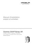
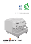
Digital Controller (see Figure 3.1 CCI/DDC → 10) available as an accessory.
For instructions regarding the use, configuration and programming of the DDC, refer to
the two manuals supplied with the unit.
DDC configuration/programming operations must be carried out by an authorised Robur
Technical Assistance Centre (TAC) during initial activation procedures and according to
the instructions supplied by the manufacturer.
9
Figure 3.1 – CCI/DDC
Description and general characteristics
The appliance is able to produce hot water to +60°C or chilled water to a temperature of
3°C, operating at extremely high efficiency in heat pump mode.
The appliance is supplied with helicoidal motor-fan or available in reduced-noise versions ("S", with helicoidal motor-fan with larger blades) for reduced noise emissions.
Operating principle
• When operating in cooling mode (in summer) the appliance operates as an absorption chiller, and the heat, taken away from the cooled environment via the
HYDRAULIC CIRCUIT, is dissipated towards the outside via the air-cooled FINNED
COIL.
• When operating in heating mode (in winter) the appliance makes use of the absorption cooling cycle to recover heat from the outside environment via the FINNED
COIL which, added to the heat produced by the combustion of natural/L.P.G. gas,
is transferred into the EXCHANGER and then into the environment to be heated,
ensuring efficiency of 140 % (under nominal conditions).
The appliance is not designed for performing frequent inversions of functional mode (heating / cooling). 100 inversions per year is the maximum permitted, not to be exceeded.
3.3TECHNICAL MANUFACTURING CHARACTERISTICS
The appliance is supplied with the following technical manufacturing characteristics,
control and safety components:
• Steel sealed circuit, treated on the outside with epoxy paint;
• Multigas pre-mixing burner equipped with ignition and flame detection managed
by an electronic control unit;
• Air-based heat exchanger with single-position finned coil, manufactured in steel
tubing and aluminium fins;
• Titanium stainless steel tube bundle water exchanger, with external insulation;
• Inversion valve on the cooling circuit, for use of the appliance in heating or cooling
mode;
• Automatic two-way microprocessor-controlled defrosting valve, allowing the
finned coil to be defrosted;
• Variable-flow microprocessor-controlled helicoidal motor-fan (summer
operation).
Control and safety components
• S61 electronic board with microprocessor integrated with LCD display and encoder (in Figure 4.1 → 16).
10
Installation, use andmaintenance manual – GAHP Line AR Series
•
•
•
•
•
•
•
•
•
•
•
S atellite electronic board AR11 (in Figure 4.2 → 16).
Plant water flowmeter.
Sealed circuit high temperature limit thermostat, with manual reset.
Differential exhaust gas manostat on the combustion circuit.
Automatically resettable exhaust gas temperature thermostat.
Sealed circuit safety relief valve.
Safety by-pass valve, between high and low pressure parts of the sealed circuit.
Antifreeze functions for hydraulic circuit.
Ionization flame control box.
Double shutter electric gas valve.
Direct Digital Controller (DDC) with LCD display and encoder (in Figure 3.1 CCI/
DDC → 10).
3.4TECHNICAL DATA
Table 3.1 – Technical characteristics
GAHP-AR S
OPERATION WHEN HEATING
G.U.E. gas usage efficiency
Thermal capacity
Hot water delivery temperature
Hot water return temperature
Thermal power
Hot water flow rate
Hot water pressure drop
Ambient air temperature (dry bulb)
Nominal (1013 mbar - 15°C)
maximum
nominal
maximum
minimum temperature in
continuous operation**
nominal
nominal (Delta T = 10 °C)
maximum
minimum
at nominal water flow
nominal
maximum
minimum
nominal (Delta T = 5 °C)
maximum
minimum
at nominal water flow
nominal
maximum
minimum
maximum
minimum
OPERATING IN COOLING MODE
G.U.E. gas usage efficiency
Cooling output
Water flow rate
Internal pressure drop
External air temperature
Inlet cold water temperature
GAHP-AR
%
kW
°C
°C
°C
140 (1)
25,70
60
50
50
°C
20
kW
l/h
l/h
l/h
bar
°C
°C
°C
35,30 (1)
3040
5000
1400
0,29 (2)
7
35
-20
%
kW
l/h
l/h
l/h
bar
°C
°C
°C
°C
°C
67 (1)
16,90 (1)
2900
3200
2500
0,31 (2)
35
45
0
45
6
V
230
single-phase
ELECTRICAL SPECIFICATIONS
Power supply
Voltage
TYPE
Frequency
Electrical power absorption
Degree of protection
INSTALLATION DATA
gas consumption
NOx emission class
NOx emission
CO emission
Level of acoustic pressure at 10 meters (maximum)
Maximum operating pressure
Water content inside the apparatus
nominal
IP
methane G20 (nominal)
G25 (nominal)
G30 (nominal)
G31 (nominal)
50 Hz
supply
kW
50
0,93 (6)
0,90 (6)
X5D
m3/h
m3/h
kg/h
kg/h
ppm
ppm
dB(A)
bar
l
2,72 (3)
3,16 (5)
2,03 (4)
2,00 (4)
5 (9)
30 (9)(10)
23 (9)(10)
49 (7)
54 (7)
4
3
11
GAHP-AR S
Water fitting
Gas fitting
Fume outlet
Size
Weight
GENERAL INFORMATION
INSTALLATION MODE
TYPE
thread
TYPE
thread
Diameter (∅)
width
height
depth
In operation
AMMONIA R717
WATER H2O
COOLING FLUID
MAXIMUM PRESSURE OF THE COOLING CIRCUIT
** in transient operation, lower temperatures are allowed
"G
"G
mm
mm
mm
mm
kg
GAHP-AR
F
1"1/4
F
3/4"
80
850
1540 (8)
1290 (8)
1230
390
380
B23, B53
7,5
10,0
35
kg
kg
bar
Notes:
1. As per EN12309-2 evaluated on actual thermal capacity. For operating conditions
other than nominal, refer to the Design Manual.
2. For flow rates different from the nominal refer to the Design Manual.
3. PCI 34.02 MJ/m3 (1013 mbar – 15 ° C).
4. PCI 46.34 MJ/kg (1013 mbar – 15 ° C).
5. PCI 29.25 MJ/m3 (1013 mbar – 15 ° C).
6. ± 10% depending on power voltage and absorption tolerance of electric motors.
7. Free field, frontal, directionality factor 2.
8. Overall dimensions excluding fumes pipes (see Figure 3.2 GAHP-AR
dimensions → 13).
9. All values measured with G20 (natural gas) as reference gas.
10. NOx and CO values are measured referring to EN 483 (combustion values at 0%
O2).
PED characteristics
The technical characteristics given below regard the parameters required by the Pressure
Equipment Directive (PED) for the sealed circuit present on each appliance.
Table 3.2 – PED data
GAHP-AR S
GAHP-AR
PED data
COMPONENTS UNDER PRESSURE
TEST PRESSURE (IN AIR)
SAFETY VALVE PRESSURE CALIBRATION
FILLING RATIO
"SEALED SYSTEM" TARE
FLUID GROUP
12
Generator
Leveling chamber
Evaporator
Cooling volume transformer
Cooling absorber solution
Solution pump
l
l
l
l
l
l
bar g
bar g
kg of
NH3/l
kg
18,6
11,5
3,7
4,5
6,3
3,3
55
35
0,157
245
GROUP 1°
Installation, use andmaintenance manual – GAHP Line AR Series
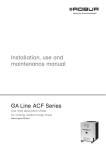
3.5DIMENSIONS AND SERVICE PANEL
1290
Figure 3.2 – GAHP-AR dimensions
LEGEND
APosition of holes for fixing of anti-vibration joints
BH = 1545 mm for "S" version (reduced-noise)
Front and right side views (dimensions in mm)
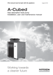
Figure 3.3 – GAHP-AR service plate
LEGEND
GGas connection
D. 3/4" F
AOutlet water
D. 1-1/4" F
BInlet water D. 1-1/4" F
Detail of hydraulic and gas connections (dimensions in mm)
13
4NORMAL OPERATION
In this section you will find all the indications necessary for the activation, regulation and
control of operation of the appliance via the controller present in the electrical panel.
4.1START UP (AND SHUT DOWN)
Efficient operation and long life of the appliance depend largely on its correct use!
Before activating the appliance, check that:
• the gas valve is open;
• the appliance is powered electrically: the general electrical switch (GS) must be in
the «ON» position;
• the installation technician has ensured that the hydraulic circuit is supplied in the
correct conditions.
If these conditions are satisfied, it is possible to proceed with activation.
If the appliance is connected to a DDC running in controller mode, the appliance is started up and controlled exclusively by the DDC.
If the appliance is not connected to a DDC, it may be activated and deactivated only by
means of the on/off commands provided by the electrical installation technician.
According to requirements, these on/off commands may be:
• An on/off switch for activation and deactivation of the appliance. This switch may
be an on/off button, an ambient thermostat, a programmable timer, or one or more
clean contacts controlled by another process;
• A summer/winter selector switch, for selecting the operating mode of the appliance (cooling or heating).
For details about the type of on/off command installed, contact the plant’s electrical installation technician.
Start up
Select the operating mode required (cooling or heating) by means of the summer/winter
selector switch, if the mode desired is not already selected.
Switch on the appliance by means of the on/off command (placing it in the "ON"
position).
During operation of the appliance, the summer/winter switch (from summer to winter
operation and vice versa, or so-called "cycle inversion") may require a maximum of 11
minutes from the time this inversion is invoked by the user.
Shut down
Switch off the appliance via the on/off command (placing it in the "OFF" position).
The shutdown cycle takes approximately 7 minutes to complete.
The on/off commands are essential. Do not switch the appliance on or off by connecting
it to or disconnecting it from the power supply directly, as this may be a source of danger
and in any case damage the appliance or the plants connected to it.
14
Installation, use andmaintenance manual – GAHP Line AR Series
For instructions regarding the use of the DDC, refer to the two manuals supplied with it,
and in particular: "Final user manual - manual 2"
Visualising and clearing of operating codes
Operating codes can be generated by the controller or by the DDC.
The operating codes generated by the controller are visualised on its display and may
also be visualised on the display of the DDC (if fitted).
Operating codes generated by the controller can be reset with the controller itself or
from the DDC (if fitted or where possible).
If these codes arise, it is necessary to follow the instructions in Paragraph 9.1 OVERVIEW
AND OPERATING CODES/TROUBLESHOOTING → 66.
For a description of the operating codes generated by the electronic board and how to
reset them, refer to the list of operating codes contained in Table 9.1 TABLE OF OPERATING CODES generated by the S61 electronic board (firmware version 3.021) → 66.
The controller (see Figure 4.1 → 16) is located inside the electrical panel of the appliance
and the display may be viewed through the viewing hole on the front panel of the unit
itself.
The Machine Codes generated by the DDC may only be viewed on the display of the DDC
and may be cleared only through the DDC.
Operating codes generated by the electronic board during the start-up of the
appliance
If the appliance remains inactive for a prolonged period, it is possible that air is present in
the gas pipes.In this case, activation fails and the appliance reports the operating code:
"u_12" - flame controller arrest (temporary) (see Table 9.1 TABLE OF OPERATING CODES
generated by the S61 electronic board (firmware version 3.021) → 66) and after a brief
interval the appliance automatically launches the start up procedure again.
If code (u_12) is signalled 3 times on successive activation attempts, the code persists, the
appliance locks out the flame controller and displays the following operating code: "E_12"
- flame controller arrest (see Table 9.1 TABLE OF OPERATING CODES generated by the S61
electronic board (firmware version 3.021) → 66). In this case reset is not automatic.
To restore operation of the appliance, carry out a reset of the flame control unit via menu
2 of the controller: the procedure is illustrated in Paragraph 4.3 RESET OPERATIONS AND
MANUAL DEFROSTING → 18. After it is reset, the appliance will make a new attempt to
activate.
If the appliance locks out several times, contact a Robur TAC by calling the office Technical
Service of Robur S.p.A. (tel. 035 888.111).
When activation is successful, the appliance is managed by the on-board controller (see
following paragraph).
4.2ON-BOARD ELECTRONICS
The following descriptions refer to the S61 controller with firmware version 3.021.
The appliance is fitted with an S61microprocessor controller interconnected with an AR11
satellite board, located on the side of the S60 board itself.
The S61 controller controls the appliance and displays data, messages and operating
codes. Programming, control and monitoring of the appliance take place by interacting
15
with the display and knob. The CAN BUS port connects one or several appliances to the
Comfort Control Panel.
The AR11 satellite board is used for connecting the inversion valve and the defrosting
valve.
Figure 4.1
LEGEND
Controller S61
(in every unit)
Electronic board S61
Figure 4.2
LEGEND
Satellite controller AR11
(only in GAHP-AR unit)
Eletronic board AR11
With appliance connected to a DDC: if the DDC in controller mode, activation and deactivation of the appliance must be carried out exclusively via DDC; if the DDC in "monitor"
mode, control of the switching on and off must be carried out exclusively via the switches
fitted by the electrical installation technician.
For instructions regarding the use of the DDC, refer to the two manuals supplied with it,
and in particular: "Final user manual - manual 2"
Description of menu of S61 controller
The parameters and settings of the appliance are grouped in the menus shown on the
controller’s display:
16
Installation, use andmaintenance manual – GAHP Line AR Series
Table 4.1 – Menu of electronic board
MENU
MENU DESCRIPTION
Menu 0
VIEW DATA (TEMPERATURE, VOLTAGE, PUMP SPEED, ECC...)
Menu 1
VIEW ALL PARAMETERS
Menu 2
ENTER ACTIONS
Menu 3
USER SETTINGS (THERMOSTATING, SET-POINT, T. DIFFERENTIAL)
Menu 4
INSTALLATION TECHNICIAN SETTINGS
Menu 5
TECHNICAL ASSISTANCE CENTRE SETTINGS
Menu 6
TECHNICAL ASSISTANCE CENTRE SETTINGS (MACHINE TYPE)
Menu 7
VIEW DIGITAL IMPUTS
Menu 8
(MENU NOT USED)
E
EXIT MENU
Menu list of electronic board
THE DISPLAY SHOWS
0.
1.
2.
3.
4.
5.
6.
7.
8.
E.
Menus 0, 1 and 7 are Viewing Menus: they only allow the information displayed to be
read, and not modified. Menu 0 shows the appliance operating data in real time. Menu 1
shows the parameters that characterise the operation of the appliance and their current
values.
Menu 7 is to be used ONLY by the Robur TAC.
To view the information contained in these menus, proceed as illustrated in the procedure explained below: HOW TO ACCESS THE MENUS.
Menu 2 is an execution menu: it allows the operations of resetting the flame control unit,
error reset and the manual defrosting command to be performed.
To perform these procedures, see Paragraph 4.3 RESET OPERATIONS AND MANUAL
DEFROSTING → 18
Menu 3 is a settings menu: it allows the values displayed to be set. The correct values of
these parameters, for optimum performance of the appliance with the plant to be used
connected, have already been set during installation. In any case, to set new values for
the parameters, see Paragraph 5.7 PROGRAMMING OF HYDRAULIC PARAMETERS → 32
Menus 4, 5, 6 and 7 exclusively concern the installation technician and Robur’s authorized Technical Assistance Centre.
Menu 8 may currently be selected, but not used.
Display and knob
The controller’s display can be viewed through the glass of the viewing aperture on the
front panel of the appliance.
Upon activation, all display’s LED’s light up, and then the name of the controller displays. Subsequently (if the on/off command switch is set to ON), the appliance begins to
operate.
During correct operation the display shows, alternately, the following information: outlet
water temperature, inlet water temperature, and the difference between the two water
temperatures (see Table 4.2 Operating information → 17 where is displayed an example
of a operating cooling mode).
Table 4.2 – Operating information
OPERATING MODE: COOLING
PARAMETER
Cold inlet water temperature
Cold outlet water temperature
Differential temperature (outlet - inlet)
Example of data visualised on display: water temperature and differential
THE DISPLAY SHOWS
12.0
7.0
5.0
If there are operating problems, the display shows, sequentially, the operating codes corresponding to the problem detected. A list of these codes with their description and the
17
procedure to follow to bring the appliance back to correct operation is provided in Paragraph 9.1 OVERVIEW AND OPERATING CODES/TROUBLESHOOTING → 66.
The knob is used to display or set parameters, or to execute actions/commands (e.g.: a
function or reset), when permitted.
HOW TO ACCESS THE MENUS
• To use the knob with the special key supplied with the appliance:
You will need: the appliance’s electrical power switches set to “ON”; the controller’s display sequentially shows the operating data (temperature, delta T°) regarding the current
mode (e.g.: heating) and any active operating codes ("u/E...").
1. R
emove the front panel by removing the fixing screws.
2. Remove the cover of the electrical panel to access the knob.
3. Use the special key through the hole to operate the knob and access the controller’s menus and parameters.
4. To display the menus just press the knob once: the display shows the first menu:
"0." (= menu 0).
5. The display shows “0.”. To display the other menus, turn the knob clockwise; The
display will read, in order: "1.", "2.", "3.", "4.", "5.", "6.", "7.", "8." and "E" (see 4.1 Menu of
electronic board → 17).
6. To display the parameters in a given menu (for example, menu 0), turn the knob
until it displays the menu in question (in the example: "0.") and press the knob: the
display will show the first of the menu’s parameters, in this example "0.0" or "0.40"
(= menu 0, parameter "0" or "40").
7. In the same way: turn the knob to scroll through content (menus, parameters, actions), press the knob to select/confirm the content (access a menu, display/set
a parameter, execute an action, quit or return to the previous level). For example,
to quit the menus, turn the knob to scroll through menus "0.", "1.", "2." etc. until the
controller displays the quit screen "E"; now press the knob to quit.
In the case of menus 0 and 1, the user can view any parameter. For how to access to menu
2, refer to Paragraph 4.3 RESET OPERATIONS AND MANUAL DEFROSTING → 18. To set the
parameters of menu 3, refer to Paragraph 5.7 PROGRAMMING OF HYDRAULIC PARAMETERS → 32. The other menus are not for the User: the information in these menus is dealt
with in the sections dedicated to the installation technician or Robur TAC.
The special key allows the knob of the electronic board to be operated without opening
the cover of the electrical panel, so that operators are protected from live components.
When the necessary settings have been completed, put away the special key, replace the
cap on the aperture of the electrical panel and refit the front panel of the appliance.
4.3RESET OPERATIONS AND MANUAL DEFROSTING
There are several possible reasons why the appliance may have error status and therefore
its operation arrested; such an error situation does not necessarily correspond to damage
or malfunction on the part of the appliance. The cause that has generated the error may
be temporary: for example, presence of air in the gas supply line or temporary power
failure.
The appliance can be reset with S61 controller menu 2, or the DDC (if present) (in this latter cases, refer to their documentation).
18
Installation, use andmaintenance manual – GAHP Line AR Series
Reset appliance controller
The items available in menu 2 through which it is possible to perform the actions permitted are: 0 (execution of flame control unit reset) and 1 (execution of board error reset);
selecting E quits the menu (see Table 4.3 Menu 2 → 19).
For regulatory reasons, the flame controller reset is in a dedicated menu (2. 0).
Table 4.3 – Menu 2
MENU OPTION
NECESSARY TO
0
Reset flame controller arrest
1
Reset altri errori
22
Manual defrost
E
(EXIT MENU)
Menu reset operation and manual defrosting
SHOWN ON DISPLAY AS
2. 0
2. 1
2. 22
2. E
ACTION 0: reset flame controller arrest; this may be used when the appliance is first activated, see Paragraph 4.1 START UP (AND SHUT DOWN) → 14; or after a long period of
disuse, see Paragraph 4.5 PROLONGED PERIODS OF DISUSE → 20.
You will need: access to the electrical panel, see Paragraph “Display and knob”.
To reset the flame control unit select menu 2, as indicated in the Paragraph "Accessing
the Menus"; then proceed as follows:
1. The display shows : 2. press the knob to access the menu. The display initially shows
item 2. 0.
2. Press the knob to display the flashing reset request:
3. Press the knob again to reset the flame controller. The reset request stops flashing,
and the again display shows 2. 0. The reset operation has been performed.
4. To quit the menu, turn the knob clockwise until the 2 is displayed. Now press the
knob to return to menu selection: 2.
5. To exit the menu selection and return to the normal visualisation of the parameters
of the appliance, turn the knob clockwise until E displays; press the knob to quit.
ACTION 1: reset other errors; this is required to reset any warnings and errors that may
occur during operation of the appliance.
You will need: access to the electrical panel, see Paragraph “Display and knob”.
To reset the controller errors, select menu 2, as indicated in the Paragraph "Accessing the
Menus"; Then:
1. The display shows: 2. press the knob to access the menu. The display initially shows
item 2. 0.
2. Turn the knob clockwise to display item 2. 1.
3. Press the knob to display the flashing reset request:
4. Press the knob again to perform a board error reset. The reset request stops flashing, and the again display shows 2. 1. The reset operation has been performed.
5. To quit the menu, turn the knob clockwise until the 2 is displayed. Now press the
knob to return to menu selection: 2.
6. To exit the menu selection and return to the normal visualisation of the parameters
of the appliance, turn the knob clockwise until E displays; press the knob to quit.
ACTION 22: manual defrosting; The execution of the manual defrosting command, provided that the conditions exist (these are verified electronically), allows the fan coil to be
defrosted, overriding software control regarding the timing of this operation.
19
Defrosting mode is managed automatically by the on-board electronics and is activated
only under specific operating conditions (the on-board electronics verify the appropriate
requirements).
You will need: access to the electrical panel, see Paragraph “Display and knob”.
To execute the manual defrosting command, select menu 2, as indicated in the Paragraph "Accessing the Menus"; then:
1. The display shows: 2. press the knob to access the menu. The display initially shows
item 2. 0.
2. Turn the knob clockwise to display item 2. 22.
3. Press the knob to display the manual defrosting request: deFr.
4. Press the knob again to execute the command. The manual defrosting request
stops flashing, and the again display shows 2. 22. The manual defrosting operation
has been performed (if the appropriate requirements are satisfied).
5. To quit the menu, turn the knob clockwise until the 2 is displayed. Now press the
knob to return to menu selection: 2.
6. To exit the menu selection and return to the normal visualisation of the parameters
of the appliance, turn the knob clockwise until E displays; press the knob to quit.
4.4OPERATING SETTINGS
The operations described require basic knowledge of the plant installed and of the S61
controller fitted to the appliance; before proceeding, you must acquire this information,
Paragraph 4.2 ON-BOARD ELECTRONICS → 15.
At the moment of installation, the appliance is set up by the installation technician for
best operation according to the type of plant installed. Subsequently it is possible to
modify the operating parameters, but this is not recommended if not in possession of
the necessary knowledge and experience in order to do so. In any case, to set new operating parameters for the appliance see Paragraph 5.7 PROGRAMMING OF HYDRAULIC
PARAMETERS → 32.
4.5PROLONGED PERIODS OF DISUSE
When the appliance is to be inactive for a long period, it is necessary to disconnect the
appliance before the period of disuse and reconnect it before it is used again.
To carry out these operations, contact a reputable hydraulic system installation
technician.
Disconnecting the appliance
You will need: the appliance connected to the power/gas supply Necessary equipment
and materials.
1. if the appliance is in operation, switch it off with the CCP or DDC (if present) or the
consent switch and wait for the shutdown cycle to terminate completely (approximately 7 minutes).
2. Scollegare l'apparecchio dalla rete elettrica, mettendo in posizione OFF l'interruttore
generale (vedi particolare GS di Figura 6.4 Electrical wiring diagram → 38 predisposto dall'installatore in apposito quadro.
3. Close the gas valve.
20
Installation, use andmaintenance manual – GAHP Line AR Series
Do not leave the appliance connected to power and gas supply if it is expected to remain
inactive for a long period.
If you wish to disconnect the appliance during the winter, one of the following two conditions must be met:
1. make sure that the hydraulic plant connected to the appliance contains an adequate percentage of glycol antifreeze (see Paragraph 5.5 FILLING OF HYDRAULIC
CIRCUIT → 30 and Table 5.3 Technical data for filling the hydraulic circuit → 31);
2. activate the antifreeze function, which runs the circulation pumps and the appliance under 6°C. To do this, contact your hydraulic system installation technician.
This function requires the appliance to be ALWAYS powered up (electricity and
gas) and power failures excluded. Otherwise the manufacturer declines all contractual and extra-contractual liability for consequent damage.
Connecting the appliance before it is used again (to be carried out by the installation technician)
Before starting this procedure, the hydraulic system installation technician must:
• ascertain whether the appliance requires any maintenance operations (contact your authorised Robur Technical Assistance Centre or consult Paragraph 7.2
MAINTENANCE → 61);
• check that the water content of the plant is correct; if necessary, top up the circuit to at least the minimum quantity (see Paragraph 5.5 FILLING OF HYDRAULIC
CIRCUIT → 30);
• if necessary, add inhibited monoethylene glycol antifreeze (free of impurities) in a
quantity in proportion to the MINIMUM winter temperature in the area of installation (see Table 5.3 Technical data for filling the hydraulic circuit → 31);
• bring the plant to the correct pressure, making sure that the pressure of the water
in the plant is not less than 1 bar and not over 2 bar;
In case of winter saesonal switch-off or long period of stopping, we suggest to not empty the hydraulic circuit: in that case possible oxidation process can occur.This oxidation
process could damage both the hydraulic system and also the Robur heat pump.It’s important to verify that no leakages occur in the hydraulic circuit that may empty part of
the system. The above recommendation is necessary in order to avoid to fill continuously
with water that may imply the additional introduction of oxygen and the consequent
dilution of the used inhibitor, for ex glycol. In case of precence of glycol, Robur advices to
use inhibited glycol. Galvanized pipes are not recommended, as they are not compatible
with glycol.
You will need: the appliance disconnected from the electricity/gas supply
1. o
pen the plant gas supply valve to the appliance and make sure that there is no
smell of gas (indicating possible leaks);
2. If no smell of gas is detected, connect the appliance to the electricity supply mains
via the external circuit breaker provided by the installation technician in the appropriate panel (set the "GS" circuit breaker to the "ON" position, see Figure 6.4
Electrical wiring diagram → 38);
3. power up the Comfort Control Panel or DDC (if present);
4. check that the hydraulic circuit is charged;
5. Switch on the appliance with the Comfort Control Panel or DDC (if present).
21
5HYDRAULIC INSTALLATION
In this section you will find all the instructions necessary for the hydraulic installation.
Before realizing hydraulic system and gas supply for the appliance, the professionally
qualified personnel is advised to read Paragraph 3.1 GENERAL INFORMATION → 7, providing important recommendations about safety and references to current regulations.
5.1GENERAL INSTALLATION PRINCIPLES
Prior to installation, carry out careful internal cleaning of all pipes and every other component to be used both on the hydraulic plant and the fuel supply plant, in order to remove any residues that may compromise operation of the appliance.
Installation of the appliance must be carried out in compliance with current regulations
regarding design, installation and maintenance of heating and cooling plants and must
be undertaken by professionally qualified personnel in accordance with the manufacturer’s instructions.
During the installation stage, observe the following indications:
• Check that there is an adequate mains gas supply, in accordance with the manufacturer’s specifications; for the correct supply pressure, refer to Paragraph 5.4 GAS
SUPPLY → 29.
• The appliance must be installed on the outside of buildings, in an area in which
air circulates naturally and which does not require any particular protection from
weather phenomena.In no case must the appliance be installed inside a room.
• No obstruction or overhanging structure (protruding roofs, eaves, balconies, ledges, trees) must obstruct either the air flowing from the top part of the appliance, or
the exhaust fumes outlet.
• The appliance must be installed in such a way that the exhaust fumes outlet is not
in the immediate vicinity of any external air inlets of a building (respect current
regulations regarding the exhaust fumes outlet).
• Do not install the appliance close to flues, chimneys or other similar structures,
in order to prevent hot or polluted air from being drawn by the fan through the
condenser. In order to function correctly the appliance must use clean air from the
environment.
• If the appliance is installed near buildings, make sure it is not on the dripping line
from gutters or similar.
• A cut-off valve and vibration damping coupling must be fitted on the gas supply.
• Fit antivibration joints on the hydraulic connections to prevent vibrations from the
appliance from being transmitted to the circuit.
5.2POSITION OF THE APPLIANCE
Lifting the appliance and placing it in position
Do not remove packaging during handling on the installation site.
Packing must only be removed upon final installation.
If the appliance has to be lifted, connect two cables to the holes provided on the base
and use suspension and spacer bars to prevent the cables of the hoist from damaging the
panels while the appliance is moved (see Figure 5.1 Instruction for lifting → 23).
22
Installation, use andmaintenance manual – GAHP Line AR Series
The hoist and all accessory equipment (braces, cables, bars) must be of adequate dimensions in relation to the load to be lifted.The manufacturer cannot be held responsible
for any damage that occurs during the setting up of the appliance.
Figure 5.1 – Instruction for lifting
The appliance can be installed at ground level, or on a terrace or roof (if they are able
to sustain its "dimensions" and "weight"). The appliance must be installed in an area
which is always accessible.
The dimensions and weight of the appliance are given in Paragraph 3.4 TECHNICAL
DATA → 11.
Supporting base
Always place the appliance on a levelled flat surface made of fireproof material and able
to support the weight of the appliance.
During winter operation, the appliance, on the basis of temperature and humidity conditions of the outside air, can carry out defrosting cycles that cause the layer of frost/ice on
the fan coil to melt. Take this possibility into consideration, adopting appropriate measures (for example: a “containing” step and channelling of water into a suitable drain) in order to prevent “uncontrolled” spread of water around the appliance and the consequent
risk that a layer of ice will form (with the danger of falls on the part of passing people).The
manufacturer may not be held responsible for any damage arising from the failure
to observe this warning.
•
Installation
at ground level
23
If a horizontal base is not available (see also "Supports and levelling"), it is necessary to
create a flat level base in concrete at least 100-150 mm larger than the dimensions of the
base of the appliance on each side.
For the dimensions refer to the tables in Paragraph 3.4 TECHNICAL DATA → 11.
Provide a containing step and a suitable drainage channel for the defrosting water.
• Installation
on a terrace or roof
Position the appliance on a levelled flat surface made of fireproof material (see also "Supports and levelling").
The structure of the building must be able to sustain the weight of the appliance added
to that of the supporting base.
For the weight refer to the tables in Paragraph 3.4 TECHNICAL DATA → 11.
Provide a containing step and a suitable drainage channel for the defrosting water.
Although the appliance produces vibrations of limited intensity, the use of antivibration
mounts (available as accessories) is strongly recommended in such cases of installation
on roofs or terraces in which resonance phenomena may arise.
In addition, it is advisable to use flexible connections (anti-vibration joints) between the
appliance and the hydraulic and gas supply pipes.
Avoid placing the appliance on the roof directly above locals requiring quietness.
Supports and levelling
The appliance must be correctly levelled by placing a spirit level on the upper part.
If necessary, level the appliance with metal shimming; do not use wooden spacers as
these deteriorate quickly.
CLEARANCES AND WARNINGS
Position the appliance so as to maintain minimum clearances from combustible surfaces, walls or other appliances, as illustrated in Figure 5.2 Clearances → 25.
Minimum clearances are required for maintenance accessibility.
The fumes outlet terminals must be installed in such a way that they do not allow the
fumes to collect or return to the circuit in the unit's installation area. The outlet terminal
must be constructed in conformity with established regulations.
Do not install any cover or obstruction to the evacuation of the air issuing from the fan.
When deciding on the installation position, especially if multiple units are used, consider
that each unit requires 11,000 m3/h of air for the coil. Make sure that the installation and
position allow for sufficient air flow to the coil and prevent recirculation, which would reduce efficiency and shut-down the appliance of the units and force them to switch off.
Position the appliance preferably out of range of rooms and/or environments where strict
silence is required, such as bedrooms, meeting rooms, etc.
Evaluate the acoustic impact of the appliance on the basis of the installation site: avoid
locating the appliance in positions (corners of buildings, etc.) that could amplify the noise
it produces (reverb effect).
24
Installation, use andmaintenance manual – GAHP Line AR Series
Figure 5.2 – Clearances
5.3HYDRAULIC CONNECTIONS
General indications
• The hydraulic plant may be created using pipes in stainless steel, black steel, copper or crosslinked polyethylene suitable for heating and cooling plants. All water
pipes and connections must be adequately insulated in accordance with current
norms, to prevent heat dispersion and the formation of condensate.
• If glycol antifreeze is to be used (see Paragraph 5.5 FILLING OF HYDRAULIC CIRCUIT → 30), DO NOT USE galvanised pipes or pipe fittings as they are subject to
potential corrosion phenomena when glycol is present.
• If using rigid pipes, use vibration damping couplings at the water and gas connections on the appliance's service plate to prevent vibration.
As other hydronic appliances, Robur heating and cooling systems operate with grid-water of good quality. In order to prevent any possible problem of operation or reliability
caused by filling or top-up water, please refer to codes and norms about water treatment
for thermo-hydraulic installations in civil or industrial applications. Parameters indicated
in Table 5.1 Chemical and physical parameters of water → 25 must be complied with.
Table 5.1 – Chemical and physical parameters of water
CHEMICAL AND PHYSICAL PARAMETERS OF WATER IN HEATING/COOLING SYSTEMS
PARAMETER
UNIT OF MEASUREMENT
pH
\
Chlorides
mg/l
Total hardness (CaCO3)
°f
Iron
mg/kg
Copper
mg/kg
Aluminium
mg/l
Langelier’s index
\
HARMFUL SUBSTANCES
ALLOWABLE RANGE
>7 (1)
< 125 (2)
< 15
< 0,5 (3)
< 0,1 (3)
<1
0-0,4
25
CHEMICAL AND PHYSICAL PARAMETERS OF WATER IN HEATING/COOLING SYSTEMS
PARAMETER
UNIT OF MEASUREMENT
Free chlorine
mg/l
Fluorides
mg/l
Sulphides
1 with aluminium or light alloys radiators, pH must also be lower than 8 (in compliance with applicable rules)
2 value referred to the maximum water temperature of 80 °C
3 in compliance with applicable rules
ALLOWABLE RANGE
< 0,2 (3)
<1
ABSENT
Water quality can be measured through parameters like acidity, hardness, conductivity,
chlorides content, chlorine content, iron content and the like.
The presence of free chlorine in the water, in particular, can jeopardize parts of the installation and Robur units. Therefore, please make sure that free chlorine content and total
hardness are compliant with the allowable ranges reported in Table 5.1 Chemical and
physical parameters of water → 25.
The way the installation is operated can be the cause of possible degradation of water
quality.
Moreover, abnormally massive water top-up or reintegration can cause a drift of chemical
or physical above-mentioned parameters. Reintegration should not exceed 5% per year
of the total amount of water. It is advised to check regularly the water quality, especially
in case of automatic or periodic top-up.
In case water treatment is needed, this operation should be carried out by a professional
or competent person, following strictly the instructions by the manufacturer or supplier
of the chemical substances for the treatment, since dangers could arise for health, for the
environment and for Robur appliances.
Several products for water treatment are available on the market.
Robur does not perform detailed market surveys. Therefore Robur suggests to contact
Companies which are specialized in water treatments. They will be able to suggest the
best way how to proceed according to the type of installation.
In case washing of the pipes is needed, this operation should be carried out by a professional or competent person, following strictly the instructions by the manufacturer or
supplier of the chemical substances for the washing, avoiding the use of substances aggressive for stainless steel or containing/releasing free chlorine.
Please make sure the pipes are properly rinsed in order to remove any residue of chemical substances from the pipes.
Robur is not liable for ensuring that water quality is always compliant with what reported
in Table 5.1 Chemical and physical parameters of water → 25. Non-compliance with indications above may jeopardize the proper operation, integrity and reliability of Robur
appliances, invalidating the warranty.
For any further detail, please contact directly Robur S.p.A. (tel.+39 035.888.111).
The components described below, to be fitted in proximity to the appliance, are illustrated in the typical hydraulic plant schemes in Figures 5.3 → 28 and 5.4 → 29.
• VIBRATION DAMPING COUPLINGS
• PRESSURE GAUGES (range 0-3 bar).
• FLOW REGULATION VALVE (shutter or balancing).
• WATER FILTER with mesh MIN 0.7 mm and MAX 1 mm.
• BALL CHECK VALVE (also to be fitted on the gas supply line).
• 3 BAR SAFETY VALVE installed in the appliance outlet water pipe.
• EXPANSION TANK (for individual appliance) installed in the appliance water outlet
pipe.
• PLANT EXPANSION TANK installed in the appliance inlet water pipe.
26
Installation, use andmaintenance manual – GAHP Line AR Series
The appliance is not equipped with an expansion tank: therefore it is necessary to install
a suitable expansion tank, sized in relation to the maximum heat excursion and maximum operating pressure of the water of the plant (see figures for reference mentioned
above).
•
•
•
•
LANT WATER CIRCULATION PUMP: located on the water inlet pipe of the appliP
ance, flowing towards the plant, and selected with characteristics that satisfy the
requirements of the plant.
WATER CIRCULATION PUMP for single appliance: located on the appliance water
inlet pipe (primary side), flowing towards the appliance, and selected with characteristics that satisfy the requirements of the plant. Note: Provide in any case a plant
water circulation pump (secondary side), flowing towards the plant and chosen
with characteristics that meet the plant's requirements.
HYDRAULIC SEPARATOR complete with air bleeder valve and drain tap.
PLANT FILLING SYSTEM: if automatic filling systems are used, a seasonal check of
the percentage of monoethylene glycol in the plant is recommended.
Antifreeze
To prevent the water freezing in the circuit, the appliance is equipped with an antifreeze
function.
The antifreeze function, already factory activated on every unit, work only on "active"
modules.
The antifreeze function protects the system circuit against freezing; starts the external
water circulation pump (if the pump is controlled by the appliance) and if necessary, for
hot modules, can also start the corresponding burner (if necessary and where requested:
see Paragraph 9.1 OVERVIEW AND OPERATING CODES/TROUBLESHOOTING → 66, code
u_51 and u_79).
The antifreeze function can be deactivated by adding an adequate amount of anti-freezing glycole in the hydraulic circuit.
Active and passive modules
If the appliances are not controlled by a DDC:
in the “only cold”, “only hot” and 4 pipe type (hot and cold) appliances, modules are always “Active” modules;
In the 2 pipe type (hot or cold), the “Active” module is the one that operated the last
shutting-off cycle; the other module will be the “Passive” module.
If the appliances are controlled by a DDC:
if the DDC manages a 2 pipe type plant (only hot, or only cold), or a 4 pipe type plant (hot
and cold): the modules of the appliance are always all “Active” modules;
if the DDC manages a 2 pipe type plant (hot or cold): the “Active” module of the appliances is determined by the function set on the DDC. As an example, if on the DDC is set
the heating function, all the hot modules managed by the DDC will be the “Active” modules of the appliance. All the cold modules managed by the same DDC will instead be the
“Passive” modules of the appliance.
It is therefore necessary to ensure a continuous supply of electricity and gas to the appliance throughout the whole of the winter period. If it is not possible to ensure a continuous supply of electricity and gas to the appliance, use glycol antifreeze of the inhibited
monoethylene type.
27
If glycol antifreeze is to be used in the hydraulic circuit, DO NOT USE galvanised pipes and
connections.
(Consult the notes on "Possible use of glycol antifreeze" contained in Paragraph 5.5 FILLING OF HYDRAULIC CIRCUIT → 30 and in any case the technical specifications of the
glycol to be used.)
The sizing of the pipes and pump must guarantee the nominal water flow rate that is
necessary for the correct operation of the appliance (for calculation of internal pressure
drops in the appliance, refer to the Paragraph 3.4 TECHNICAL DATA → 11).
The operations necessary for initial activation or regulation of the appliance and of the
Direct Digital Controller must only be carried out by an authorised Robur Technical Assistance Centre (TAC). These operations are described in Paragraph 7 INITIAL ACTIVATION
AND MAINTENANCE → 57).
The products' guarantee is void if initial activation is not carried out by a Robur TAC.
Figure 5.3 → 28 and 5.4 → 29 below are two examples of typical hydraulic plants for a
single appliance and for 2 appliances.
For further information or technical support in this regard, contact Robur S.p.A.'s Presales
Office (tel. 035 888111).
Figure 5.3
LEGEND
1Anti-vibration joints
2Manometer
3Flow regulator valve
4Water filter
5Cut-off valve
6Water pump (primary circuit)
7Safety valve 3 bar
8Expansion tank of the unit
9Hydraulic separator / inertial tank with 4 attack
10Water pump (secondary circuit)
11Direct Digital Controller
Example of hydraulic plant diagram for connection of 1 appliance
28
Installation, use andmaintenance manual – GAHP Line AR Series
Figure 5.4
LEGEND
1Anti-vibration joints
2Manometer
3Flow regulator valve
4Water filter
5Cut-off valve
6Water pump (primary circuit)
7Safety valve 3 bar
8Expansion tank of the unit
9Hydraulic separator / inertial tank with 4 attack
10Water pump (secondary circuit)
11Direct Digital Controller
Example of hydraulic plant diagram for connection of 2 appliances
5.4GAS SUPPLY
The installation of gas supply pipes must be compliant with current regulations and
norms.
The gas supply pressure must be in the range given in Table 5.2 Network gas
pressure → 30.
Supplying gas to the appliance at pressures higher than those indicated above can damage the gas valve, resulting in dangerous situations.
LPG systems must be equipped with a first stage pressure reducer close to the LPG storage tank, in order to reduce the gas pressure to 1,5 bar, and a second stage pressure
reducer, close to the unit, in order to reduce pression from 1,5 bar to the value in agreement with the gas network pressure of the country of installation (see Table 5.2 Network
gas pressure → 30).
Exemple for the Italian market: for the G30 gas, from 1.5 bar to 0.030 bar (30mbar); for the
G31 gas, from 1.5 bar to 0.030 bar (30mbar).
LPG may cause corrosion; piping and fitting materials must be resistant to this
corrosion.
Vertical gas pipes must be equipped with a siphon and provided with a drain for the condensate that may form inside the pipe during cold periods. It may also be necessary to
insulate the gas pipe to prevent the formation of excessive condensate.
29
In any case, provide an isolation valve (ball valve) on the gas supply line, to isolate the
appliance when required.
Table 5.2 – Network gas pressure
GAHP-AR; GAHP-A
Product categories
II2H3B/P
Countries of destination
BG, CZ, DK, EE, FI, GR, LT, LV, NO, IT, RO, SE, SK, SI, TR
AT, CH, CZ
G20 [mbar]
20
20
HU
25
II2H3P
II2ELL3B/P
II2Esi3P
II2E3P
II2L3B/P
II2E3B/P
II2E/P
I3P
I3B/P
I3B
BG, EE, ES, GB, IE, LT, LV, PT, SK, SI
DE
FR
LU
NL
20
20
20
20
I2E(R)B ; I3P
BE
PL
Gas supply pressure
G25 [mbar]
G30 [mbar]
30
50
30
20
25
50
25
50
36
20
20
IS
CY, MT
MT
30
30
20
25
G31 [mbar]
30
50
30
37
50
37
50
50
36
36
30
30
50
For data regarding hourly fuel consumption of the appliance, refer to Paragraph 3.4 TECHNICAL DATA → 11.
5.5FILLING OF HYDRAULIC CIRCUIT
After having completed all hydraulic, gas and electrical connections, the installer can
proceed filling the hydraulic circuit, observing the following steps:
• Activate the automatic air vent valves on the system circuit.
• Fill the hydraulic circuit, ensuring the minimum water content in the plant, and
adding, if necessary, to the plant water (free of impurities) a quantity of monoethylene glycol in proportion with the minimum winter temperature in the installation
zone (see table 5.3 Technical data for filling the hydraulic circuit → 31).
• Bring the plant to the correct pressure, making sure that the pressure of the water
in the plant is not less than 1 bar and not over 2 bar.
To facilitate the operation of bleeding air from the hydraulic circuit, the appliance is
equipped with an additional manual air bleeding valve.
Possible use of glycol antifreeze
Glycols, normally used to lower the freezing point of water, are substances in an intermediate state of oxidisation which, in the presence of oxidising agents such as oxygen, are
transformed into corresponding acids.
This transformation into acids increases the corrosive nature of the fluid contained in the
circuit. For this reason, mixtures that are commercially available almost always contain
inhibiting substances that are able to control the pH of the solution.
A necessary condition for the oxidisation of the glycol, and therefore its degradation, is
the presence of an oxidising agent such as oxygen.
In closed circuits in which no replenishment of water, and therefore of oxygen, occurs
over the course of time, once the oxygen initially present has reacted, the degenerative
phenomenon of glycol is hugely inhibited.
Most circuits, however, are of the non-sealed type, and therefore receive a more or less
continuous supply of oxygen.
30
Installation, use andmaintenance manual – GAHP Line AR Series
Therefore it is essential, whatever type of glycol is in question, to verify that it is adequately inhibited and that the necessary checks are regularly performed during its entire
period of use.
Antifreeze liquids for cars, which do not contain inhibiting components, are not recommended for cooling and heating plants. The manufacturer does not accept any contractual or extra-contractual liability for damage caused by the use or incorrect disposal of glycol antifreeze.
It is equally important to recall that the use of monoethylene glycol modifies the thermophysical characteristics of the water in the plant, and in particular its density, viscosity
and average specific heat. Always check the date of expiry and/or degradation of the
product with the supplier.
Table 5.3 Technical data for filling the hydraulic circuit → 31gives the approximate freezing temperature of the water and consequent increased drop in pressure of the appliance
and of the circuit of the plant, according to the percentage of monoethylene glycol. This
table should be borne in mind when sizing the pipes and water circulator: for pressure
drop calculations, see the data in paragraph 3.4 TECHNICAL DATA → 11).
Nevertheless, it is advisable to consult the technical specifications of the monoethylene
glycol used. If automatic loading systems are used, a seasonal check of the quantity of
glycol present in the plant is also necessary.
Table 5.3 – Technical data for filling the hydraulic circuit
% of MONOETHYLENE GLYCOL
WATER-GLYCOL MIXTURE FREEZING TEMPERATURE
PERCENTAGE OF INCREASE IN PRESSURE DROPS
LOSS OF EFFICIENCY OF UNIT
10
-3°C
---
15
-5°C
6%
0,5%
20
-8°C
8%
1%
25
-12°C
10%
2%
30
-15°C
12%
2,5%
35
-20°C
14%
3%
40
-25°C
16%
4%
5.6EXHAUST FLUE GAS
The appliance is approved for the connection of the combustion product exhaust pipes,
present on each single unit, to a flue linked directly to the outside.
Each single unit is provided with a connection of Ø 80 mm (equipped with a suitable seal)
located on the left side (see Figure 5.5 → 32) and outlet in a vertical position.
If the type of installation and/or current regulations require the canalisation of combustion products, for the sizing of the flue duct for combustion products, refer to the Design
Manual.
The appliance is complete with an exhaust duct kit, to be fitted by the installer.
The exhaust duct kit consists of (see Figure 5.5 → 32):
• N. 1 exhaust air pipe Ø 80mm (length 750 mm);
• N. 1 "T" connector;
• N. 1 condensate trap;
• N. 1 terminal;
• N. 1 clamp for fixing pipe to left side panel;
• N. 4 hoseclamps;
• N. 1 hose adaptor and condensate drain pipe in silicone rubber.
To assemble and fit the external exhaust air duct installation kit, for each single unit of the
appliance, proceed as follows:
You will need: the appliance positioned in its installation site
1. p
osition the clamp for fixing the pipe, with the relative metallic spacer, to the upper part of the side panel of the unit, which comes supplied with a suitable hole;
31
2. u
sing N. 1 hoseclamp, fit the condensate trap to the T connector, then fit the latter
to the exhaust air pipe (Ø 80 mm) of the appliance and fix using a hoseclamp
3. using N. 1 hoseclamp, fit the exhaust air pipe (length 750 mm) to the "T"
connector;
4. fasten the drain pipe with the clamp previously fixed to the side panel of the unit;
5. position the exhaust terminal and fix it with N. 1 hoseclamp;
6. fix the hose adaptor, condensate drain pipe and the relative silicon tube;
7. complete the operation, checking carefully that all components are correctly fixed
in place.
Figure 5.5
LEGEND
ATerminal
BClamp for fixing pipe to panel of unit
CExhaust air pipe L=750 mm
DHoseclamp
E"T" connector
FCondensate trap
GHose connector + drain tube
condensate
Components of exhaust air duct kit
5.7PROGRAMMING OF HYDRAULIC PARAMETERS
The hydraulic parameters can be set according to the procedure described in this paragraph only when the appliance is not connected to a DDC.
If the appliance is connected to a DDC, follow the instructions given in the DDC manuals
exclusively.
To configure the hydraulic parameters, access menu 3 of the controller.
For the use of the controller, refer to procedure "HOW TO ACCESS THE MENUS" in Paragraph 4.2 ON-BOARD ELECTRONICS → 15.
Table 5.4 Parameters for hydraulic configuration → 32 gives the three parameters used
for hydraulic configuration.
Table 5.4 – Parameters for hydraulic configuration
HYDRAULIC PARAMETER
Select cold water thermostating
Cold water set-point
Cold water temperature differential
Hot water thermostat control selection
Hot water setpoint
Hot water temperature differential
(EXIT MENU)
Menu 3 parameters.
32
THE DISPLAY SHOWS
3. 73
3. 75
3. 76
3.160
3.161
3.162
3. E
Installation, use andmaintenance manual – GAHP Line AR Series
Description of parameters
• Water
thermostating: parameters "73" and "160". These parameters may have two
values, "0" or "1". Value "0" indicates that the appliance's "activation/deactivation"
temperature is to be read by the water probe at the appliance’s INLET. Value "1"
indicates that the appliance’s "activation/deactivation" temperature is to be read
by the water probe at the appliance’s OUTLET.
• Water
set-point: parameters "75" and "161". These parameters set the water temperature that, when reached, causes the appliance to be deactivated.
• Water
differential: parameters "76" and "162". These parameters represent an interval in degrees that, when added to the set-point, defines the temperature at which
the appliance is reactivated.
Operation in cooling mode:
The appliance functions by cooling the water until it reaches the set-point Temperature.
At this point it switches off. The temperature of the water rises until it reaches the temperature corresponding to Set-point + differential. When this is reached the appliance
switches on again.
For example, if we set the following values:
• Thermostating:
"0" (= reading from temperature probe outlet water).
• Set-point:
+7.0 °C.
• Differential:
2.0 °C.
The appliance will behave as follows:
1. the water in the plant cools down (cooling);
2. the outlet water temperature reaches +7 °C (= setpoint);
3. The appliance switches off;
4. the water in the plant, slowly, rise (transfers cold to the room);
5. the outlet water temperature reaches +9 °C (= setpoint + differential);
6. the appliance turns back on: cooling starts again. The cycle is repeated.
Heating mode:
The appliance heats the water until it reaches the setpoint temperature. The appliance
then switches off. This means that the water temperature slowly drops to the setpoint +
differential temperature. At this point, the appliance turns back on.
For example, if we set the following values:
• Thermostat
control: "0" (= read INTAKE water temperature).
• Setpoint:
+40.0 °C.
• Differential:
-2.0 °C.
The appliance will behave as follows:
1. the water temperature rises (heating);
2. the intake water temperature reaches +40 °C (= setpoint);
3. The appliance switches off;
4. the system water temperature slowly drops (loses heat to the environment);
5. the intake water temperature reaches +38 °C (= setpoint + differential);
6. the appliance turns back on: heating starts again. The cycle is repeated.
The following instructions give a detailed description of how to configure the hydraulic
parameters in menu 3 (or menu 4) on the machine’s controller.
Hydraulic parameter settings
You will need: the controller’s display sequentially shows the operating data (temperature, delta T°) regarding the current mode (e.g.: heating). Special key provided with the
appliance.
33
1. S ee procedure "HOW TO ACCESS THE MENUS" (Paragraph 4.2 ON-BOARD ELECTRONICS → 15) and proceed as described in steps "1" to "5".
2. The display will now flash "0.". Turn the knob until menu 3 displays (the display
shows "3.") or menu 4 (the displays shows "4.").
• For example: to set the parameters of menu 3:
1. The display shows "3.". Press the knob to access menu: the display will show the first
of the menu’s parameters: "3. 73" or "3.160" (= menu 3, parameter "73" or "160").
2. The display shows "3. 73" o "3.160". Press the knob to access the value: the displays
shows the preset value (e.g. "1"), flashing, to indicate that it can be modified.
3. Press again to confirm "1" (= outlet water thermostat control); to modify the value,
turn the knob until "0" displays: press to confirm "0" (= intake water thermostat
control).
4. The display now shows the current parameter "3.73" or "3.160" again: the parameter has been set to its new value.
5. Turn the knob to display the next parameter. The display shows "3. 75" or "3.161".
Press the knob to access the value: the displays shows the preset value (e.g. "60"),
flashing, to indicate that it can be modified.
6. Press again to confirm "60" (= water temperature setpoint); to modify the value,
turn the knob until the desired value displays (e.g. "40"): press again to confirm "40"
(= water temperature setpoint);
7. The display now shows the current parameter "3.75" or "3.161" again: the parameter has been set to its new value.
8. Turn the knob to display the next parameter. The display shows: "3.76" or "3.162".
To access a parameter, press the knob: the displays shows the preset value (e.g.
“-10"), flashing, to indicate that it can be modified.
9. Press again to confirm “-10" (= water temperature differential); to modify the value,
turn the knob until the desired value displays (e.g. “-2"): Press again to confirm “-2"
(= water temperature differential).
10. At this point, the display shows the current parameter "3. 76" or "3.162" again: the
parameter has been set to its new value.
11. To quit menu 3, turn the knob clockwise until the quit screen displays: "E". The display shows “3.”. E": press the knob. The display will now show the current menu "3.".
To exit the menu selection screen, turn the knob clockwise until “E” displays: press
to confirm.
The controller’s display now sequentially shows, as at the beginning, the operating data
(temperature, delta T°) regarding the current mode (e.g.: heating).
To modify a parameter in menu 4, to access the menu (installation technician only) you
are first prompted for a password. For the password, contact the Robur TAC or Technical
Service Department of Robur S.p.A. (035.888111).
The special key allows the knob of the electronic board to be operated without opening
the cover of the electrical panel, so that operators are protected from live components.
When the necessary settings have been completed, put away the special key, replace the
cap on the aperture of the electrical panel and refit the front panel of the appliance.
34
Installation, use andmaintenance manual – GAHP Line AR Series
6ELECTRICAL INSTALLATION
This section illustrates the operations to perform for the correct electrical installation of
the appliance, and contains electrical diagrams that may be of use in the event of maintenance operations.
Before proceeding with operations to create the electrical plant of the appliance, the
professionally qualified personnel concerned are advised to read Paragraph 3.1 GENERAL
INFORMATION → 7: it provides important information regarding installation safety and
references to current norms.
Before making the electrical connections or any checks, make sure that work is not carried out on live elements.
Figure 6.1 Electronic board S61 → 35and Table 6.1 Controller component S61 → 35 detail
the S61 controller's inputs and outputs. The supplementary controller AR11 is shown in
detail in Figure 6.2 Controller type AR11 → 36.
Figure 6.3 → 37 detail plant of the appliance.
Figure 6.1 – Electronic board S61
LEGEND
see table below
Main components of the on-board controller.
Table 6.1 – Controller component S61
CODE
SCH
THMF
THRF
TCN
TA
TG
TA1
TA2
DESCRIPTION
Electronic board S61
Cold water delivery temperature probe input
Cold water return temperature probe input
Outlet condensator temperature probe input
Ambient temperature probe input
Generator temperature probe input (inlet condensator)
Not used
Not used
35
SRT1
SRT2
JP12
SPI
P8 (GND, L, H)
J1
A1, A2
TF
TL
FL
FS5 (24V AC)
P7 (R, W, Y, o)
IGN.BOX (L, N)
MAIN 230V (L, N)
PUMP 230V (L, N)
N.O. Contact
J10
FAN (BK, WH, BR)
JTAG
ENC
JP10
F1
F2
F3
F4
Controller component legend.
Hydraulic pump rotation sensor input
Not used
Not used
Not used
CAN BUS connector
CAN BUS jumper
Auxiliary inputs (not used)
Fumes thermostat input
Generator limit thermostat input
Flow switch input
Controller power 24 V AC
Consent inputs
Flame controller power 230 V AC
S61 controller power 230 V AC
Hydraulic pump power output
Pump contact, N.O.
circuit water circulator controller jumper
Cooling fan output
S61 controller programming connector
Knob
6-pole flame controller connector
Fuse T 2A
Fuse F 10A
Fuse T 2A
Fuse T 3,15A
Figure 6.2 – Controller type AR11
LEGEND
F1Fuse 2A T
F2Fuse 2A T
JP1AR11 auxiliary controller connector
J1Jumper N.O. contact
J2Display appliance state
J3Reversible valve motor power
J4Controller power
FS1Defrosting valve N.O. contact
Main components of the auxiliary controller AR11
36
LEGEND
GVgas valve
LSgas flow control lamp
PSWair pressure switch
THMFtemperature probe
outlet water
THRFtemperature probe
inlet water
TCNtemperature probe
condenser outlet
TAtemperature probe
room air
TGtemperature probe
condenser inlet
TEVAtemperature probe
evaporator outlet
Rreed pump: sensor
oil pump rotation
FLwater flow switch
TLgenerator limit thermostat
(manual reset)
TFfumes temperature sensor or generator fin sensor
BLWblower motor
Ccapacitor
FANfan motor
VDdefrosting valve
PMPoil pump motor
Pplant water pump
(only "CC" configuration)
PWRTR230/24 Vac transformer
CNTBOXflame controller
IGNignition electrodes
IGNTRignition transformer
FLSflame sensor
TERPower terminal block appliance
SCH1main controller
SCH4auxiliary controller
MRVinversion valve motor
reversible valve
Installation, use andmaintenance manual – GAHP Line AR Series
Figure 6.3
Schema elettrico singola unità (GAHP-AR) costituente l'apparecchio.
6.1CONNECTING THE APPLIANCE TO THE MAINS
The examples of connection of the appliance to the mains in this paragraph refer to:
• single appliance plants
37
•
multiple appliance plants
SINGLE APPLIANCE PLANTS
The appliance must be connected to a 230 V 1N - 50 Hz power supply, as follows (see
example in Figure 6.4 Electrical wiring diagram → 38):
You will need: the appliance connected hydraulically; external electrical panel configured by the installation technician. Necessary equipment and materials.
Make sure that the electrical panel configured by the technician is equipped with a 2 pole
circuit breaker with minimum air gap of 3 mm, and two 5A type T fuses.
1. R
emove the appliance's front panel and open the electrical panel by removing the
bolts securing it.
2. Prepare a cable of the FG7(O)R 3Gx1.5 type for the power supply to the appliance.
3. Locate, inside the electric panel of the appliance, the "TER" terminal and make the
connection as shown in the example.
4. On completion, restore the appliance to its fully assembled condition.
The insertion of relays or other electrical components inside the General Electrical Panel
of the appliance is not permitted. Do not activate the appliance if the hydraulic plant
has not been filled.
Figure 6.4 – Electrical wiring diagram
LEGEND
TERterminal board
Lphase
Nneutral
Components NOT SUPPLIED
GSgeneral switch
Example of connection of appliance to 230 V 1 N - 50 Hz electricity supply
Disconnect the appliance from the electrical power supply via the external disconnecting switch only after having performed the shutdown cycle (via the DDC) and having
waited for it to terminate (approximately 7 minutes).
Make sure the ground cable is longer than the live cables. In this way it will be the last wire
to be pulled away if the mains cable should accidentally be pulled, and will thus guarantee the ground connection. Do not use gas pipes to ground electrical appliances.
A wiring error, as well as impeding the correct operation of the appliance, could also
damage the electrical apparatus that it contains.
38
Installation, use andmaintenance manual – GAHP Line AR Series
MULTIPLE APPLIANCE PLANTS
The appliance must be connected to a 230 V 1N - 50 Hz power supply, as follows (see
example in Figure 6.5 connection to electrical mains (230 V 1N - 50 Hz) → 39):
You will need: the appliances hydraulically connected; the external electrical panel configured by the installation technician. Necessary equipment and materials.
Make sure that the electrical panel configured by the technician is equipped with a 2 pole
circuit breaker with minimum air gap of 3 mm, and two type T fuses of suitable rating.
1. O
n each appliance, remove the front panel and open the electrical panel by removing the bolts securing it.
2. For each appliance, provide a FG7(O)R 3Gx1.5 type cable.
3. Identify, inside the electric panel of the appliance, the "TER" terminal and make the
connection as shown in the example.
4. On completion, restore the appliances to their fully assembled condition.
The insertion of relays or other electrical components inside the General Electrical Panel
of the appliance is not permitted. Do not activate the appliance if the hydraulic plant
has not been filled.
Figure 6.5 – connection to electrical mains (230 V 1N - 50 Hz)
LEGEND
TERterminal board
Lphase
Nneutral
Components NOT SUPPLIED
GSgeneral switch
Example of connection of more than one appliance to the mains.
Disconnect the appliance from the electrical power supply via the external disconnecting switch only after having performed the shutdown cycle (via the DDC) and having
waited for it to terminate (approximately 7 minutes).
39
Make sure the ground cable is longer than the live cables. In this way it will be the last wire
to be pulled away if the mains cable should accidentally be pulled, and will thus guarantee the ground connection. Do not use gas pipes to ground electrical appliances.
A wiring error, as well as impeding the correct operation of the appliance, could also
damage the electrical apparatus that it contains.
6.2ELECTRICAL CONNECTIONS FOR THE SYSTEM CIRCULATOR
The primary circulation pump/s must be controlled by the S61 board, or directly
(via “N.O. contact” contacts) or indirectly (“OR” use of said contacts by BMS type
external systems). Otherwise, the primary circulation pump/s must be running
permanently.
CONNECTION FOR CONTROLLING INDEPENDENT CIRCULATORS
This connection applies to hydraulic circuits which have a primary circuit circulator for
each appliance (independent circulators) installed on the plant. For example: 1 circulator/1
appliance; 5 circulators/5 appliances.
In such cases, for each appliance it may be sufficient to install a single-phase water circulator (230 V AC), with power absorption less than 700 W.
To make the circulator-appliance connections, proceed as follows (references to Figure
6.6 Electrical wiring diagram → 41):
You will need: the appliance connected hydraulically; monophase water pump (230 Vac),
with power less than 700 W; predisposed external electric panel. Necessary equipment
and materials.
Make sure that the external electrical panel is equipped with a power switch (2-pole) with
suitable protection equipment (fuses).
1. R
emove the appliance's front panel and open the electrical panel by removing the
bolts securing it.
2. Prepare a suitable cable for the connection.
3. Locate, inside the electric panel of the appliance, the "NO Contact" terminals on
the controller (SCH), and hook up as shown in the example.
Make sure the ground cable is longer than the live cables. In this way it will be the last wire
to be pulled away if the mains cable should accidentally be pulled, and will thus guarantee the ground connection. Do not use gas pipes to ground electrical appliances.
A wiring error, as well as impeding the correct operation of the appliance, could also
damage the electrical apparatus that it contains.
The "NO Contact" terminals are no voltage contacts with maximum power capacity of
700 W. These contacts control the circulator shutdown delay (7 minutes after appliance
shutdown). Check the position of jumper "J10", as follows:
40
Installation, use andmaintenance manual – GAHP Line AR Series
1. L ocate, on the appliance’s controller (SCH), jumper "J10" (bottom right, below the
"NO Contact" contacts) and make sure that it is set as shown in detail "A" (jumper
closed) of the figure.
2. On completion, restore the appliance to its fully assembled condition.
Figure 6.6 – Electrical wiring diagram
LEGEND
SCHcircuit board
J10closed jumper
N.O. CONTACTN.O voltage free contacts
MAunit terminal block
Lphase
Nneutral
Components NOT SUPPLIED
PMwater pump <700W
Example of pump/appliance electrical connection with 230 Vac pump (with absorbed power of < 700 W), controlled directly by the appliance.
If the circulator’s power is equal to or greater than 700 W, the installation technician
must make the following modifications (see figure):
•
•
( point 3) <<... make the connections as shown in the example, but installing a relay
for the control of the pump, managed via NO-contact>>. Then:
(point 4) <<Locate...and open the jumper "J10" positioning it as shown in detail "A"
(jumper open) of the Figure 6.7 Electrical wiring diagram → 43>>.
Fit the relay inside the external electrical panel provided by the installation technician.
The insertion of relays or other electrical components inside the General Electrical Panel
of the appliance is not permitted. Do not activate the appliance if the hydraulic plant
has not been filled.
CONNECTIONS FOR CONTROLLING A SHARED CIRCULATOR
This connection applies to hydraulic circuits which have a single primary circuit circulator for multiple appliance (shared circulator) installed on the plant. For example: 1
circulator/3 appliances.
In such cases, a three-phase water circulator (400 V AC) may be required.
41
The choice of water circulator depends on the number of appliances being served as the
specifications of the system (water flow rate, head, etc.) which are determined during the
design process. Always follow the specifications of the system design documentation.
The following procedure refers to Figure 6.7 Electrical wiring diagram → 43, which gives
an example of a three-phase circulator (400 V AC) connection.
To make the circulator-appliance connection, proceed as follows (references to Figure 6.7
Electrical wiring diagram → 43):
You will need: the appliances hydraulically connected; water circulator in line with the
system specifications (e.g.: three-phase/400 V AC); external electrical panel configured by
the installation technician. Necessary equipment and materials.
Make sure that the external electrical panel is equipped with a power switch (4-pole) with
suitable motor thermal switch, a secondary SELV safety transformer and control relay.
1. O
n each appliance, remove the front panel and open the electrical panel by removing the bolts securing it.
2. Prepare a suitable cable for the connection.
3. Locate, inside the electric panel of the appliance, the "NO Contact" terminals on
the controller (SCH), and hook up as shown in the Figure.
Make sure the ground cable is longer than the live cables. In this way it will be the last wire
to be pulled away if the mains cable should accidentally be pulled, and will thus guarantee the ground connection. Do not use gas pipes to ground electrical appliances.
A wiring error, as well as impeding the correct operation of the appliance, could also
damage the electrical apparatus that it contains.
The "NO Contact" terminals are no voltage contacts with maximum power capacity of
700 W. These contacts control the circulator shutdown delay (7 minutes after appliance
shutdown). Check the position of jumper "J10", as follows:
1. L ocate, on the appliance's controller (SCH), jumper "J10" (bottom left, below the
"NO Contact" contacts) and make sure that it is set as shown in detail "A" (jumper
opened) of the figure.
2. On completion, restore the appliances to their fully assembled condition.
The insertion of relays or other electrical components inside the General Electrical Panel
of the appliance is not permitted. Do not activate the appliance if the hydraulic plant
has not been filled.
42
Installation, use andmaintenance manual – GAHP Line AR Series
Figure 6.7 – Electrical wiring diagram
LEGEND
SCHcircuit board
J10open jumper
N.O. CONTACTN.O voltage free contacts
MAunit terminal block
Lphase
Nneutral
Components NOT SUPPLIED
PMwater pump
KPpump relay
PTRSELV safety transformer
IPbipolar pump switch
Example of pump/appliance electrical connection with 230 Vac pump, controlled directly by the appliance through a relay and a SELV safety
transformer
6.3CONNECTIONS FOR CONSENT SWITCH OPERATION
To operate, the appliance requires:
• heating/cooling
selector (W/Y) for selection of the operating mode (heating or
cooling);
• On/Off
command (CS) for switched on and off.
The consent switch (installation technician) can be an on/off switch, ambient thermostat,
programmable timer, or other such device.
To make the connection, proceed as follows (references to Figure 6.8 → 44):
You will need: the appliance connected hydraulically. Necessary equipment and
materials.
1. R
emove the appliance's front panel and open the electrical panel by removing the
bolts securing it.
2. Prepare a suitable cable for the connection.
3. Locate, on the appliance’s electrical panel, the consent terminals "R,W,Y,0" (connector "P7") on the controller S61, and make the connections between the consent
switch (CS), heating/cooling selector (W/Y) and the R, W and Y terminals as shown
in the figure.
For the appliance to operate correctly, it is always necessary to provide specific heating/
cooling selector or on/off commands. Do not use the general mains external disconnecting switch (GS) to switch the appliance on or off.
1. On completion, restore the appliance to its fully assembled condition.
43
The insertion of relays or other electrical components inside the General Electrical Panel
of the appliance is not permitted. Do not activate the appliance if the hydraulic plant
has not been filled.
If you intend to use a DDC, available as an accessory, refer to Paragraph 6.4 USE OF THE
DIRECT DIGITAL CONTROLLER → 44.
Figure 6.8
LEGEND
SCHElectronic board S61
CSOn/Off command switch
(on/off; room thermostat; programmable timer; other)
W/Yhot/cold selector (summer/winter)
R24 Vac common power supply terminal
WOn/Off command terminal - hot operation
YOn/Off command terminal - cold operation
Example of electrical connection of on/off commands.
6.4USE OF THE DIRECT DIGITAL CONTROLLER
This paragraph is dedicated to the installation of the Direct Digital Controller (DDC). It
gives full information on the installation and connection of the device to the appliances.
Proceed as follows (qualified installation technician only):
1) How to fit the Direct Digital Controller (DDC).
2) How to supply power to the Direct Digital Controller (DDC).
3) How to connect the Direct Digital Controller (DDC) to the appliance.
Figure 6.9 CCI/DDC → 45 gives rear and front views of the DDC along with its electrical
connections. The following connectors are required:
• 4 pole connector (part reference "AL") for 24 V AC power.
• 6 pole CAN BUS connector (part reference "P8") for connecting the DDC with the
appliance.
44
Installation, use andmaintenance manual – GAHP Line AR Series
Figure 6.9 – CCI/DDC
LEGEND
STAambient temperature probe - 2-pole connector
SAEexternal alarm systems - 3-pole connector
ALpower supply 24 V AC - 4-pole connector
CEexternal consents - 6-pole connector
P8CAN network connector (orange)
SPC232 serial connection to PC - 9-pole connector
Amounting holes CCI/DDC
EEncoder
DDisplay
Front and rear views with detail of electrical connections.
For instructions regarding other connections (optional: to be done by the electrical installation technician in accordance with the user's requirements) and, in general, for the
DDC installation and user instructions, see the two booklets in question.
Before installing the DDC, disconnect the appliance from its power supply with the power switch in its electrical panel.
1) How to fit the Direct Digital Controller (DDC)
The DDC in indoor installations must be applied to a panel as follows (see Figure
6.10 → 46):
You will need: the appliance and the DDC disconnected from the electricity supply. Necessary equipment and materials.
1. M
ake a rectangular opening 155 mm wide and 151 mm high;
2. Locate the DDC on this hole and mark the 4 points where the holes are to be made
to fix it. See the figure.
3. Drill no. 4 holes of dia. 4 mm.
4. Proceed with the operation of making fast the DDC on the opening of the panel
using the screws and nuts supplied.
45
Figure 6.10
LEGEND
Holes for mounting CCI/DDC’s to panel
horizontal: 168 mm
vertical: 158 mm
Centre distances of mounting holes for CCI/DDC.
The DDC's operating temperature range is 0 - 50 °C. If the temperature of the room where
the DDC is installed falls below zero, it continues to operate correctly to -10 °C. However,
its LCD display may not be able to display data.
2) How to supply power to the Direct Digital Controller (DDC)
The DDC requires a low voltage power supply (24 V) with 230/24 V AC, 50/60 Hz safety
transformer; the minimum power requirement is 20 VA.
To power the DDC (off a transformer located in an external panel), proceed as follows (see
example in Figure 6.11 CCI/DDC - electric supply → 47):
You will need: the appliance disconnected from the electricity supply; the external electrical panel configured by the installation technician. Necessary equipment and materials.
Make sure that the external electrical panel is equipped with a 230/24 V AC - 50/60 Hz
safety transformer, of at least 20 VA power.
1. R
emove the DDC's back panel by undoing the 4 bolts securing it (detail "A" - Figure
6.9 CCI/DDC → 45).
2. Use an electrical power cord (minimum cross section: 2x0.75 mm2).
3. Pass the power cord (DDC side) through the hole in the DDC's cover and hook up
as shown in the example, with the following polarities: terminal 1 = 24 V; terminal 2
= 0 V; terminal 3 = ground.
Terminal 3 of the DDC's 4-pole connector (AL) must be, in any case, connected to a ground
plant (r≤0,1Ω). Terminal 2 of the DDC is connected internally to terminal 3, and is thus
also connected to ground. Make the grounding connection on the transformer terminal
connected to terminal 2 of the DDC. if the transformer already has one wire grounded, it
must be connected to this terminal.
1. On completion, close the DDC's back panel with the 4 bolts.
46
Installation, use andmaintenance manual – GAHP Line AR Series
Figure 6.11 – CCI/DDC - electric supply
LEGEND
DDCCCI/DDC
ALsupply 4 poles connector
1clamp and wire for 24 Vac supply
2clamp and wire for 0 Vac supply
3clamp and wire for ground contact
(required connection)
DDCTRsafety transformer
- (230/24 Vac50/60 Hz)
CCI/DDC electric supply from external transformer.
If the CAN BUS cable has already been connected to the DDC (next procedure "3) How to
connect the Direct Digital Controller (DDC) to the appliance"), take care with the 4 mm
CAN BUS cable shielding eyelet (or two eyelets): use the retainer screw next to the CAN
BUS socket (bottom right) to secure the eyelet (or both eyelets) as shown in Figure 6.14
Connection from CAN BUS to connector P8 → 49.
The DDC is equipped with a backup battery which retains the memory settings in case of
power failure. The battery has a service life of around 7 years, after which it must be
replaced by the Robur TAC.
3) How to connect the Direct Digital Controller (DDC) to the appliance
The appliance and the DDC communicate with each other via the CAN network (data
network), which is characterised by a number of nodes, connected by the CAN BUS cable.
By a node of the data network we mean any device (DDC, appliance or individual module) connected to it. Each network consists of 2 terminal nodesand, if required, a certain
number of intermediate nodes. A device is considered to be a terminal node when it is
connected to only one other device. A device is considered to be an intermediate node
when it is connected to two other devices. Appliances, individual modules and DDC's
may act equally as terminal or intermediate nodes. See Figure 6.12 CAN network → 48.
The CAN network can link together a maximum of: 3 DDC's, each of which is in turn connected to 16 hot only modules + 16 cold only modules or 16 hot/cold modules.
47
Figure 6.12 – CAN network
LEGEND
Aappliance (GA/GAHP)
Bappliance (AY)
Cappliance (GA/GAHP)
DDDC
1CAN-BUS network terminal node
2CAN-BUS network intermediate node
3CAN-BUS network intermediate node
4CAN-BUS network terminal node
Example of network with 4 nodes (1 DDC + 3 appliances).
> CHARACTERISTICS OF THE CAN BUS CABLE
The CAN bus cable must meet the Honeywell SDS standard.
The following table gives details of some types of CAN bus cable, grouped according to
the maximum distance covered by each single type.
Table 6.2 – CAN BUS cables type
CABLE NAME
SIGNAL / COLOR
Robur
ROBUR NETBUS
H= BLACK
L= WHITE
Honeywell SDS 1620
BELDEN 3086A
H= BLACK
L= WHITE
TURCK type 530
DeviceNet Mid Cable
TURCK type 5711
H= BLUE
L= WHITE
Honeywell SDS 2022
TURCK type 531
H= BLACK
L= WHITE
Example types of cables used to connect the CAN network.
MAX LENGTH
GND= BROWN
450 m
GND= BROWN
450 m
GND= BLACK
450 m
GND= BROWN
200 m
Note
Ordering Code O-CVO008
In all cases the fourth conductor should not be used
For overall distances to cover of ≤200 m and networks with a maximum of 6 nodes (a
typical example: 1 DDC + 5 devices), a simple 3 x 0.75 mm2 shielded cable may be used.
As shown in Table 6.2 CAN BUS cables type → 48, the CAN connection requires a CAN bus
cable with 3 wires. If the available cable has more than 3 coloured wires, use the wires
with the colours indicated in 6.2 CAN BUS cables type → 48 and cut the remaining ones.
The ROBUR NETBUS cable is available as an accessory (see Section 8
ACCESSORIES → 65).
> CONNECTION PROCEDURE
Instructions for the specific operations to be carried out for the connection of the CAN
bus cable follow:
• Step A: connect the CAN BUS cable to the DDC.
• Phase B: connect the CAN BUS cable to the appliance.
48
Installation, use andmaintenance manual – GAHP Line AR Series
The two steps must done in both cases illustrated in Figure 6.18 Connexion câble CAN
BUS for plants with one unit → 53(wiring diagram for 1 DDC connected to a single appliance) and Figure 6.19 Connexion câble CAN BUS for plants with more unit → 54 (wiring
diagram for 1 DDC connected to multiple appliances).
Step A: connect the CAN BUS cable to the DDC
The CAN bus cable connects to the specific orange connector supplied with the DDC, as
shown in Figure 6.13 → 49.
Figure 6.13
Orange connector for CAN-BUS connection to CCI/DDC (supplied with CCI/DDC).
The DDC is equipped with jumpers that must be moved in order to take on the configurations of terminal node and intermediate node (Figure 6.15 detail wires and jumpers
J21 - terminal/intermediate node CCI/DDC → 50). The DDC is supplied with the jumpers
CLOSED (detail "A" Figure 6.15 detail wires and jumpers J21 - terminal/intermediate node
CCI/DDC → 50).
Figure 6.14 – Connection from CAN BUS to connector P8
LEGEND
AInsulating tape to protect board/shield
BCAN BUS cable wires
CCAN bus cable shield
Dterminal and screw for fixing
Connection detail of cable CAN BUS.
To connect a CAN BUS cable to a DDC, proceed as follows (references in Figure 6.15 detail
wires and jumpers J21 - terminal/intermediate node CCI/DDC → 50):
You will need: DDC not powered up. Necessary equipment and materials.
49
1. D
epending on the type of node being configured, set the DDC's jumpers as shown
in detail "A" or detail "B" in the figure. If necessary, open the DDC’s back panel (4
bolts); after the jumpers have been correctly positioned, close the cover again and
retighten the 4 bolts;
• if the DDC is an intermediate node on the network (with no. 6 wires in the orange
connector): set the jumpers as shown in detail "B" of the figure: Jumpers OPEN;
• if the DDC is a terminal node on the network (with no. 3 wires in the orange connector): set the jumpers as shown in detail "A" of the figure: Jumpers CLOSED.
Figure 6.15 – detail wires and jumpers J21 - terminal/intermediate node CCI/DDC
LEGEND
DDCCCI/DDC
J21Jumper CAN-BUS in CCI/DDC board
Adetail case "terminal node" (3 wires; J21=jumper "closed")
Bdetail case "intermediate node" (6 wires; J21=jumper "open")
H,L,GNDdata signal wires
Detail terminal and intermediate node: jumpers position J21: "closed" - "open".
1. P
repare the orange connector (remove from envelope).
2. Cut a length of cable, long enough to allow it to be installed without kinking.
3. Having chosen one end of the length of cable, remove the sheath from a length
of approximately 70-80 mm, taking care not to cut the wires contained inside, the
shielding (metallic shield and/or aluminium sheet) and, if present, the bare connector in contact with the shield and the wires contained within.
4. Roll the shielding and connect it to a 4-mm eyelet terminal, as illustrated in Figure
6.14 Connection from CAN BUS to connector P8 → 49, details C and D. Now proceed as follows:
5. Connect the three coloured wires to the orange connector, as shown in detail "A"
in the figure. Observe the terminal markings L, H, GND (on the DDC at the base of
the socket "P8") which are given both in Table 6.2 CAN BUS cables type → 48, and
in the figure:
• if the DDC is an intermediate node on the network: carry out also point 6;
• if the DDC is a terminal node on the network, skip step 6 and go directly to step
7.
6. Intermediate
nodes only: repeat the operations from step "1" to step "4" for the
other length of CAN bus cable required. Now proceed with step "5" and, to connect the cable to orange connector, refer to detail "B" in the figure. Then proceed
to point "7".
50
Installation, use andmaintenance manual – GAHP Line AR Series
7. F it the orange connector, with the wires attached, first through the slot in the DDC’s
cover and then into the socket on the DDC itself.
8. Use the rear cover bolts located near the CAN BUS socket to secure the 4-mm
eyelet (or 2 eyelets) (detail D, Figure 6.14 Connection from CAN BUS to connector
P8 → 49). The cable should be secured against pulling out.
Phase B: connect the CAN BUS cable to the appliance
The CAN BUS cable must be connected to the orange socket on the machine’s on-board
controller (see detail "D" in Figure 6.16 CAN BUS cable connection → 51).
Figure 6.16 – CAN BUS cable connection
LEGEND
Aprotective isolating tape
Bshielding of CAN BUS cable (prewired to last unit)
Ccable bracket (the CAN BUS cables
of an intermediate node are present)
DCAN BUS/circuit board connector
Ewires (6) of the CAN BUS cable
(intermediate node)
B
A
D
C
E
A
Example of a single CAN bus cable connected to the board
To connect the CAN BUS cable to the DDC, proceed as follows (references in Figure 6.16
CAN BUS cable connection → 51):
You will need: appliance not powered up. Necessary equipment and materials.
1. R
emove the front panel of the appliance and the cover of the electrical panel.
2. Cut a length of cable, long enough to allow it to be installed without kinking.
3. Having chosen one end of the length of cable, remove the sheath from a length
of approximately 70-80 mm, taking care not to cut the wires contained inside, the
shielding (metallic shield and/or aluminium sheet) and, if present, the bare connector in contact with the shield and the wires contained within.
4. If the cable is too thin to be held in place in the cable holder bracket (detail C),
make it thicker by wrapping insulating tape around it on the sheath in the area
adjacent to the stripped part (to an approximate diameter of 12-13 mm).
5. Pull back the shielding in the sheathe; apply electrician’s tape to the end of the
shielding as pulled back (detail A).
6. Connect the three coloured wires to the orange connector, as shown in detail "A"
in Figure 6.17 Electrical wiring diagram → 52. Observe the terminal markings L, H,
GND (on the board at the base of the socket "P8") which are given both in Table 6.2
CAN BUS cables type → 48, and in Figure 6.17 Electrical wiring diagram → 52:
• if the appliance is an intermediate node on the network, also complete step 7;
• if the appliance is a terminal node skip directly to step 8.
7. Intermediate
nodes only: repeat the operations from step 3 to step 5 for the other
length of CAN bus cable required. Now proceed with step 6 and, to connect the
cable to "P8" connector, refer to detail "B" in the figure 6.17 Electrical wiring diagram → 52. Then proceed to point 8.
51
8. F ix the CAN BUS cable (or two cables, according to the type of node being connected) to the cable fixing bracket so that the rolled-back sheathing makes solid
contact with the metal bracket. The cable should be secured against pulling out.
9. Now, depending on the type of node being configured, set the jumpers on the
appliance’s controller as shown in detail "A" or detail "B" in Figure 6.17 Electrical
wiring diagram → 52. Proceed as follows:
• If the appliance is an intermediate node on the network (with no. 6 wires in the
orange connector): set the jumpers as shown in detail "B" of the figure: Jumpers
OPEN.
• If the appliance is a terminal node on the network (with no. 3 wires in the orange
connector): set the jumpers as shown in detail "A" of the figure: Jumpers CLOSED.
Figure 6.17 – Electrical wiring diagram
LEGEND
SCHelectronic board
GNDCommon data
LData signal LOW
HData signal HIGH
J1Jumper CAN-BUS in board
ADetail case "terminal node" (3 wires;
J1=jumper "closed")
BDetail case "intermediate node" (6
wires; J1=jumper "open")
P8Port can/connector
Connection cable CAN BUS to electronic board: detail A case "terminal node", detail B case "intermediate node"
10. Now close the electrical panel and refit the front panel of the appliance.
52
Installation, use andmaintenance manual – GAHP Line AR Series
Figure 6.18 – Connexion câble CAN BUS for plants with one unit
LEGEND
DDCdirect digital control
SCHelectronic board S61
J1Jumper CAN-BUS in board S61
J21Jumper CAN-BUS in board DDC
Aterminal nodes connection - (3 wires; J1 e J21 = "closed")
H,L,GNDdata signal wires (rif. cables table)
Connexion câble CAN BUS between one DDC and one unit
53
LEGEND
DDCdirect digital control
SCHelectronic board S61
J1Jumper CAN-BUS in board S61
J21Jumper CAN-BUS in board DDC
Aterminal nodes connection - (3 wires; J1 e J21 = "closed")
Bintermediate node connection - (6 wires; J1="open")
H,L,Gnddata signal wires (rif. cables table)
Figure 6.19 – Connexion câble CAN BUS for plants with more unit
Connexion câble CAN BUS between one DDC and more unit
6.5HOW TO RESET THE FLAME CONTROLLER FROM REMOTE
The flame controller reset can be controlled remotely by installing a button (not supplied) to the flame controller inside the unit’s electrical panel.
54
Installation, use andmaintenance manual – GAHP Line AR Series
Connect the button as instructed below.
You will need: the appliance disconnected from the electricity supply
1. T he cable required to connect the reset button must be 3x0.75mm2.
2. Cut a suitable length of cable.
3. Connect the cable to the blind terminals A (see Figure 6.20 Button connection for
flame controller reset → 56).
The blind terminals are hidden on the rightinside the cable tray. To extract them, remove
the cover of the tray, slide the cables out of the provided slots, and carefully close the tray
again.
The cable may not be longer than 20 metres.
Incorrect wiring of the reset button may damage the component irreparably. Check the
cabling carefully before powering the unit.
55
LEGEND
1White
2Grey
3Orange
4Green
5Yellow/Black
6Black
7Yellow/Green (Ground)
8Brown
9Blue
10Yellow
11Violette
12Pink
PLSReset button
ABlind terminals
Figure 6.20 – Button connection for flame controller reset
56
Installation, use andmaintenance manual – GAHP Line AR Series
7INITIAL ACTIVATION AND MAINTENANCE
In this section you will find the following information:
• Indications required by the authorized Robur Technical Assistance Centre (TAC) in
order to carry out the entire procedure of first start-up of the appliance (see Paragraph 7.1 PROCEDURE FOR FIRST START UP → 57) and of the Direct Digital Controller (DDC, see the two books supplied with and dedicated to it).
The entire procedure for initial activation of the appliance consists in carrying out the following (main) operating stages:
•
•
•
reliminary verification of plant compliance;
p
regulation of gas flow to the burners and switching on of the appliance;
regulation of the operating parameters of the appliance via on-board electronic
board (or via a DDC, if the appliance is connected to a DDC).
• Indications regarding maintenance operations of the appliance (Paragraph 7.2
MAINTENANCE → 61): general observations and warnings; general indications regarding checks, controls and cleaning operations to perform.
At the end of the section you will find instructions for changing the type of gas (an operation for technical assistance).
Before proceeding with the operations described in this section, the installation technician concerned is invited to read Paragraph 3.1 GENERAL INFORMATION → 7. For the
stages of checking the switching on and off of the appliance, it is necessary to refer to
Paragraph 4.1 START UP (AND SHUT DOWN) → 14. If the appliance is connected to a DDC
(and the DDC is in controller mode), for the phases of activation and deactivation of the
appliance it is necessary to refer to the two books dedicated to the DDC itself.
7.1PROCEDURE FOR FIRST START UP
The entire procedure for the initial activation of the appliance must only carried out by
an authorised Robur Technical Assistance Centre (TAC). The product's guarantee may be
void if the procedure is not carried out by a Robur TAC.
Efficient operation and long life of the appliance depend largely on its correct use:
• correct installation;
• correct use.
Before leaving the factory, the appliance has been thoroughly tested.
In order to be able to carry out the entire procedure for the initial activation of the appliance, it is necessary to perform the following operations in order:
• preliminary verification of plant compliance;
• regulation of gas flow to the burners and switching on of the appliance;
• regulation of plant operating parameters according to the user's requirements.
Preliminary checks of the installation compliance
The Robur TAC technician must:
• check that the whole plant has been manufactured in accordance with its design,
following the instructions supplied by the manufacturer and respecting current
legislation.
( The design must have been drawn up by a qualified self-employed professional
person);
57
•
•
c heck personally that all of the connections (hydraulic/gas and electrical) of the
appliance (and of the Direct Digital Controller, if connected to the appliance) have
been made correctly;
check that the necessary conditions for plant compliance effectively exist (as per
the declaration consigned to the user by the qualified firm that has carried out
installation of the appliance).
The Declaration of Conformity CERTIFIES that the installation is compliant with current
regulations. This Declaration is a mandatory document and as such it must be provided
by the installer to the owner.
•
heck that the water pressure and flow in the hydraulic circuit and the static gas
C
supply network pressure are correct, as indicated by the manufacturer.
If all the conditions listed above exist, the TAC can proceed with the operations, performing the "initial activation" of the appliance.
If any non-compliance is found during the preliminary checks, the authorized technician
may choose not to proceed with the "first start up".
In this case, the Robur TAC technician must:
• advise the user/installation technician of any installation anomaly;
• inform the user/installation technician of any situation that is deemed to be hazardous for the appliance and for people;
• inform of any missing documentation relative to the plant;
• Indicate, in relation to the reports made, any corrective measures to be taken on
the plant which the installation technician will have to carry out in order to proceed with the operation of "initial activation".
It is the responsibility of the user/installation technician to carry out any corrective measures on the plant indicated by the authorized technician. After such corrective measures
have been completed, the authorized technician will assess the plant again. At this point,
if safety and compliance conditions are judged satisfactory, the authorized technician
must carry out the "first start up".
Plant situations that are hazardous for people and for the appliance.
If one of the following hazardous situations arises, the TAC must not carry out the "initial
activation":
• appliance installed indoors;
• appliance installed close to combustible substances or surfaces or in any case in
conditions of bad accessibility or not allowing safe maintenance operations;
• control of switching on and off of the appliance not via the DDC but via the external switch connecting the appliance to the power supply mains ("GS", fitted by the
electrical installation technician on a suitable panel);
• damages or failures of the appliance due to transportation or installation;
• smell of gas due to probable leaks from the plant itself and in any case all situations that are due to non-compliant plants, considered (after on-site evaluations)
potentially hazardous.
Anomalous plant situations. If one of the following situations exists, the TAC may carry
out the "initial activation" at its discretion, but the appliance will be left off until conditions dictated by the manufacturer are restored:
58
Installation, use andmaintenance manual – GAHP Line AR Series
•
•
•
installations (not potentially hazardous) not carried out according to sound workmanship practices, installations (not potentially hazardous) not complying with
current national and local regulations;
installations (not potentially hazardous) not carried out according to good
workmanship practices, not complying with the instructions provided by the
manufacturer;
installations that can cause operational troubles on the appliance.
Regulation of gas flow to the burners and switching on of the appliance
To carry out the initial activation of the appliance, it is necessary to perform the operations described below, proceeding according to the following sequential order.
1. Open the gas supply tap to the plant and ascertain that there is no smell of gas
(indicating possible leaks);
2. Close the gas tap and check the static gas mains pressure (as per the specific Procedure "Regulation of gas flow " set out further on: from point 1 to point 6).
3. Prepare the units of the appliance for the operation of regulation of gas (as per the
specific procedure described further on: from point 7 to point 9).
4. Start the appliance electrically:
• Make sure one final time that there is no smell of gas;
• switch the external disconnecting switch (GS) of the mains power supply (provided
by the electrical system installation technician on a suitable panel) moving it to the
"ON" position.
5. Start up the DDC electrically, if the DDC is not powered by the internal transformer
of the general electrical panel of the appliance (point 10 of the specific procedure;
for this operation, see the specific manual for the installation technician - book 1)
6. Carry out activation of the appliance via the on/off commands (or via the DDC, if
connected) (point 11 of the specific procedure; if the appliance is connected to the
DDC, for this operation consult the specific final user manual - book 2).
7. Proceed with regulation of the gas pressure to the burner of the appliance (as in
the specific procedure set out further on: from point 13 onwards).
8. Check the dynamic gas mains pressure (if possible on the appliance that is furthest
from the point where the plant is connected to the mains) by performing the following points in order:
• connect the manometer (points 1 and 2);
• start the appliance again (points 11 and 12);
• read the dynamic mains pressure on the manometer and check that this value satisfies the requirements of point 4 (see also Table 5.2 Network gas pressure → 30).
9. Carry out the regulation of the operating parameters of the plant.
In the first start-up stage, on the display of the controller of the appliance (and/or on the
display of the DDC, if connected), an operating code might be visualized. If the operating code is generated by the controller of the appliance, see the list of codes in tables
of Paragraph 9.1 OVERVIEW AND OPERATING CODES/TROUBLESHOOTING → 66; if the
operating code is generated by the DDC, see the list of codes given in the "installation
technician manual - book 1" of the DDC (supplied with the unit).
Successful first start-up ONLY certifies the correct operation of the appliance (and of the
DDC, if connected). It does NOT certify that the plant complies with current regulations.
59
Regulation of gas flow
In the phase of initial activation of the appliance, regulation of gas flow to the burners of
the units of the appliance must be carried out exclusively by an authorised Robur Technical Assistance Centre (TAC). In this phase, NEITHER the user NOR the installation technician is authorised to perform such operations, and could invalidate the guarantee of the
appliance
The appliance is supplied with all of its units already regulated for the type of gas for
which the appliance itself is set up. The type of gas for which the appliance is set up can
be identified from the adhesive label located on the unit’s electric panel.
During the first start-up procedure it is in any case necessary to perform checking and
regulation of pressure at the burner of all units of the appliance.
proceed as follows, referring to the parameters indicated in Table 7.1 → 61 and Figure
7.1 → 61:
You will need: the appliance connected to the gas and electricity supply, switched off,
with the gas valve closed and the front panel removed.
Operations to check the static gas mains pressure:
1. Unscrew the fixing screw of the gas pressure intake, detail B in Figure 7.1 → 61.
2. Connect the manometer to the gas intake (mains pressure).
3. Open the gas valve.
4. Read the value of the static network pressure on the manometer and check that
the value read is equal to that stated in Table 5.2 Network gas pressure → 30 (with
tollerance ±15%).
5. Close the gas valve.
6. Remove the manometer and retighten the fixing screw of the gas pressure intake.
Operations to regulate the gas flow:
7. With gas valve closed, unscrew the fixing screw of the gas pressure outlet (detail C,
Figure 7.1 → 61).
8. Connect the manometer to the gas pressure outlet.
9. Open the gas valve.
10. Supply electrical power to the appliance (and to the DDC, if connected).
11. Start the appliance via the on/off commands (or via the DDC, if connected and in
controller mode).
12. Wait for the burner to ignite. If ignition fails at the first attempt, the flame control
unit makes three further attempts. If the burner fails to ignite at the fourth attempt,
the flame control system is arrested. In this case, reset the flame control unit via the
electronic board (or the DDC, if connected) and repeat point 11 until successful
ignition of the burner is achieved.
13. With the burner lit, check the pressure indicated by the manometer against the
pressure indicated in Table 7.1 → 61.
14. If necessary, regulate the gas pressure: keep the burner lit and the manometer
connected; remove the protective cap of screw A (detail A, Figure 7.1 → 61); turn
screw A of the gas valve (detail A, Figure 7.1 → 61), clockwise to increase the pressure or anticlockwise to decrease it, until the pressure indicated in Table 7.1 → 61;
at the end of the operation, replace the protective cap of screw A.
15. Switch off the appliance via the on/off commands (or via the DDC, if connected
and in controller mode).
60
Installation, use andmaintenance manual – GAHP Line AR Series
16. Remove the manometer and retighten the fixing screw of the gas pressure intake
(detail C, Figure 7.1 → 61).
17. Check for possible leaks on the gas network with a solution of soap and water.
Figure 7.1
LEGEND
APressure regulation screw to burner
Bgas pressure intake
Cgas pressure outlet
Valvola GAS (SIT 830)
Table 7.1
TYPE OF GAS
PRESSURE AT BURNER
AIR DIAPHRAGM
NOZZLE DIAMETER
Gas pressure at burner, air diaphragm and nozzle diameter
G20
6,9 mbar
33,0 mm
5,3 mm
G25
10,0 mbar
33,0 mm
5,3 mm
G30
13,0 mbar
32,2 mm
3,3 mm
G31
16,5 mbar
32,2 mm
3,3 mm
Regulation of operating parameters of the plant
Regulation of operating parameters of the plant occurs via the electronic board (see
Paragraph 5.7 PROGRAMMING OF HYDRAULIC PARAMETERS → 32) or via the DDC (if
connected)
If the appliance is connected to a Direct Digital Controller (DDC), for operations regarding
the regulation of plant operating parameters according to the user's requirements, refer
to the DDC's manual (final user manual - book 2) supplied with it.
7.2MAINTENANCE
Correct maintenance prevents problems, guarantees maximum operating efficiency of
the appliance and allows running costs to be contained.
The maintenance operations described in this paragraph must be performed exclusively
by the serviceman in charge of the plant or by an authorized CAT Robur.
Any operation that regards internal components of units of the appliance must be carried out by an authorized Robur Technical Assistance Centre (TAC), according to the instructions supplied by the manufacturer.
The "efficiency check" and every other "check and maintenance operation" (see Table
7.2 → 62 and 7.3 → 62), must be performed with a frequency in agreement to current law or, if more restrictive, in respect of what requested by the planner (builder of the
system) or by the manufacturer of the unit.
61
The liability of CHECKING THE EFFICIENCY AS A FUNCTION OF THE SYSTEM, OF THE FUEL
IN USE AND OF THE THERMAL POWER, to be carried out with the purpose of containing
the energy consumption, is in charge to the responsable of the system.
Before any maintenance operation, switch off the appliance by means of the permissive
contacts (or by means of DDC/CCP) and wait for the completion of the shut-down cycle.
When the appliance is off, switch off power supply and gas supply (according to antiicing settings), opening the electrical breaker and closing the gas isolation valve.
GUIDELINES FOR THE PREVENTIVE MAINTENACE OPERATIONS
In Table 7.2 → 62 are reported the guidelines for the preventive maintenance
operations.
If the unit is subject to particularly heavy duty (for example in process plants or in
other conditions of continuous operation), these maintenance operations must be
more frequent.
Table 7.2
GUIDELINES FOR THE PREVENTIVE MAINTENACE OPERATIONS
Check of the unit
GAHP-A GAHP-GS/WS
AY
ACF
GAHP-AR
Visually check of the general condition of the unit and of its air heat exchanger. (1)
√
√
√
√
√
Check the correct operation of the device used for monitoring the water flow
√
√
√
√
√
Check the % value of CO2
√
√
√
check gas pressure to the burners
√
√
Check that the condensate discharge is clean (clear the condensate discharge hole of any blockages)
√
√
√
[If necessary, frequency of the maintenace operation must be increased]
Replace the belts after 6 years or 12,000 hours of operation
√
√
√
√
Check/restore the pressure of the primary hydronic circuit
√
Check/restore the air pressure inside of the expansion vessel of the primary hydronic circuit
√
Check every CCI or DDC(2)
DDC or CCI
Check that the plant is able to achive the setpoint temperature
√
Download the hystorical events
√
1It is suggested the cleaning of the air heat exchanger once every 4 years [the optimal frequency of this operation is in any case a consequence of the installation site].
2Check that the plant is able to achive the setpoint temperature.
ORDINARY SCHEDULED MAINTENANCE
Perform the following operations at least once every 2 years.
If the unit is subject to particularly heavy duty (for example in process plants or in
other conditions of continuous operation), these maintenance operations must be
more frequent.
Table 7.3
SCHEDULED MAINTENANCE OPERATIONS
Check of the unit
Clean the combustion chamber
Clean the burner
Clean the electrodes of ignition and flame sensing
Check that the condensate discharge is clean (clear the condensate discharge hole of any blockages)
Replace the silicone gasket
TO BE PERFORMED AT LEAST ONE EVERY TWO YEARS
GAHP-A GAHP-GS/WS
AY
ACF
GAHP-AR
√
√
√
√
√
√
√
√
√
√
√
√
√
√
√
√
√
√
√
In Section 5 HYDRAULIC INSTALLATION → 22 are reported suggestions related to the
hydraulic plant.
62
Installation, use andmaintenance manual – GAHP Line AR Series
7.3CHANGE OF GAS TYPE
This operation must be carried out exclusively by an authorised Robur Technical Assistance Centre (TAC).
If the appliance is to be used with a type of gas other than that indicated on the the adhesive label located on the air-gas mixing group, switch off the appliance, shut off its power
and gas supplies and proceed as follows (see Figure 7.2 CHANGE OF GAS TYPE → 64):
You will need: the appliance switched off and disconnected from the gas/electricity
supplies
1. r emove the front panel and front left panel of the appliance;
2. unscrew the fixing screw of the gas supply pipe above the electrical panel of the
appliance (see Pos. 77);
3. unscrew the hexagonal nut that connects the brass nozzle to the air/gas mixer (see
Pos. 40); use a number 36 spanner for this purpose;
4. unscrew and replace the nozzle removed (Pos. 56) with one of a suitable diameter
for the gas that is to be used, positioning the new o-ring seal (Pos. 57) (supplied)
between electrovalve and nozzle; use a number 34 spanner for this purpose;
5. remove the combustion air suction inlet from the aspirator (Pos. 72); For this operation, unscrew the three screws that fix the combustion air suction inlet; Use a
Phillips-head screwdriver;
6. remove the diaphragm (Pos. 75) by unscrewing the 3 fixing screws the combustion
air suction inlet and replace it with the diaphragm supplied with the gas change
kit, taking care to centre the manostat sensor in the specific hole on the diaphragm
itself;
7. refit the combustion air suction inlet (Pos. 72), taking care to position the new gasket (supplied) correctly: during this operation, rotate the nozzle so that the crescent-shaped shield is repositioned in the top half (i.e. as prior to disassembly);
8. reconnect the brass nozzle (Pos. 56) to the mixer, tightening the hexagonal nut
(Pos. 40), taking care to position the new circular seal (Pos. 58), supplied with the
kit, correctly;
9. retighten the fixing screw of the gas supply pipe above the electrical panel of the
appliance (Pos. 77);
10. supply gas and electricity to the appliance, and reactivate the appliance;
11. regulate the gas pressure to the appliance so that it is the same as that indicated
in Table 7.1 → 61 for the gas that is to be used, following the instructions given in
Procedure "Regulation of gas flow" on Paragraph 7.1 PROCEDURE FOR FIRST START
UP → 57; then replace the sticker indicating the type of gas for which the appliance was set up with one that indicates the new type of gas used;
12. complete the gas change operation by checking that all gas pipe connections,
including those that are not directly affected by the current procedure, are correctly sealed (use a solution of soap and water or another suitable means for this
purpose).
13. refit the front left panel and finally the front panel.
63
Figure 7.2 – CHANGE OF GAS TYPE
LEGEND
40fixing nozzle metal ring
55gas valve
56nozzle
57o-ring
58gasket
72air inlet blower
75air diaphragm
77fixing gas pipe
Diagram of reference for the "gas change"
64
Installation, use andmaintenance manual – GAHP Line AR Series
8ACCESSORIES
This section contains a list of the accessories that are available for the installation and use
of the appliance. To order these accessories, contact Robur S.p.A. on +39.035.888111.
Table 8.1 – Appliance accessories
ACCESSORIES
Name
Description
Blocks impurities present in air drawn in
through the fan coil and makes it easier to
clean
Kit consisting of 4 anti-vibration feet, to be
fixed in the holes already provided on the
beams of the base
Kit consisting of 6 anti-vibration feet, to be
fixed in the holes already provided on the
beams of the base
Kit consisting of 8 anti-vibration feet, to be
fixed in the holes already provided on the
beams of the base
Kit consisting of 10 anti-vibration feet, to be
fixed in the holes already provided on the
beams of the base
Separator to balance hydraulic circuits;
with automatic air outlet, outlet valve and
insulation
Code
Notes
O-FLT004
Use one kit for each appliance.
E.g.: RTCF 180-00 = 3 KIT
O-NTV008
For the position of the fixing holes, see the
Paragraph of dimensions
O-NTV009
For the position of the fixing holes, see the
Paragraph of dimensions
O-NTV010
For the position of the fixing holes, see the
Paragraph of dimensions
O-NTV011
For the position of the fixing holes, see the
Paragraph of dimensions
O-SPR000
Water flow rate max 15 m3/h.
Direct Digital Controller (DDC)
Provides remote control of one or more units.
O-CRM007
N.1 DDC for max 16 unit on the same plant.
NB: for links n. 1 DDC already it is supplied
RB100
Controller for handling sliding temperatures
and remote ACS production.
O-DSP001
Can be used in combination with the DDC.
WISE (Web Invisible Service Employee)
Communications system for remote handling, O-DSP000
control and supervision of installation.
Can be used in combination with the DDC.
The WISE unit has an integral antenna; 1
RS232 serial cable; 1 cable with telephone
jack; 1 CD-ROM.
Robur “NETBUS” CAN BUS CABLE
Cable for data communication networks:
for network connection between DCC and
appliance.
Maximum length: 450 m (for details, see the
electrical connections section).
FINNED COIL FILTER kit for unit
ANTIVIBRATION MOUNT KIT for base: RTCF
120-00
ANTIVIBRATION MOUNT KIT for base: RTCF
180-00
ANTIVIBRATION MOUNT KIT for base: RTCF
240-00
ANTIVIBRATION MOUNT KIT for base: RTCF
300-00
HYDRAULIC SEPARATOR
O-CVO008
65
9OPERATING CODES/TROUBLESHOOTING
9.1OVERVIEW AND OPERATING CODES/TROUBLESHOOTING
If, during the operation of the appliance, the display of the controller of the appliance
(or also of the display of the Direct Digital Controller, if connected) signals an operating
code, it is necessary to:
• make a note of the indications shown on the display;
• consult the (specific) list of the operating codes;
For the operating codes generated by the controller of the appliance, refer to Table 9.1
TABLE OF OPERATING CODES generated by the S61 electronic board (firmware version
3.021) → 66. If the appliance is connected to a DDC, a list of the operating codes generated by the DDC is provided in the DDC's manual (see "installation technician manual
- manual 1").
•
c arry out the instructions contained in it scrupulously (contact your Authorised
Robur Technical Assistance Centre when instructed to do so).
If, after performing these operations, the appliance does not start, first carry out the following simple checks:
• ensure that the external disconnecting switch fitted by the electrical installation
technician on a suitable panel (see Section 6 ELECTRICAL INSTALLATION → 35) is
set to ON;
• check that the consent switches (see Paragraph 6.3 CONNECTIONS FOR CONSENT
SWITCH OPERATION → 43) or the DDC (if connected and in controller mode) are
set for operation of the appliance;
• check that the gas supply valve is open;
• determine that no further indications are given on the display.
At this point, if the appliance still does not start:
• refrain from proceeding by trial and error; instead request the direct assistance of
an authorised Robur Technical Assistance Centre (TAC), informing it of the Machine
Code that has arisen;
• disconnect the appliance from the gas and electricity supply, cutting off the gas
supply by means of the appropriate tap and electrical power via the external master power switch. Wait for the TAC staff to arrive.
For how to reset the machine operating code with the on-board controller, refer to Paragraph 4.3 RESET OPERATIONS AND MANUAL DEFROSTING → 18.
We list below the operating codes generated by the appliance's controller (firmware version 3.021). The following codes can also be displayed by the DDC, if connected.
Table 9.1 – TABLE OF OPERATING CODES generated by the S61 electronic board (firmware version 3.021)
CODES
E 601
DESCRIPTION
FAULT ON RESET CIRCUIT OF
FLAME CONTROL UNIT
GENERATOR LIMIT
TEMPERATURE THERMOSTAT
GENERATOR LIMIT
TEMPERATURE THERMOSTAT
u 602
FUMES THERMOSTAT
High temperature detected by limit thermostat
on body of generator
u_01 code active for 1 hour, or u_01 code
generated 3 times in 2 hours of operation.
High temperature detected by exhaust fumes
thermostat
E 602
FUMES THERMOSTAT
u_02 code active for 1 hour, or u_02 code
generated 3 times in 2 hours of operation.
u 603
COLD WATER ANTIFREEZE
THERMOSTAT
Low temperature detected by cold outlet water
sensor.
E 600
u 601
66
TRIP CONDITIONS
RESET METHOD
Fault on reset circuit of flame control unit.
Contact authorised Technical Assistance.
Acknowledge the thermostat manually: reset will be automatic as
soon as fault condition is over.
Contact authorised Technical Assistance.
Reset occurs automatically when the condition that generated the
code ceases
Reset may be performed from the CCI/DDC (or from the S61 board
via menu 2, parameter 1). If codes u_02 and/or E_02 occur again,
contact authorised TAC.
Reset occurs automatically when the condition that generated the
code ceases, with hysteresis of 2 °C.
Installation, use andmaintenance manual – GAHP Line AR Series
u 604
INADEQUATE VENTILATION /
CONDENSER OVERHEATING
(TCN - TA) values > limit set.
Reset occurs automatically 20 minutes after the Code is generated.
E 604
INADEQUATE VENTILATION /
CONDENSER OVERHEATING
u_04 code generated twice in 2 hours of
operation.
E 605
HIGH AMBIENT TEMPERATURE
E 606
LOW AMBIENT TEMPERATURE
u 607
HIGH CONDENSER INLET
TEMPERATURE
HIGH temperature detected by ambient
temperature sensor.
LOW temperature detected by ambient
temperature sensor.
High temperature detected by condenser
inlet temperature sensor (T> limit set: menu 1,
parameter 66)
Carry out appropriate checks. Reset may be performed from the
CCI/DDC (or from the S61 board via menu 2, parameter 1). If the
code persists, contact authorised TAC.
Reset occurs automatically when the condition that generated the
code ceases.
Reset occurs automatically when the condition that generated the
code ceases.
E 607
HIGH CONDENSER INLET
TEMPERATURE
u_07 code active for 2 hours, or u_07 code
generated 12 times in 2 hours of operation.
E 608
FLAME CONTROL UNIT ERROR
E_12 on unit and condenser inlet temperature
increasing by over 10 °C within 1 hour.
u 610
WATER FLOWMETER: Insufficient Insufficient water flow (the circulator is on and
water flow
the flowmeter is open).
Reset occurs automatically when correct water flow is restored.
E 610
WATER FLOWMETER: Insufficient Code u_10 is generated 5 times since appliance
water flow
was powered, or code u_10 is active for 2 hour.
Reset may be performed from the CCI/DDC (or from the S61 board
via menu 2, parameter 1). If the code persists, contact authorised
TAC.
u 611
INSUFFICIENT ROTATION OF OIL
PRESSURE PUMP
Reset occurs automatically 20 minutes after the code is generated.
E 611
INSUFFICIENT ROTATION OF OIL
PRESSURE PUMP
u 612
E 612
E 616
E 617
E 618
E 620
E 626
E 628
u 629
E 629
E 644
u 646
Insufficient rotation of oil pressure pump.
Reset occurs automatically when the condition that generated the
code ceases.
Carry out appropriate checks. Reset may be performed from the
CCI/DDC (or from the S61 board via menu 2, parameter 1). If the
code persists, contact authorised TAC.
Carry out appropriate checks. Reset may be performed from the
CCI/DDC (or from the S61 board via menu 2, parameter 1). If the
code persists, contact authorised TAC.
Reset may be performed from the CCI/DDC (or from the S61 board
via menu 2, parameter 1). If the code persists, contact authorised
TAC.
Reset occurs automatically when the solenoid valve opens again
FLAME CONTROL UNIT ARREST Failure to ignite burner.
(new ignition attempt), or if the code persists for 5 minutes.
Reset may be performed from the CCI/DDC (or from the S61 board
FLAME CONTROL UNIT ARREST Flame arrest signal.
via menu 2, parameter 0). If the code persists, contact authorised
TAC.
may be performed from the CCI/DDC (or from the S61 board
OUTLET WATER TEMPERATURE
Fault (interruption or short circuit) on outlet water Reset
via menu 2, parameter 1). If the code persists, contact authorised
SENSOR DEFECTIVE
temperature sensor.
TAC.
COLD INLET WATER
Reset may be performed from the CCI/DDC (or from the S61 board
Fault
(interruption
or
short
circuit)
on
condenser
TEMPERATURE SENSOR
via menu 2, parameter 1). If the code persists, contact authorised
outlet
temperature
sensor.
DEFECTIVE
TAC.
Reset may be performed from the CCI/DDC (or from the S61 board
CONDENSER OUTLET
Fault (interruption or short circuit) on condenser via menu 2, parameter 1), moreover the code is reset during the
TEMPERATURE SENSOR
outlet temperature sensor
"cold - hot" transition, too. In "Heating mode" the code is not
DEFECTIVE
managed. If the code persists, contact authorised TAC.
CONDENSER INLET
Reset may be performed from the CCI/DDC (or from the S61 board
Fault
(interruption
or
short
circuit)
on
condenser
TEMPERATURE SENSOR
via menu 2, parameter 1). If the code persists, contact authorised
inlet
temperature
sensor.
DEFECTIVE
TAC.
Reset may be performed from the controller (or from the S61 board
GENERATOR FIN TEMPERATURE Generator fin temperature sensor
via menu 2, parameter 21). If the code persists, contact authorised
SENSOR
Technical Assistance.
GAS SOLENOID VALVE EXCITED The flame controller is arrested (E_12) but the gas Reset may be performed from the CCI/DDC (or from the S61 board
DURING FLAME CONTROLLER
solenoid valve is excited. In this case the flame
via menu 2, parameter 1). If the code persists, contact authorised
ARREST
controller is de-excited (E_12 resets).
TAC.
GAS SOLENOID VALVE WITHOUT Gas solenoid valve is off for 5 seconds (with
Reset occurs automatically if the gas solenoid valve switches on
ELECTRICAL POWER
central flame control unit on).
again within 10 minutes (with central flame control unit on).
Carry out appropriate checks. Reset may be performed from the
GAS SOLENOID VALVE WITHOUT Code u_29 is active for more than 10 minutes
CCI/DDC (or from the S61 board via menu 2, parameter 1). If the
ELECTRICAL POWER
(with flame controller unit on).
code persists, contact authorised TAC.
In "Heating mode", reset may be performed from the CCI/DDC (or
EVAPORATOR TEMPERATURE
Fault (interruption or short circuit) on evaporator from the S61 board via menu 2, parameter 1), moreover the code is
SENSOR FAULT
temperature sensor
reset during the "hot - cold" transition, too. In "Cooling mode" the
code is not managed. If the code persists, contact authorised TAC.
Hot inlet water temperature higher than upper
HOT INLET WATER
automatically if, with the circulator on, the cause resolves or
operating limit of the appliance (if the appliance Resets
TEMPERATURE TOO HIGH
(with circulator off) 20 minutes after generation of code.
is in operation).
u_11 code generated twice in 2 hours of
operation.
u 647
Hot water temperature lower than lower
LOW HOT WATER TEMPERATURE operating limit of the appliance (if the appliance
is in operation).
E 647
code generated 3 times in 1 hour of
LOW HOT WATER TEMPERATURE u_47
operation of the circulator.
u 648
HOT WATER DIFFERENTIAL
TEMPERATURE TOO HIGH
High hot water differential temperature.
E 648
HOT WATER DIFFERENTIAL
TEMPERATURE TOO HIGH
u_48 code generated twice in 2 hours of
operation.
E 649
SATELLITE BOARD NOT PRESENT Satellite board not present.
Reset occurs automatically when cause resolves or 430 seconds
after the code is generated.
In " Heating mode", occurs automatically when the condition that
generated the code ceases; moreover the code is reset during
the hot - cold transition, too. In "Cooling mode" the code is not
managed. If codes occur again, contact authorised TAC.
Reset occurs automatically 20 minutes after the operating code is
generated.
In "Heating mode", reset may be performed from the CCI/DDC (or
from the S61 board via menu 2, parameter 1), moreover the code is
reset during the "hot - cold" transition, too. In "Cooling mode" the
code is not managed. If the code persists, contact authorised TAC.
Reset occurs automatically when the condition that generated the
code ceases.
67
u 651
ANTIFREEZE FUNCTION
ACTIVATED - COLD SIDE
Activation takes place only if
the plant water circulator is off
and the antifreeze function is
enabled (see menu 1, parameter
77).
Inlet or outlet water temperature of the cold
module falls below 4°C (the code generated
signals that the antifreeze function has been
activated). In this case the antifreeze function
activates the plant water circulator.
Defrosting function activated. Defrosting is
activated if at least 90 minutes has passed since
the last defrosting (or 180 minutes if temperature
is inferior of -5°C), if the flame control unit has
been on for at least 15 minutes, and if room
temperature, temperature of hot inlet water and
of the evaporator require its execution.
With valve not active, the end-of-range
microswitch is actuated (i.e. is open electrically)
on the other side to that expected by the board.
With valve not active, neither of the two endof-range microswitches is actuated (i.e. they are
both closed electrically).
With valve not active, both of the two end-ofrange microswitches are actuated (i.e. are both
open electrically).
u 652
DEFROSTING FUNCTION
ACTIVATED
E 654
INVERSION: OPPOSITE
E 655
INVERSION: UNKNOWN
E 656
INVERSION: UNCERTAIN
u 678
OUTLET HOT WATER
TEMPERATURE TOO HIGH
Outlet hot water temperature too high
u 679
ANTIFREEZE FUNCTION
ACTIVATED - HEATING MODULE
Activation takes place only if
the hot module is off and the
antifreeze function is enabled
(see menu 1, parameter 163).
Antifreeze function activated (with function
enabled: see menu 1, item163; and only with
machine off). In this case the antifreeze function
activates the plant water circulator. If this
temperature falls further to below 3 °C, the
function also activates the flame controller.
Reset (deactivation of antifreeze function) occurs automatically
when, with only the circulator on, the inlet and outlet water
temperatures return to over 5°C (in this case the circulator switches
off), or if the function itself is disabled.
The Code clears automatically when execution of defrosting ends.
Reset occurs automatically if, after a new transition, the
microswitch status emerges to be correct. If the Code persists,
contact authorised TAC.
Reset occurs automatically if, after a new transition, the
microswitch status emerges to be correct. If the Code persists,
contact authorised TAC.
Reset occurs automatically if, after a new transition, the
microswitch status emerges to be correct. If the Code persists,
contact authorised TAC.
Reset occurs automatically when the condition that generated
the code ceases; moreover the code is reset during the hot - cold
transition, too. In "Cooling mode" the code is not managed.
Resets automatically (defrost function disabled) if, with only the
circulator operating, the hot water inlet/outlet temperature rises
above 5°C (at which point the circulator switches off); or, if also the
flame controller is on, when the temperature reaches 18 °C (in this
case the flame controller and then the circulator switch off).
The code remains until operating parameters are entered and
completed. Contact authorised TAC. If the board is replaced, Code
E_80 may appear; this means that the unit’s characterisation
parameters have not been set.
Reset occurs automatically when correct parameters are entered.
If the code persists, contact authorised TAC: if the parameters are
Invalid
parameters
or
damage
to
parameter
E 680
INVALID PARAMETERS
incorrect, it is necessary to enter and complete the unit operating
memory.
and characterisation parameters; if the memory is damaged, the
controller must be replaced.
u 681
INVALID BANK 1 PARAMETERS
Invalid Bank 1 data - Bank 2 data OK
Reset occurs automatically 5 seconds after the code is generated.
u 682
INVALID BANK 2 PARAMETERS
Invalid Bank 2 data - Bank 1 data OK
Reset occurs automatically 5 seconds after the code is generated.
Reset may be performed from the DDC (or from the S61 board via
E 681
INVALID BANK 1 PARAMETERS
Invalid Bank 1 data - Bank 2 data OK
menu 2, parameter 1). If the code persists, contact authorised TAC.
Reset may be performed from the DDC (or from the S61 board via
E 682
INVALID BANK 2 PARAMETERS
Invalid Bank 2 data - Bank 1 data OK
menu 2, parameter 1). If the code persists, contact authorised TAC.
RY
and
RW
CONTACTS
Both
RY
and
RW
contacts
are
simultaneously
The Code clears automatically when at least one of the two
u 683
ACTIVATED SIMULTANEOUSLY
closed.
contacts opens.
Check fuses and 24-0-24 V AC electrical power connections on the
Damage
to
one
of
the
2
24-0-24
V
AC
transformer
FAULTY TRANSFORMER
controller. Reset may be performed from the CCI/DDC (or from the
E 684
fuses,
or
one
of
24-0-24
V
AC
wires
to
the
board
CONNECTION OR 24 V AC FUSES not supplying current.
S61 board via menu 2, parameter 1). If the code persists or occurs
again, contact authorised TAC.
INCORRECT
MODULE
TYPES
The
set
module
type
(from
menu
6)
does
not
Reset occurs automatically when correct parameters are entered. If
E 685
(from menu 6)
correspond to the one managed by the controller. the code persists, contact authorised Technical Assistance.
E 686
MEMORY TEST UNSUCCESSFUL Processor error.
Contact authorised Technical Assistance.
E 687
MEMORY TEST UNSUCCESSFUL Processor error.
Contact authorised Technical Assistance.
E 688
MEMORY TEST UNSUCCESSFUL Processor error.
Contact authorised Technical Assistance.
E 689
MEMORY TEST UNSUCCESSFUL Processor error.
Contact authorised Technical Assistance.
Reset may be performed from the CCI/DDC (or from the S61 board
AMBIENT TEMPERATURE
Interruption or short circuit of ambient
E 690
via menu 2, parameter 1). If the code persists, contact authorised
SENSOR DEFECTIVE
temperature sensor.
TAC.
One of the following is absent: serial number of
E 691
CONTROLLER DEFECTIVE
board, hardware version code or encryption key Contact authorised Technical Assistance.
written during board test.
GAHP-AR: operating codes generated by electronic board (displaied also by DDC).
u 680
68
INCOMPLETE PARAMETERS
Incomplete parameters.
DECLARATION OF CONFORMITY
Figure 1
EC – DECLARATION OF CONFORMITY
Manufacturer
: Robur S.p.A.
Address
: Via Parigi 4/6
City, Country
: Verdellino/Zingonia 24040 (Bg), Italy
This is to declare that the ROBUR Gas Absortion Heat Pump (GAHP) are in conformity with the following ECDirectives:
2006/42/EC Machinery Directive with subsequent amendments and integrations.
2004/108/EC Electromagnetic Compatibility with subsequent amendments and integrations.
Tested and examined according to the following norms: EN55014-1, EN55014-2, EN61000-3-2, EN61000-3-3,
EN62233.
2006/95/EC Low Voltage Directive with subsequent amendments and integrations.
Tested and examined according to the following norms: EN50165, EN60335-2-102, EN60335-1.
2009/142/EC Gas Appliance Directive with subsequent amendments and integrations.
Tested and examined according to the following norms: EN 12309-1. EN 12309-2, EN 483.
As proved whit EC certification number 0964, issued by KIWA Italia S.p.A Via G. Carducci,5 Milan-Italy
97/23/EC Pressure Equipment Directive with subsequent amendments and integrations.
As proved with EC Certification number 1370 of all the components under pressure of the III° category,
issued by BUREAU VERITAS Italia S.p.A. Viale Monza, 261 Milan-Italy
Jvan Benzoni
R&D Director
Robur S.p.A.
coscienza ecologica caring for the environment
Robur S.p.A.
tecnologie avanzate per la climatizzazione
advanced heating and cooling technologies www.robur.it
[email protected]
via Parigi 4/6 24040 Verdellino/Zingonia (BG) Italy T +39 035 888111 F +39 035 884165 capitale sociale € 2.028.000,00 i.v. iscritta al Registro
Imprese di Bergamo n. 154968
codice fiscale/partita iva 00373210160
coordinamento di Fin Robur S.a.p.A. di Benito Guerra & C.
80
V.A.T. code IT 00373210160
società soggetta all’attività di direzione e
Installation, use andmaintenance manual – GAHP Line AR Series
Figure 2
Dichiarazione di Conformita’ n°:
Declaration of Conformity n°:
Déclaration de conformité n°:
Konformitätserklärung N°:
Declaración de Conformidad n°:
Verklaring van conformiteit n°:
Zingonia, li/den 14/12/2011
IT
1.
2.
del Refrigeratore d’acqua a gas ad Assorbimento prodotto da ROBUR S.p.A., serie GA: ACF60-00
(standard e versioni speciali);
delle Pompe di Calore a gas ad Assorbimento prodotte da ROBUR S.p.A., serie GAHP: GS, WS, A, AR (standard e versioni
speciali); serie GAS HP: G, W, A (standard e versioni speciali);
rispondono ai requisiti richiesti dalla Direttiva sulle attrezzature a pressione 97/23/CE (PED) come comprovato dal Certificato
CE di Valutazione di Conformità nell'Insieme:
MODULO H, Garanzia Qualità Totale, numero CE-1370-PED-H-ROB001-10-ITA
Rilasciato da:
BUREAU VERITAS ITALIA S.p.A.
Viale Monza 261
20126 Milano – Italy
Si precisa che tali circuiti sono dotati di una valvola di sicurezza (pressione di taratura 35 bar) conforme ai requisiti della stessa
Direttiva 97/23/CE (PED).
D-FGL073 rev.F 11 MCM SDC 030 del 14/12/2011
Con la presente si dichiara che i circuiti a pressione:
coscienza ecologica caring for the environment
Robur Spa
tecnologie avanzate per la climatizzazione
advanced heating and cooling technologies
www.robur.it
[email protected]
via Parigi 4/6 24040 Verdellino/Zingonia (Bg) Italy T +39 035 888111 F +39 035 884165
81
Figure 3
UK
We hereby declare that:
1.
2.
pressurized circuit of the Gas Absorption Chiller manufactured by ROBUR S.p.A., series GA: ACF60-00
(standard and special versions);
pressurized circuit of the Gas Absorption Heat Pump manufactured by ROBUR S.p.A., series GAHP: GS, WS, A, AR (standard
and special versions); series GAS HP: G, W, A (standard and special versions);
comply with Pressure Equipment Directive 97/23/EC (PED) requirements, as proofed with EC Certification of all the components
under pressure:
MODULE H for “Total Quality Assurance”, number CE-1370-PED-H-ROB001-10-ITA
Issued by:
BUREAU VERITAS ITALIA S.p.A.
Viale Monza 261
20126 Milan- Italy
In particular, these circuits are equipped with one safety valve (pressure gauge set at 35 bar) conforming to the requirements of
97/23/EC (PED) Directive.
FR
Nous déclarons par la présente que les circuits hermétiques pressurisés:
1.
2.
des unités à Absorption à gaz fabriquées par la Société ROBUR S.p.A., série GA: ACF60-00
(standard et versions spéciales);
des Pompes à Chaleur à Absorption à gaz fabriquées par la société ROBUR S.p.A., série GAHP: GS, WS, A, AR (standard et
versions spéciales); série GAS HP: G, W, A (standard et versions spéciales);
répondent à la Directive sur les appareils sous pression 97/23/EC (PED) comme d’après le Certificat CE d’Evaluation de
l’Ensemble sous Pression:
MODULE H, “GARANTIE QUALITE TOTALE”, numéro CE-1370-PED-H-ROB001-10-ITA
Délivré par:
BUREAU VERITAS ITALIA S.p.A.
Viale Monza 261
20126 Milano – Italy
Nous précisons que ces circuits sont équipés d'une soupape de sécurité (pression de réglage 35 bar) conformément à la Directive
97/23/EC (PED).
DE
1.
2.
der Gasbefeuerte Absorptionskältemaschine , produziert durch ROBUR S.p.A., Typ GA: ACF60-00
(Standard und in den verschiedenen Ausführungen);
der Gasabsorptionswärmepumpe, produziert durch ROBUR S.p.A., Typ GAHP: GS, WS, A, AR (Standard und in den
verschiedenen Ausführungen); Typ GAS HP: G, W, A (Standard und in den verschiedenen Ausführungen);
den Anforderungen der Druckbehälterverordnung 97/23/EC (PED) entsprechen und hiermit die EC Zertifizierung erfüllen im
Ganzen:
x
MODUL H, umfassende Qualitätssicherung CE-1370-PED-H-ROB001-10-ITA
Ausgestellt von:
BUREAU VERITAS ITALIA S.p.A.
Viale Monza 261
20126 Milano – Italy
Hiermit möchten wir klarstellen , daß diese Behälter mit einem Sicherheitsventil (Eichungsdruck 35 bar) nach 97/23/EC (PED)
Verordnung ausgerüstet sind.
coscienza ecologica caring for the environment
Robur Spa
tecnologie avanzate per la climatizzazione
advanced heating and cooling technologies
via Parigi 4/6 24040 Verdellino/Zingonia (Bg) Italy T +39 035 888111 F +39 035 884165
82
www.robur.it
[email protected]
D-FGL073 rev.F 11 MCM SDC 030 del 14/12/2011
Hiermit erklären wir, daß die hermetischen Kreisläufe:
Installation, use andmaintenance manual – GAHP Line AR Series
Figure 4
ES
Por la presente certificamos que los circuitos herméticos presurizado:
1)
2)
de las Máquinas de Absorción con gas fabricadas por la Empresa ROBUR S.p.A., serie GA: ACF60-00
(Standard y versiones especiales);
de las bombas de calor por ciclo de absorción con gas fabricadas por la Empresa ROBUR S.p.A., serie GAHP: GS, WS, A, AR
(Standard y versiones especiales); serie GAS HP: G, W, A (Standard y versiones especiales);
se adaptan a la Directiva 97/23/EC (PED) sobre aparatos a presión, y han sido probados conforme al procedimiento EC en
conjunto:
MODULO H, control de aseguramiento de calidad total, número CE-1370-PED-H-ROB001-10-ITA
Efectuados por:
BUREAU VERITAS ITALIA S.p.A.
Viale Monza 261
20126 Milano – Italy
Se precisa que estos circuitos están equipados de una válvula de seguridad (presiòn de calibraciòn 35 bar) conforme a lo
establecido en la Directiva 97/23/EC (PED).
NL
Hierbij verklaren wij dat de drukcircuiten:
1)
2)
van de GasAbsorptie Koelers geproduceerd door ROBUR S.p.A., serie GA: ACF60-00
(standaard e speciale versies);
van de Gasabsorptiewarmtepomp geproduceerd door ROBUR S.p.A., serie GAHP: GS, WS, A, AR (standaard en speciale
versies); serie GAS HP: G, W, A (standaard en speciale versies);
voldoen aan de voorwaarden van de Pressure Equipment Directive 97/23/EC (PED), zoals gecertificeerd door EC Certificaat voor
alle componenten onder druk:
Module H, Totale Qualiteits Garantie, nummer CE-1370-PED-H-ROB001-10-ITA
Gepubliceerd door:
BUREAU VERITAS ITALIA S.p.A.
Viale Monza 261
20126 Milaan-Italie
ROBUR S.p.A.
Ing. Davide Schiavon
Quality and Safety Manager
D-FGL073 rev.F 11 MCM SDC 030 del 14/12/2011
In het bijzonder is dit circuit uitgerust met een veiligheidsventiel (drukmeter op 35 bar) volgens de eisen van de 97/23/EC (PED)
richtlijn.
coscienza ecologica caring for the environment
Robur Spa
tecnologie avanzate per la climatizzazione
advanced heating and cooling technologies
www.robur.it
[email protected]
via Parigi 4/6 24040 Verdellino/Zingonia (Bg) Italy T +39 035 888111 F +39 035 884165
83
84
Robur Mission
Robur Spa
tecnologie avanzate
per la climatizzazione
Via Parigi 4/6
24040 Verdellino/Zingonia (Bg) Italy
T +39 035 888111 F +39 035 884165
www.robur.it [email protected]
Revision: H Code: D-LBR270 12 MCM SDC 008 30/04/2012
Robur is dedicated to dynamic progression
in research, development and promotion
of safe, environmentally-friendly, energy-efficiency products,
through the commitment and caring
of its employees and partners.