1
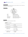
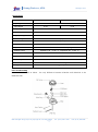
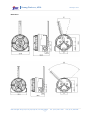
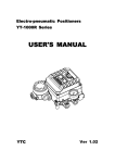
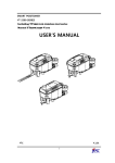
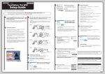
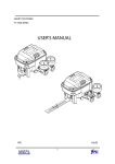
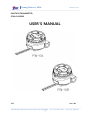
Young Tech co, LTD. www.ytc.co.kr POSITION TRANSMITTER PTM-6V SERIES USER'S MANUAL YTC Ver 1.00 #662-8 PungMu Dong, Kimpo City, KyeongGi Do, 415-809, KOREA 1 TEL: (82 31) 986 – 8545 FAX: (82 31) 986-2683 Young Tech co, LTD. www.ytc.co.kr Table of Contents Contents Page No. Introduction 3 Manufacturer Warranty 3 Product Description 4 Label Description 4 Suffix Symbol 4 Specification 5 Parts and Assembly 5 Dimension 6 Operation Logic 7 Installation 7 PTM-6VL 7 PTM-6VR 9 Connection – Power 10 Adjustment – RA / DA 11 Adjustment – Zero and Span 11 Adjustment – Potentiometer 12 Troubleshooting 13 #662-8 PungMu Dong, Kimpo City, KyeongGi Do, 415-809, KOREA 2 TEL: (82 31) 986 – 8545 FAX: (82 31) 986-2683 Young Tech co, LTD. www.ytc.co.kr Introduction Thank you for choosing YTC product. Each product is fully inspected after the production to offer you the highest quality. In order to fully utilize the product, we strongly recommend users to read the manual carefully and fully understood. The manual should be provided to the end-user. The manual can be altered or revised without any prior notice. Any changes in product's specification, structure, and/or any components may not result immediate revised version of the manual. The manual should not be duplicated or reproduced for any purpose without any approval from Young Tech Co., Ltd, South Korea. Manufacturer Warranty For the safety, it is imperative to follow instructions in the manual. It is not manufacturer's liability for any damages which caused by users' negligence. It is not manufacturer's liability for any damages or accidents which resulted by any alteration or modification of the product and parts. If alteration or modification is necessary, please contact the manufacturer directly. Manufacturer warrants the product from the date of original retail purchase of the product for one (1) year, except as otherwise stated. Manufacturer warranty will not cover the products that the product have been subjected to abuse, accident, alteration, modification, tampering, negligence, misuse, faulty installation, lack of reasonable care, repair or service in any way that is not contemplated in the documentation for the product, or if the model or serial number has been altered, tampered with, defaced or removed; damages that occurs in shipment, due to act of God, failure due to power surge, and cosmetic damage. Improper or incorrectly performed maintenance or report voids this Limited Warranty. For detailed warranty information, please contact the corresponding local Young Tech Co., Ltd office or main office in South Korea. Safety Precautions PTM-6V is designed for explosion proof area. The user must follow other explosion proof procedures and safety precautions. PTM-6V must be used under explosion proof certified environment. 20’C ~ 60’C. Temperature range is - If PTM-6V is used under non-explosion proof environment, it can be used under temperature range of -30’C ~ 85’C. #662-8 PungMu Dong, Kimpo City, KyeongGi Do, 415-809, KOREA 3 TEL: (82 31) 986 – 8545 FAX: (82 31) 986-2683 Young Tech co, LTD. www.ytc.co.kr Product Description PTM-6V series mechanically changes the position of the stem installed on the valve or similar device and transmits DC 4~20mA of electric signal. Label Description Model: Indicates model number. Input: Indicates input angle range. Output: Indicates output current signal. Explosion Proof: Indicates explosion proof grade. Ambient Temp: Indicates operate ambient temperature. Serial Number: Indicates unique serial number. Suffix Symbol PTM-5V series follows suffix symbols as follows. #662-8 PungMu Dong, Kimpo City, KyeongGi Do, 415-809, KOREA 4 TEL: (82 31) 986 – 8545 FAX: (82 31) 986-2683 Young Tech co, LTD. www.ytc.co.kr Specification Item/Model PTM-6VL PTM-6VR Input Type Input Signal 2Wire 0~30 ゚ 0~90 ゚ Output Signal 4~20mA Max.600 Ω / 28V DC Load Resistance Supply Voltage 9~28V DC Noise Range 50mV p.p Conduit PF 1/2 (G 1/2) Protection IP67 Explosion Proof Ex ia llC T6 <certification is under progress> Ambient Temp Operating:-30 ゚ C~85 ゚ C, Explosion:-20 ゚ C~60 ゚ C Linearity ± 1% F.S. Hysteresis 0.5% F.S. Sensitivity ± 0.2% F.S. Material Aluminum Casting Weight 0.6Kg(1.3lb) Parts and Assembly PTM-5VL is assembled as below. The only difference between PTM-5VL and PTM-5VR is the feedback lever. #662-8 PungMu Dong, Kimpo City, KyeongGi Do, 415-809, KOREA 5 TEL: (82 31) 986 – 8545 FAX: (82 31) 986-2683 Young Tech co, LTD. www.ytc.co.kr Dimension #662-8 PungMu Dong, Kimpo City, KyeongGi Do, 415-809, KOREA 6 TEL: (82 31) 986 – 8545 FAX: (82 31) 986-2683 Young Tech co, LTD. www.ytc.co.kr Operation Logic Feedback lever main shaft rotates as position changes of valve stem transmits to Position Transmitter’s feedback lever. shaft and resistance gear. The rotation angle information sent to potentiometer through the main Resistance change in the potentiometer transforms into the electric current and sent to the control center. Position changes of valve stem (0~100%) sends different electric signal (4~20mA) respectively to the control center. Installation Safety Warning When installing the product, please make sure to read and follow safety instruction. Always wear safety equipments and follow safety procedures. Please shut down valve and actuator temporarily. In order to prevent shut down of total system, please utilize by-pass valve or similar and dissemble the valve which position transmitter will be installed. In explosive area, please make sure no explosive gas present at the installing area. PTM-6VL Installation PTM-6VL should be used in linear operating actuators that are spring return type diaphragm actuator, piston actuator with globe valve, or gate valve. ① Please refer to actuator and position transmitter dimensions to make proper bracket. Please consider following when making a bracket. A. Feedback lever should be leveled at 50% of valve stroke. B. Feedback lever connection bar of actuator clamp should be installed at the position that the valve stroke and numbers which indicated on the feedback lever must be fitted. <Figure 1> ② Attach PTM-6VL to the bracket, which was made in earlier step, by using bolts. <Fig 2>. Please refer to the backside of the product for size of the bolts. The standard size of bolt is M8 x 1.25P, and other bolt sizes are available. Please contact YTC sales department. #662-8 PungMu Dong, Kimpo City, KyeongGi Do, 415-809, KOREA 7 TEL: (82 31) 986 – 8545 FAX: (82 31) 986-2683 Young Tech co, LTD. www.ytc.co.kr <Fig 2> <Fig 3> ③ Attach PTM-6VL (with bracket) to the actuator yoke – DO NOT TIGHTEN COMPLETELY. ④ Connect PTM-6VL feedback lever to the actuator clamp. The gap on the feedback lever is 6.5mm. The connection bar thickness should be less than 6.3mm. <Fig 3>. ⑤ Connect air filter regulator to the actuator temporarily. Set supply pressure of the regulator in order to position the actuator clamp at 50% of valve stroke. <Fig 4> ⑥ Insert connection bar into PTM-6VL feedback lever. The connection bar should be inserted at the 50% point on the feedback lever, which would help to reduce hysteresis. <Fig 4> <Fig 4> ⑦ Check the valve stroke. The stroke numbers are indicated on the feedback lever. Position connection bar at the number on the feedback lever according to the valve stroke. <Fig 7> To adjust, move the bracket or the connection bar. Note After installing PTM-6VL, operate the valve from 0% to 100% stroke by using air filter regulator on the actuator. Both at 0% and 100%, the feedback lever should no touch the lever stopper, which is located on the backside of PTM-6VL. <Fig 5>. If the feedback lever touches the lever stopper, PTM-6VL should be installed further away from the center of the yoke. ⑧ After the proper installation, tighten all of the bolts on the bracket, the feedback lever, and the connection bar. #662-8 PungMu Dong, Kimpo City, KyeongGi Do, 415-809, KOREA 8 TEL: (82 31) 986 – 8545 FAX: (82 31) 986-2683 Young Tech co, LTD. www.ytc.co.kr PTM-6VR Installation PTM-6VR should be used for rotary motion valve, that is ball valve, butterfly valve using rack and pinion, scotch yoke or complex type actuator, which its stem rotates 90 degrees. ① Before installing PTM-6VR, please set the actuator as default position. For single acting type (spring return type), the actuator will automatically default itself when the air pressure shuts down. For double acting type (non-spring return type), the default position must be set manually according to the actuator’s specification. ② Please refer to the actuator and the position transmitter dimensions to make appropriate bracket. PTM-6VR offers two types of lever – standard and NAMUR Please see <Figure 6> to make and install with appropriate bracket. <Fig 6> ③ After appropriate bracket is produced, please install the assembled PTM-6VR on the actuator, and fasten screws completely. <Figure 6> #662-8 PungMu Dong, Kimpo City, KyeongGi Do, 415-809, KOREA 9 TEL: (82 31) 986 – 8545 FAX: (82 31) 986-2683 Young Tech co, LTD. www.ytc.co.kr Connection - Power Note Before connecting terminal, please make sure that power is off completely. PTM-6V must be grounded. Please use twisted cable with conductor section area 1.25 ㎟ and that is suitable for 600V (complying to the conductor table of NEC Article 310.) The outer diameter of the cable should be between 6.35~10mm. Use shield wire to protect against electro-magnetic field and noise. Please do not install PTM-6V the cable near the equipments such as high-capacity transformer or motor which creates noise. #662-8 PungMu Dong, Kimpo City, KyeongGi Do, 415-809, KOREA 10 TEL: (82 31) 986 – 8545 FAX: (82 31) 986-2683 Young Tech co, LTD. www.ytc.co.kr Adjustment Adjustment – RA/DA PTM-6V is set as DA control as a default. Depends on valve operation (DA/RA), insert appropriate connector to the socket. <Fig 8> Adjustment – Zero and Span Please operate valve manually while checking output current valve from PTM-6V. 0% of valve stroke and rotation angel need 4mA and 100% for 20mA. If current signal does not match, please follow below direction to set zero and span. <Fig 9> ① Set the stroke or rotation angle as 0%, and check if output signal is 4mA. If output signal is greater than 4mA, then rotate zero adjuster counter-clockwise. If output signal is less than 4mA, then rotate the adjuster clockwise to set it to 4mA. ② Set the stroke or rotation angle as 100%, and check if output signal is 20mA. If output signal is greater than 20mA, then rotate zero adjuster counter-clockwise. If output signal is less than 20mA, then rotate zero adjuster clockwise to set it to 20mA. ③ Zero and span setting is critical, so please repeat step ① and ② 2~3 times to retrieve accurate setting. <Fig 9> #662-8 PungMu Dong, Kimpo City, KyeongGi Do, 415-809, KOREA 11 TEL: (82 31) 986 – 8545 FAX: (82 31) 986-2683 Young Tech co, LTD. www.ytc.co.kr Adjustment – Potentiometer Potentiometer is designed to output 12mA signal when the feedback lever is at 50% position. In case of dislocation of the potentiometer, please follow below procedure to re-set the potentiometer. <Fig 10 & 11> Power must be turned off before adjusting potentiometer. Please be cautious when adjusting potentiometer. Please make sure that there is no remaining circuit on the PCB. Please do not use excessive force when disconnecting potentiometer from the PCB. 1. 2. 3. Locate the potentiometer under the PCB. Disconnect from the PCB. Please do not use excessive force. Unfasten lock screw which locks the potentiometer gear and take out potentiometer body from the lag-gear. Fix the feedback lever at 50% position and measure resistance level by connecting two probes out of three inlets. 4. Rotate pinion gear until resistance vale is about 5KΩ. 5. After setting the resistance value, rotate stopper to the normal position and fasten the lock screw. 6. Reconnect potentiometer to the PCB and reinstall PCB onto PTM-6V body. <Fig 10> <Fig 11> #662-8 PungMu Dong, Kimpo City, KyeongGi Do, 415-809, KOREA 12 TEL: (82 31) 986 – 8545 FAX: (82 31) 986-2683 Young Tech co, LTD. www.ytc.co.kr Troubleshooting 1. PTM-6V shows no output signal. A. Check actual input signal to PTM-6V. B. Check power connection and + / - poles. 2. Input signal value to positioner and output signal value from PTM-6V differs dramatically. A. Check input signal value and supply voltage. Insufficient voltage can affect input signal value. B. Check the installation of positioner. If positioner is installed improperly, please refer to positioner’s manual and re-install the positioner. C. Set positioner’s zero and span again. Inaccurate zero and span setting can lower accuracy and linearity. D. Check the installation of position transmitter, PTM-6V. If PTM-6V is installed improperly, then refer to the manual and re-install. E. Set PTM-6V zero and span again. 3. Sudden change in PTM-6V’s output signal value. A. Please make sure that PTM-6V’s lever is placed at the 50% point. It not, PTM-6V needs to be re-installed and adjusted to place at the 50% point. B. Adjust potentiometer. Potentiometer’s load resistance is 10KΩ, and it should be read at the 50% point. #662-8 PungMu Dong, Kimpo City, KyeongGi Do, 415-809, KOREA 13 TEL: (82 31) 986 – 8545 FAX: (82 31) 986-2683 Young Tech co, LTD. www.ytc.co.kr Young Tech Co., Ltd. Address: 662-8, Pungmu-Dong, Kimpo-City, Kyeonggi-Do, Korea Phone: 82-31-986-8545 Fax: 82-31-986-2683 Web: www.ytc.co.kr This manual can be changed or revised without any prior notice. For latest version, please contact YTC website. Issued: 2009.APR,13 Version 1.00 #662-8 PungMu Dong, Kimpo City, KyeongGi Do, 415-809, KOREA 14 TEL: (82 31) 986 – 8545 FAX: (82 31) 986-2683