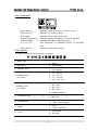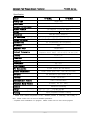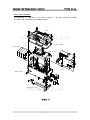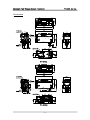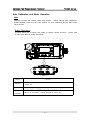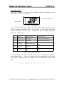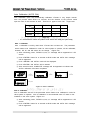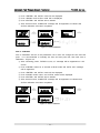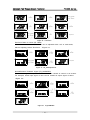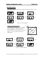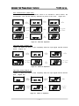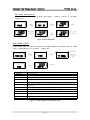
1
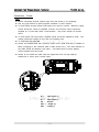
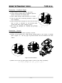
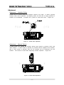
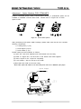
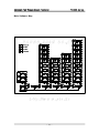
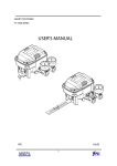
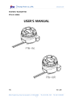
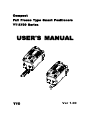
Compact Fail Freeze Type Smart Positioners YT-2700 Series USER'S MANUAL YTC Ver 1.00 Compact Fail-Freeze Smart Positioner YT-2700 Series Table of Contents Introduction 3 Manufacturer Warranty 3 Product Description 4 Main Features and Functions 4 Label Description 5 Suffix Symbol 5 Specification 6 Parts and Assembly 7 Dimensions 8 Installation 9 YT-2700L 9 YT-2700R 13 Connection 16 Connection - Piping 16 Connection - Power 17 Connection - Feedback Singal 18 Connection - Ground 18 Adjustment 19 Adjustment - Variable Orifice 19 Adjustment - Manual Switch 19 Adjustment - Option Modules PCB (PTM / HART) 20 Auto Calibration and Basic Operation 21 Button Description 21 Run Mode (RUN) 22 Auto Calibration (AUTO CAL) 23 Auto 1 Calibration 23 Auto 2 Calibration 23 - 1 - Compact Fail-Freeze Smart Positioner Auto 3 Calibration YT-2700 Series 24 Manual Mode (MANUAL) 25 Parameter Mode (PARAM) 25 Dead-Zone (dEAdZONE) 26 P-Value (KP1) 26 D1-Value (Kd1) 26 P2-Value (KP2) 27 D2-Value (Kd2) 27 PT-Value (PT1) 27 PT-Value (PT2) 27 KP_ and D_ Value 27 Hand Calibration Mode (HANd CAL) 28 Zero-Point (PZ_ZERO) and End-Piint (PZ_END) for Valves 28 Zero-Point (TR_ZERO) and End-Point (TR_END) for Transmitter 28 End-Point Ratio for Valves (PE_TRIM) 29 Normal / Reverse Feedback Signal (TR_NORM / REV) 29 Valve Mode (VALVE) 30 Acting Adjustment (ACT) 30 Characteristic Adjustment (CHAR) 30 User Characteristic (USER SET) 31 Tight Shut Open (TSHUT OP) 31 Tight Shut Close (TSHUT CL) 31 Split Range Control (SPLIT) 32 View Mode (VIEW) 32 Error and Warning Code 33 Main Software Map 34 - 2 - Compact Fail-Freeze Smart Positioner YT-2700 Series Introduction Thank you for choosing YTC product. Each product is fully inspected after the production to offer you the highest quality. In order to fully utilize the product, we strongly recommend users to read the manual carefully and fully understood. z The manual should be provided to the end-user. z The manual can be altered or revised without any prior notice. Any changes in product's specification, structure, and/or any components may not result immediate revised version of the manual. z The manual should not be duplicated or reproduced for any purpose without any approval from Young Tech Co., Ltd, South Korea. Manufacturer Warranty - For the safety, it is imperative to follow instructions in the manual. It is not manufacturer's liability for any damages which caused by users' negligences. - It is not manufacturer's liability for any damages or accidents which resulted by any alteration or modification of the product and parts. If alteration or modification is necessary, please contact the manufacturer directly. - Manufacturer warrants the product from the date of original retail purchase of the product for one (1) year, except as otherwise stated. - Manufacturer warranty will not cover the products that the product have been subjected to abuse, accident, alteration, modification, tampering, negligence, misuse, faulty installation, lack of reasonable care, repair or service in any way that is not contemplated in the documentation for the product, or if the model or serial number has been altered, tampered with, defaced or removed; damages that occurs in shipment, due to act of God, failure due to power surge, and cosmetic damage. Improper or incorrectly performed maintenance or report voids this Limited Warranty. - For detailed warranty information, please contact the corresponding local Young Tech Co., Ltd office or main office in South Korea. - 3 - Compact Fail-Freeze Smart Positioner YT-2700 Series Product Description YT-2700 Smart Vavle Positioner accurately controls valve stroke, according to input signal of 4-20mA which is being input from the controller or control room. In addition, built-in micro-processing operator optimizes the positioner's performance and provides unique functions such as Auto calibration, PID control, Alarm, and Hart protocol. Main Features and Functions 1. YT-2700 series stays at the last positioner when the input signal and/or supply pressure fails without any additional accessories such as lock-up valve or solenoid valve. 2. LCD display enables users to monitor the status of the positioner. 3. The positioner operates normally even there is a sudden change in supply pressure and high vibration environment. 4. The method of Auto Calibration is very simple. 5. Due to the small size of the positioner, it can be installed on a small actuator. 6. Very low air consumption level and low voltage use (8.5V) yields lower operating cost, and it is compatible with most of the controllers. 7. Variable orifice can minimize the hunting occurrence and optimize operating condition. 8. Various sets of information can be interchanged by HART communication between a valve and a positioner. 9. Valve system becomes more stable by outputting analog feedback signal. 10. Tight Shut-Close and Shut-Open can be set. 11. PID parameters can be adjusted in the filed without any additional communicator. 12. A/M Switch can change the flow of the pressure, whether to send directly to actuator. 13. Split range 4-12mA or 12-20mA can be set. 14. Hand Calibration function can set Zero and Span values. 15. It has IP66 protection grade. 16. Air filter regulator can be attached with only one linear nipple. It does not require extra piping. 17. Epoxy polyester power coating resists against the corrosion process. 18. Maintenance of the positioner is easy because of modularized inner structure. 19. Size is very compact. - 4 - Compact Fail-Freeze Smart Positioner YT-2700 Series Label Description Model Number: Indicates model name and any option (if any). Explosion Proof: Indicates the protection grade. Input Signal: Indicates current input signal range. Ambient Temperature: Indicates ambient temperature for normal operation. Supply Pressure: Indicates the range of supply pressure. Ui, Ii, Pi, Ci, Li: See certificates for parameter values of intrinsically safe. Serial Number: Indicates unique serial number. Suffix Symbol YT-2700 series follows suffix symbols as follows. YT-2700 S Motion type Acting type Explosion proof L : Linear R : Rotary S : Single acting I : Ex ia IIC T6/T5 <in progress> n : non-explosion 1 : 10 ~ 40 mm Feedback lever 2 : 20 ~ 70 mm (YT-2700L) 3 : 50 ~ 100 mm 4 : 100 ~ 150 mm 1 : M6 x 40L Feedback lever (YT-2700R) 2 : M6 x 63L 3 : M8 x 40L 4 : M8 x 63L 5 : NAMUR Standard Connection type Communication Option Option 1 1 : PT 1/4 2 : NPT 1/4 0 : None 2 : HART communication 0 : None 1 : Position transmitter F : Fail Freeze S : Fail Safe - 5 - Compact Fail-Freeze Smart Positioner YT-2700 Series Specification Model YT-2700L YT-2700R Acting Type Single Only Input Signal 4~20mA DC Minimum Current Signal Supply Pressure Stroke 3.2mA(Standard), 3.8mA(Hart Included) 2 1.4~7kgf/cm ( 0.14~0.7 MPa ) 10~150 mm Impedance 45~90° Max.460 Ohm/ 20mA DC Air Connection PT 1/4, NPT 1/4 Gauge Connection PT 1/8, NPT 1/8 Conduit Entry PF 1/2(Standard), NPT1/2(Option) Protection IP66 Explosion Proof Ambient Temperature ExiaIICT6/T5 Operating Temp:-30~85℃ Explosion Proof Temp: -30~60℃(T5)/-30~40℃(T6) Linearity ±0.5% F.S. Hysteresis 0.5% F.S. Sensitivity ±0.2% F.S Repeatability 0.3% F.S. Flow Capacity 70 LPM Air Consumption Output Characteristic 0 LPM (sup=1.4K, idle status) Linear, Quick Open, EQ%, User Set (16 Point) Vibration No Resonance upto 100Hz at 6G Humidity 5-95% RH at 40℃ Communication (Option) HART Communication Feedback Signal (Option) 4-20mA ( DC 10 - 30V ) Material Aluminum Diecasting Weight 1.5 kg (3.3 lb) Painting Epoxy Polyestere Powder Coating * Tested under ambient temperature of 20℃, absolute pressure of 760mmHg, and humidity of 65%. Please contact YTC for the more detailed specification. * Explosion Proof certification is in progress. Please contact YTC for most current progress. - 6 - Compact Fail-Freeze Smart Positioner YT-2700 Series Parts and Assembly The structure of YT-2700L is as shown <Figure1>. The only difference between YT-2700L and YT-2700R is the feedback lever. Cover Cover Sealing Pilot Relay PCB Cover PCB Main Body Feedback Lever <Figure 1> - 7 - Compact Fail-Freeze Smart Positioner Dimensions YT-2700L YT-2700R - 8 - YT-2700 Series Compact Fail-Freeze Smart Positioner YT-2700 Series Installation Safety Warning When installing a positioner, please ensure to read and follow safety instruction. z All input and supply pressure to valve, actuator, and other related devices must be turned off. z Use bypass valve or other equipment to avoid entire system "shut down." z Make sure there is no remaining pressure in the actuator. Tools for Installation ① Hexagonal wrench ② Screw drivers (+) & (-) ③ Spanners for hexagonal-head bolts YT-2700L Installation YT-2700L should be installed on linear motion valve such as globe valve or gate valve using spring return type of diaphragm or piston actuator. Before installation, be sure to check for following installation components. ① YT-2700 main body ② Feedback lever and lever spring ③ Flange nut (bottom side of YT-2700L) ④ 4 pcs of hexagon head bolts (M8 x 1.25P) ⑤ 4 pcs of M8 plate washer Installation Steps YT-2700L installation example (1) Proper bracket must be made in order to attach positioner on the actuator yoke. Please consider following when making a bracket. ① Feedback lever should be leveled at 50% of valve stroke. (Refer to Step 7) ② Feedback lever connection bar of actuator clamp should be installed at the positioner that the valve stroke and numbers which indicated on the feedback lever must be fitted. (Refer to Step 8) - 9 - Compact Fail-Freeze Smart Positioner YT-2700 Series (2) Attach YT-2700L to the bracket, which was made in earlier step, by using bolts. <Figure 2> Please refer to backside of the product for size of the bolts. standard size of bolt is M8 X 1.25P, and other bolt sizes are available. The Please contact YTC sales department. <Figure 2: Installing YT-2700L with bracket> (3) Attach YT-2700L (with bracket) to the actuator yoke - DO NOT TIGHTEN COMPLETELY. (4) Connect YT-2700L feedback lever to the actuator clamp. The gap on the YT-2700L feedback lever is 6.5mm. The connection bar thickness should be less than 6.3mm. <Figure 3> <Figure 3> - 10 - Compact Fail-Freeze Smart Positioner YT-2700 Series (5) Connect air filter regulator to the actuator temporarily. Set supply pressure of the regulator in order to position the actuator clamp at 50% of valve stroke. <Figure 4> <Figure 4> <Figure 5> (6) Insert connection bar into the YT-2700L feedback lever. The connection bar should be inserted at the 50% point on the feedback lever, which would help to reduce hysteresis. <Figure 5> (7) If connection bar does not point at 50% point, then adjust bracket or feedback link bar position. Failure to position at 50% would lower the linearity of the positioner. <Figure 6> <Figure 6> - 11 - Compact Fail-Freeze Smart Positioner (8) Check valve stroke. YT-2700 Series The stroke numbers are indicated on the feedback lever. Position connection bar at the number on the feedback lever according to the valve stroke. <Figure 7> To adjust, move the bracket or the connection bar. Stroke 70mm Stroke 30mm <Figure 7> Note After installing YT-2700L, operate the valve from 0% to 100% stroke by using air filter regulator on the actuator. Both of 0% and 100%, the feedback lever should not touch the lever stopper, which is located on the backside of YT-2700L. <Figure 8> If the feedback lever touches the lever stopper, YT-2700L should be installed further away from the center of the yoke. <Figure 8> (9) After the proper installation, tighten all of the bolts on the bracket, the feedback lever, and the connection bar. - 12 - Compact Fail-Freeze Smart Positioner YT-2700 Series YT-2700R Installation YT-2700R should be used for rotary motion valve, that is ball valve, butterfly valve using rack and pinion, scotch yoke or complex type actuator, which its stem rotates 90 degrees. Before installation, be sure to check for following installation components. ① YT-2700R main body ② Fork lever and lever spring ③ 1 set of bracket ④ 4 pcs of hexagon head bolts (M8 x 1.25P) ⑤ 4 pcs of M8 plate washer YT-2700R Installation Example YT-2700R on Fork Lever YT-2700R on NAMUR Lever Bracket Information YT-2700R is supplied with standard bracket. The bracket can be used for Fork lever and NAMUR bracket. Please see <Figure 9, 10, & 11> for more detailed information. Actuator stem height (H) 20mm 30mm 50mm A-L H : 20 H : 30 H : 50 Markings of bolt holes B-L A-R H : 20, 30 H : 20 H : 20, 30 H : 30 H : 50 H : 50 B-R H : 20, 30 H : 20, 30 H : 50 <Figure 9> 1. Standard actuator stem height (H) is 20, 30, or 50mm. After checking "H", assemble with the bracket as shown in <Figure 9, 10, & 11> Actuator Stem (H) Actuator <Figure 10> - 13 - Compact Fail-Freeze Smart Positioner YT-2700 Series <Figure 11> 2. Attach bracketed YT-2700R to the actuator by using hexagon-headed and wrench bolts. Size of the bracket hole is 6mm. When tightening bolts, use spring washer or similar for firm attachment to the actuator, so YT-2700R will not shake by vibration or any other impact. The direction of bracket is different by the operating condition, but normally, the positioner is installed as shown in <Figure 12>. 3. Set rotation position of the actuator stem at zero point, "0%". For a single type of actuator, it is easy to check zero point, because the actuator stem is positioned at zero point when there is no supply pressure. If double acting actuator is used, check actuator stem's rotation direction (clockwise or counter-clockwise) by supplying pressure. 4. Install the fork lever as shown in <Figure 13> after setting actuator stem at zero point. Check the direction of the actuator stem - clockwise or counter-clockwise. Installation angle of the fork lever should be 45 degrees based on the linear shaft. For NAMUR shaft, the angle does not matter. counter-clockwise clockwise <Figure 13> - 14 - Compact Fail-Freeze Smart Positioner YT-2700 Series 5. After setting fork lever position, lock nuts which are assembled on the bottom of the fork lever. Make sure to set upper height of the fork lever between 6-11mm, which is lower than upper bracket height. 6. Attach YT-2700R to the bracket. Fix the clamping pin on the main shaft's center of YT-2700R and insert connection bar into the fork lever slot, so it can be locked to the fork lever spring. This sets the alignment of the main shaft of YT-2700R and center of the actuator stem. Bad alignment of the main shaft and the actuator stem lowers YT-2700R's durability, because too much force will be on the main shaft of YT-2700R. <Figure 14> Fork Lever Clamping Pin Connection Bar Main Shaft <Figure 14> 7. Tighten YT-2700R base and the bracket with hexagon-headed bolts and plate washer. It is recommended to tighten four bolts after checking YT-2700R's position. <Figure 16> - 15 - Compact Fail-Freeze Smart Positioner YT-2700 Series Connection Connection - Piping Note z To avoid entering moisture, oil, or dust into the product, please carefully make selection of supply pressure compressor. z It is recommended to attach air filter regulator before supply port of YT-2700R. Supply Pressure Condition ① Dry air with at least 10℃ lower than ambient temperature. ② Avoid from dusty air. Filter can only sort 5 micron or larger. ③ Avoid any oil. ④ Comply with ANSI/ISA-57.3 1975(R1981) or ISA S7.3-1975(R1981). ⑤ Not to be used beyond the range of 1.4 - 7 kgf/㎠(140 - 700 kPA). ⑥ Set air filter regulator's supplied pressure 10% higher than actuator's spring range pressure. Pipe Connection ① Make sure inside of pipe is emptied. ② Do not use pipeline that is squeezed or has hole. ③ To maintain flow rate, use the pipeline that has more than 6mm inner diameter. (10mm outer diameter) ④ Do not use extremely long pipeline system. It may affect flow rate due to the friction inside of the pipeline. Piping Connection with Actuator YT-2700 series single acting type is set to use OUT1 port. OUT1 port should be connected with supply pressure port from actuator when using single acting type of spring return actuator. <Figure 15 & 16> <Figure 15: YT-2700L> <Figure 16: YT-2700R> - 16 - Compact Fail-Freeze Smart Positioner YT-2700 Series Connection - Power Note z Before connecting terminal, please make sure that power is off completely. z Use ring type terminal to protect against oscillation or other impacts. z YT-2700 series (except internal PTM type) must use DC 4-20mA. Minimum supply current should be 3.2mA for standard YT-2700, and minimum 3.8mA should be supplied for YT-2700 with HART communication. The power should not exceed 24mA. z YT-2700 series with PTM option, separate power should be supplied to PTM. The voltage should be between 9~27V and not exceeding 30V. z YT-2700 must be grounded. z Please use twisted cable with conductor section area 1.25㎟ and that is suitable for 600V (complying to the conductor table of NEC Article 310.) The outer diameter of the cable should be between 6.35~10mm. Use shield wire to protect against electro-magnetic field and noise. z Please do not install the cable near the equipments such as high-capacity transformer or motor which creates noise. IN + : Input signal (+) IN - : Input signal (-) FG : Ground OUT + : Output (+) OUT - : Output (-) - 17 - Compact Fail-Freeze Smart Positioner YT-2700 Series Connection - Feedback Signal 1) Open product cover by opening 4 M4 bolts. 2) Loose terminal locking bolts of feedback signal for position transmitter on terminal plate. 3) Insert cables through cable connector in YT-2700. 4) Use ring type when connecting terminals in order to lock completely. 5) Insert terminal bolts through the holes and lock them with (+) and (-) terminals on the terminal plate. Tighten bolts with 1.5Nm (15kfgcm) torque. 6) Be sure the polarities of terminals are properly connected. Connection - Ground 1) Ground must be done before operating YT-2700. 2) Inside of the terminal box, locate ground terminal plate at the center of terminal plate. <Figure 17> Use any type of ground terminal with the resistance less than 100hm. <Figure 22: Ground Terminal> 3) Make sure to use ring type ground cable in order to lock them completely. - 18 - Compact Fail-Freeze Smart Positioner YT-2700 Series Adjustment Adjustment - Variable Orifice Hunting can be occurred when the actuator's volume is too small. hunting, orifice can be adjusted. In order to prevent By adjusting orifice, the flow rate of supply pressure to actuator can be adjusted. To adjust, use (-) driver to control the orifice. <Figure 23> <Figure 23: Variable Orifice Adjustment> Adjustment - Manual Switch YT-2700 series can operate the actuator without input signal by pressing "SUP" and "EXT" buttons. If "SUP" button is pressed, air pressure will be supplied to the actuator, and if "EXT" button is pressed, then the air pressure will be exhausted from the actuator. This function is used when diagnosing actuator operation. <Figure 24> <Figure 24: Manual Switch Adjustment> - 19 - Compact Fail-Freeze Smart Positioner YT-2700 Series Adjustment - Option Modules PCB (PTM/HART) Position Transmitter (PTM), HART Communication (HART), or PTM+HART option can be installed on standard YT-2700 series PCB. Please refer to <Figure 25> for each option's PCB. <Figure 25: PCB for Each Options> After purchasing PCB Option Adder Package, please make sure that the box contains following components. ① Locking bolts (1 pcs) ② PCB support (2 pcs) ③ PCB module (1 pc) Please install the PCB modules as follows. (1) Open the cover and separate main PCB board from the body. (2) Refer to <Figure 26>, and lock bolt on the bottom with PCB supports. (3) Insert 14-pins to the 14-pins lot completely. (4) Lock another 1 bolt on the top of the PCB. (5) Re-install main PCB on the main body. * When HART option PCB installed on the main PCB, please make sure to REMOVE option jumper Option Jumper <Figure 26> - 20 - Compact Fail-Freeze Smart Positioner YT-2700 Series Auto Calibration and Basic Operation Note Following process will operate valve and actuator. Before starting Auto Calibration, please separate valve from the entire system, so Auto Calibration will not affect entire valve process. Button Description YT-2700 series has 4 buttons and enable to perform various functions. Please refer to the below table for further description Button <ENTER> <ESC> <UP> & <DOWN> Function Enter to main menu and sub-menus, save adjusted parameter values, etc. Return to previous menu. Move to next menu, change parameter values, etc. - 21 - Compact Fail-Freeze Smart Positioner YT-2700 Series Run Mode (RUN) After power connection to YT-2700 series, following message will appear on LCD screen within 6 seconds. <Figure 27> ⇦ Process Value (PV) Run mode ⇨ <Figure 27: LCD Message> "RUN" indicates that YT-2700 adjusts valve stroke with receiving signals (4~20mA) and "PV" indicates the process value. In RUN mode, the valve stroke continuously changes according to the input signal. There are six types of display message in RUN mode. <Figure 28> ① Run PV Process Value Valve Stroke (%) ② Run SV % Set Value Input Signal (0∼100%) ③ Run SV mA Set Value Input Signal (4∼20mA) ④ Run MV Manipulate Value ⑤ Run Vel Velocity ⑥ Run Err Error Motor Manipulate Value (Digit) Current Valve Stem's Velocity (Digit) Difference between SV and PV (%) <Figure 28: Type of display message> To change display, push <ESC> and <UP> at same time. order indicated above. The display will change in If <ESC> and <DOWN> pushed simultaneously, the order will be displayed in opposite order. By pressing <ESC>, the display will return to RUN Mode. - 22 - Compact Fail-Freeze Smart Positioner YT-2700 Series Auto Calibration (AUTO CAL) Auto Calibration (Auto Cal) automatically calibrates YT-2300 in very simple manner. Auto Cal process takes about 2~3 minutes, and the duration of the process varies upon the size of the actuator as well. There are 3 types of Auto Cal. <Figure 29> Zero Point End Point KP, KI, KD RA / DA AUTO1 ○ ○ × x AUTO2 ○ ○ ○ ○ AUTO3 × × ○ ○ <Figure 29> * It is recommended to calibrate the positioner under AUTO2 when setting the system initially. Auto 1 Calibration Auto 1 Calibration is mainly used when YT-2700 has not been set. The parameter which needs to be calibrated in order for valve system to operate, will be calibrated; however, KP, KI, and KD values do not change. <Figure 30> ① After connecting power, "READY 6,5,4,3,2,1" message will be appeared on LCD screen. ② Push <ENTER> button for 6 seconds at RUN mode and AUTO CAL message will be appeared. ③ Push <ENTER> and AUTO1 mode will be displayed. ④ Push <ENTER> and AUTO1 will be started. ⑤ After several minute, COMPLETE message will be appeared to indicate that AUTO1 calibration has been completed. ⇨ <ENTER> 6 seconds ⇨ <ENTER> ⇨ <ENTER> Completed <Figure 30: AUTO1 Calibration> Auto 2 Calibration Auto 2 Calibration sets all of the parameter which needs to be calibrated in order for valve system to operate. Auto 2 Calibration is recommended when YT-2700 is first installed on the valve system. <Figure 31> ① After connecting power, "READY 6,5,4,3,2,1" message will be appeared on LCD screen. ② Push <ENTER> button for 6 seconds at RUN mode and AUTO CAL message will be appeared. - 23 - Compact Fail-Freeze Smart Positioner YT-2700 Series ③ Push <ENTER> and AUTO1 mode will be displayed. ④ Push <DOWN> and AUTO2 mode will be displayed. ⑤ Push <ENTER> and AUTO2 will be started. ⑥ After several minute, COMPLETE message will be appeared to indicate that AUTO2 calibration has been completed. ⇨ <ENTER> 6 seconds ⇨ <ENTER> ⇨ <ENTER> Completed ⇨ <DOWN> <Figure 31: AUTO2 Calibration> Auto 3 Calibration Auto 3 Calibration sets all of the parameters, but it does not change the zero and end point. It is recommended to manually set zero and end point first, then start Auto 3 Calibration. <Figure 33> ① After connecting power, "READY 6,5,4,3,2,1" message will be appeared on LCD screen. ② Push <ENTER> button for 6 seconds at RUN mode and AUTO CAL message will be appeared. ③ Push <ENTER> and AUTO1 mode will be displayed. ④ Push <DOWN> button twice, and AUTO3 mode will be displayed. ⑤ Push <ENTER> and AUTO3 will be started. ⑥ After several minute, COMPLETE message will be appeared to indicated that AUTO3 calibration has been completed. ⇨ <ENTER> 6 seconds ⇨ <ENTER> ⇨ <ENTER> Complete <Figure 33: AUTO3 Calibration> - 24 - ⇨ <DOWN> 2 times Compact Fail-Freeze Smart Positioner YT-2700 Series Manual Mode (MANUAL) MANUAL MODE is used to move valve stem manually. YT-2700 moves valve strokes, not by input signal. During MANUAL MODE, The movement of the stroke does not affect YT-2700 saved data values, and it just moves valve strokes up/down physically. <Figure 34> ⇨ <ENTER> 6 seconds ⇨ <UP>/<DOWN> ⇨ <DOWN> ⇨ <ENTER> ⇨ <ESC> Completed <Figure 34: MANUAL MODE> Tip when increasing/decreasing value <UP> only Increase stem value slowly <UP> + <ENTER> Increase stem value quickly <DOWN> only Decrease stem value slowly <DOWN> + <ENTER> Decrease stem value quickly Parameter Mode (PARAM) AUTO CAL optimizes most of the valve actuator controls. However, in some instances, there can be exceptions. Usually hunting or oscillation occurs when the valve actuator controls did not optimize. When this occurs, hunting or oscillation can be prevented by adjusting parameter values and DeadZone. 4 Types of Parameter and Adjustment ① Dead-Zone (dEAdZONE) ② P-value (KP) ③ I-value (KI) ④ D-value (Kd) Note When parameter values are changed, the positioner shows the status of the changes in real-time. In another words, you do not need to return to the RUN mode to observe the adjustments. However, in order to save the change, <ENTER> button must be pressed. - 25 - Compact Fail-Freeze Smart Positioner YT-2700 Series Dead-Zone (dEAdZONE) Dead-Zone indicates the percentage of error allowance. When there is high packing friction level, hunting or oscillation can be occurred. In this case, by adjusting Dead-Zone, hunting or oscillation can be prevented. <Figure 35> ⇨ <ENTER> 6 seconds ⇨ <DOWN> 2 times ⇨ <ENTER> <UP>/<DOWN> ⇨ then <ENTER> ⇨ <ENTER> ⇨ <ESC> 3 times Completed <Figure 35: Adjusting Dead-Zone> P-Value (KP1) P-value indicates the ratio of the compensation signal based on the percentage of error allowance. As KP1 increases, the positioner finds the target value quickly, but it is more likely to occur hunting. On the other hand, as KP decreases, the positioner finds the target value rather slowly, but it is less likely to occur hunting. <Figure 36> ⇨ <ENTER> <UP>/<DOWN> ⇨ then <ENTER> ⇨ <DOWN> 3 times ⇨ <ENTER> ⇨ <ESC> 3 times Completed <Figure 36: Adjusting P-Value> D1-Value (Kd1) D-value indicates the differential value which will be added on to the compensation signal based on the percentage of error allowance. As Kd1 increases, oscillation can be occurred more likely, and as it decreases, the linearity may be decreased. <Figure 37> - 26 - Compact Fail-Freeze Smart Positioner YT-2700 Series ⇨ <ENTER> ⇨ <DOWN> 2 times ⇨ <ENTER> <UP>/<DOWN> ⇨ then <ENTER> ⇨ <ESC> 3 times Completed · <Figure 37: Adjusting D-Value> P2-Value (KP2) KP2 is similar to KP1. However, unlike KP1, KP2 indicates the P-value when the valve stem move upward for the reverse action, and for the downward movement for the direct action actuator. D2-Value (Kd2) Kd2 is similar to Kd1. However, unlike Kd1, Kd2 indicates the D-value when the valve stem moves upward for the reverse action, and for the downward movement for the direct action actuator. PT-Value (PT1) PT1 value indicates the parameter of the valve control one step of the range. value is too large, then oscillation may occur. If the On the other hand where the value is too low, then the response time of the positioner can become very slow. ⇨ <ENTER> ⇨ <DOWN> 7 times <UP>/<DOWN> ⇨ <ENTER> ⇨ <ESC> 3 times ⇨ <ENTER> Completed · PT-Value (PT2) PT2 is similar to PT1. However, unlike PT1, PT2 indicates the PT-value when the valve stem moves upward for the reverse action, and for the downward movement for the direct action actuator. KP_ and D_ Value The concept of KP_ and D_ values are similar to the P and D value. However, KP_ and D_ value affected when the target stroke value is about to be reached. - 27 - Compact Fail-Freeze Smart Positioner YT-2700 Series Hand Calibration Mode (HANd CAL) When user wants to confirm the calibration of the positioner after AUTO Calibration has been completed, user can manually calibrate the positioner as well by entering into Hand Calibration Mode. Zero-Point (PZ_ZERO) and End-Point (PZ_END) for Valves In PZ_ZERO mode, the zero point of valve can be adjusted, and in PV_END mode, the end point of the valve can be adjusted. <Figure 38> ⇨ <ENTER> 6 seconds ⇨ <DOWN> 3 times ⇨ <ENTER> ⇨ <ENTER> <UP>/<DOWN> ⇨ then <ENTER> ⇨ <ESC> ⇨ <ENTER> <UP>/<DOWN> ⇨ then <ENTER> Zero-Point Adjustment ⇨ <DOWN> End-Point Adjustment ⇨ <ESC> Completed <Figure 38: PZ_ZERO and PZ_END Adjustment> Zero-Point (TR_ZERO) and End-Point (TR_END) for Transmitter In TR_ZERO mode, the zero point of transmitter can be adjusted, and in TR_END mode, the end point of the transmitter can be adjusted. These points should be adjusted when output signal is not constant, and/or the user wants to set transmitter output signal and actual stroke not equally. The connection should be done as shown in <Figure 39> and the procedure can be done as shown in <Figure 40> <Figure 39: Connection> - 28 - Compact Fail-Freeze Smart Positioner ⇨ <DOWN> YT-2700 Series <UP>/<DOWN> ⇨ then <ENTER> ⇨ <ENTER> Zero-Point Adjustment ⇨ <ESC> ⇨ <DOWN> ⇨ <ENTER> <UP>/<DOWN> ⇨ then <ENTER> ⇨ <ESC> Completed End-Point Adjustment <Figure 40: Connection> End-Point Ratio for Valve (PE TRIM) When RA actuator is used, End-Point can be adjusted within 10% of total stroke, without adjusting valve's Zero-Point. <Figure 41> ⇨ <ENTER> <UP>/<DOWN> ⇨ then <ENTER> ⇨ <DOWN> 4 times ⇨ <ENTER> ⇨ <ESC> 3 times Completed <Figure 41: PE_TRIM Adjustment> Normal/Reverse Feedback Signal (TR_NORM/REV) The feedback signal from position transmitter can be viewed as normal or as reverse. For example, actual input signal of 4mA can be viewed as output signal of 20mA. <Figure 42> ⇨ <ENTER> ⇨ <DOWN> 5 times ⇨ <ENTER> ⇨ <ENTER> ⇨ <ESC> 3 times 제로점 변경 ⇨ <DOWN> <Figure 42: TR_NORM/REV> - 29 - Compact Fail-Freeze Smart Positioner YT-2700 Series Valve Mode (VALVE) Acting Adjustment (ACT) The positioner can be set as D/A (Direct Action) or R/A (Reverse Action.) <Figure 43> ⇨ <ENTER> 6 seconds ⇨ <DOWN> 3 times ⇨ <ENTER> <UP>/<DOWN> ⇨ then <ENTER> ⇨ <ENTER> ⇨ <ESC> 3 times Completed <Figure 43: D/A or R/A Adjustment> Characteristics Adjustment (CHAR) The positioner's characteristics can be set depends on user's preference. <Figure 44> There are 3 types of characteristics - Linear (LIN), Equal Percentage (EQ), and Quick Open (QO). Following diagram, <Figure 45>, graphically shows each characteristics. <Figure 44> ⇨ <ENTER> <UP>/<DOWN> ⇨ then <ENTER> ⇨ <DOWN> ⇨ <ENTER> ⇨ <ESC> 3 times Completed LIN/EQ/QO <Figure 45: Characteristics Adjustment> - 30 - Compact Fail-Freeze Smart Positioner YT-2700 Series User Characteristics (USER SET) When user has a specific characteristic which is not included in above section, the characteristic curve can be made by selecting 16 points of the curve. <Figure 46> ⇨ <DOWN> 2 times ⇨ <ENTER> 6 seconds <UP>/<DOWN> ⇨ ⇨ <ENTER> then <ENTER> ⇨ <ENTER> <UP>/<DOWN> ⇨ then <ENTER> ⇨ <ESC> 3 times ⇨ <ENTER> <Figure 46: USER SET Adjustment> Tight Shut Open (TSHUT OP) TSHUT OP allows the valve to open completely when the input signal reaches around 20mA. <Figure 47> ⇨ <ENTER> 6 seconds ⇨ <DOWN> 3 times <UP>/<DOWN> ⇨ then <ENTER> ⇨ <ESC> 3 times ⇨ <ENTER> <ESC> 3 times ⇨ then <ENTER> <Figure 47: TSHUT OP Adjustment> Tight Shut Close (TSHUT CL) TSHUT CL allows the valve to close completely when the input signal reaches around 4mA. <Figure 48> ⇨ <ENTER> 6 seconds ⇨ <DOWN> 4 times <UP>/<DOWN> ⇨ then <ENTER> ⇨ <ESC> 3 times <Figure 48: TSHUT CL Adjustment> - 31 - ⇨ <ENTER> <ESC> 3 times ⇨ then <ENTER> Compact Fail-Freeze Smart Positioner YT-2700 Series Split Range Control (SPLIT) The valve can be controlled by three input signal - 4~20mA, 4~12mA, or 12~20mA. <Figure 49> ⇨ <ENTER> 6 seconds ⇨ <DOWN> 5 times <UP>/<DOWN> ⇨ then <ENTER> ⇨ <ESC> 3 times ⇨ <ENTER> <ESC> 3 times ⇨ then <ENTER> <Figure 49: SPLIT Adjustment> View Mode (VIEW) In this mode, user can set the positioner to display different information such as stroke value in percentage (%) or in values. <Figure 50> ⇨ <DOWN> 4 times ⇨ <ENTER> ⇨ <ESC> Completed <UP>/<DOWN> ⇨ confirm the changes, then <ESC> Description YT-2700L Positioner model VERSION Main software version HART V HART Protocol version POL AddR Channel address that is used in HART Protocol bIAS VI BIAS value for motor control. 0Y 0d Total used time duration. Can be adjusted only by manufacturer. If a unit was used less than 1 minute, the time does not accumulate. FULL_OP Time elapsed for valve to fully open FULL_CL Time elapsed for valve to fully close VM NOR Display type of valve stroke on LCD. Erro Display error code or warning message. VALUE I Current I-Value. ABS Display absolute resistance value. (either in percentage or value) <Figure 53> Can be adjusted only by manufacturer. <Figure 50: VIEW Adjustment and Description Table> - 32 - Compact Fail-Freeze Smart Positioner YT-2700 Series Error and Warning Code YT-2700 series provides error and warning codes if there is/are problem/s. Error Code Error code will be displayed when the positioner cannot be operated. Error Code Code Description and Cause Action MT ERR L z Positioner is improperly installed. z Positioner lever is not parallel to the ground at 50% point. z Re-install/mount the positioner. z Make sure the feedback lever does not touch the stopper at both 0% and 100%. MT ERR H z Positioner is improperly installed. z Positioner lever is not parallel to the ground at 50% point. z Re-install/mount the positioner. z Make sure the feedback lever does not touch the stopper at both 0% and 100%. CHK AIR z Valve does not operate when positioner receives "Full Open" signal during Auto Calibration. z Check if supply pressure is stable and appropriate. RNG ERR z Operating angle is too small due to improper mounting of positioner. z Adjust bracket so the positioner can be mounted closer to actuator. C z Error 10% or above persists more than 1 minute. z No valve movement. z Friction of valve is too large. z Setting pressure of actuator changes. z Perform BIAS Calibration. z Check setting pressure of actuator and set the pressure as recommended. D z I-Value reaches at maximum or minimum limit point. z Friction of valve changes. z Setting pressure of actuator changes. z Perform AUTO Calibration. z Check setting pressure of actuator and set the pressure as recommended. Warning Code Warning code will be displayed when the positioner has a possibility of not operating. Warning Code B F G H Code Description and Cause z Pv Span - Pv Zero range is below 500. z The angle of feedback lever is too small. Action z Re-install/mount the positioner. z Make sure the feedback lever does not touch the stopper at both 0% and 100%. z After re-installation, perform AUTO1 Calibration. z Time elapsed for either Full Open or Full z Use variable orifice. Close is less than 1 second. z Replace actuator with larger capacity. z The size of actuator is too small. z Re-install/mount the positioner. z Pv is below 100. z After re-installation, perform AUTO1 z The angle of feedback lever is too large. Calibration. z Pv is over 4000. z The angle of feedback lever is too large. - 33 - z Re-install/mount the positioner. z After re-installation, perform Calibration. AUTO1 Compact Fail-Freeze Smart Positioner Main Software Map - 34 - YT-2700 Series Compact Fail-Freeze Smart Positioner YT-2700 Series Young Tech Co.,Ltd. ADD: 662-8,Pungmu-Dong, Kimpo-City,Kyeonggi-Do,Korea TEL: 0082-31-986-8545 FAX: 0082-31-986-2683 E-mail: [email protected] Web-site: http://www.ytc.co.kr The information contained in the manual is subject to change without any prior notice. Please contact our web-site for the latest information. - 35 -