1
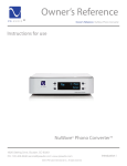
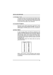
MATELECT
DCPD Crack Growth Monitor
TYPE DCM-1
INSTRUCTION MANUAL
Matelect DCM-1 Instruction Manual
2
Matelect DCM-1 Instruction Manual
MATELECT PULSED DIRECT CURRENT
CRACK GROWTH MONITOR
TYPE DCM-1 and DCM-1I
Thank you for your interest in our product, we hope that it will serve your needs
and prove a reliable tool.
This product has been designed to the highest standard in both electronic and
mechanical design, with careful attention to stability, reliability and electrical safety.
The DCM-1 is an advanced DCPD crack growth monitor that utilises the pulsed direct
current technique to monitor the propagation of cracks within metal specimens
undergoing mechanical testing. Its microprocessor based design and pulsed current
facility have resulted in a compact and lightweight DC system for use in the
laboratory. The DCM-1I is a fully floating version of the DCM-1.
Matelect manufacture the DCM-1 and are pleased to offer applications advice on the
DCPD technique. The DCM-1 complements Matelect's existing range of ACPD
equipment which is traditionally used where greater sensitivity to crack initiation and
propagation is required. Please contact us should you ever require further information
or assistance.
IMPORTANT
Please read these instructions carefully before you use the instrument. Please pay
particular attention to the section that follows on mains operation. For your reference
please also read our terms and conditions of sale printed at the rear of this manual.
Use only a slightly dampened cloth and mild detergent to clean the DCM system.
Never use a solvent cleaner or any fluid.
Please note that there are no user serviceable parts within the DCM-1. Never attempt
to open the instrument case as this will void any warranty. Please contact Matelect
should you ever experience any difficulties.
MATELECT LIMITED
7 Park Place, Newdigate Rd, Harefield, UB9 6EJ UK
Telephone
+44 (0)1895 823334
Facsimile
+44 (0)1895 824300
E-mail:
[email protected]
3
Matelect DCM-1 Instruction Manual
2. MAINS OPERATION
This section applies to all mains operated instruments
PLEASE READ BEFORE OPERATION
Before use, please make sure that the instrument's supply rating is correct for the
location it will be used in. The DCM-1 can be operated on both 100-110 and 220240V, 50/60 Hz mains supplies by appropriate selection on the input voltage switch
(see page 12). Before shipment your instrument will have been set for the commonly
used voltage in your locality.
The instrument must be connected to the mains supply using an IEC mains lead
terminated with the appropriate local mains plug. The unit is supplied with a suitable
lead for this purpose.
When pulsing the specimen current, the instrument will draw substantial currents
through the mains cabling. If cables, extensions cords or supply lines of insufficient
capacity are utilised, then undesirable mains voltage drops may occur during pulsing.
Where the local mains supply is near the bottom limit of the DCM-1 operating range,
such drops could cause the brightness of the LCD graphics display to dim in
synchrony with the current pulse and the pitch of the operating fan to change. Do not
operate the DCM-1 in these conditions - restore the supply's capacity by uprating the
cabling.
The instrument is housed in a metal case for strength and electromagnetic
screening purposes and therefore PLEASE ENSURE that the instrument is earthed
to the mains earth via the IEC connector.
In addition to the fuse that may be present in the mains plug (e.g. UK versions), the
DCM-1 is fitted with an equipment fuse for protection. This fuse is located in the IEC
input socket on the rear panel of the DCM-1. This fuse must be functional if the
equipment is to be operated.
The instrument fuse is rated at 2.5 amperes and is of the 20mm "anti surge" type.
Never replace this with a fuse of a different type or rating as the instrument can be
seriously damaged.
Ensure that the DCM-1 does not come into contact with fluids or corrosive gases and
that it is operated within the temperature range of 0 - 40°C.
4
Matelect DCM-1 Instruction Manual
3. CONTENTS
1.
Welcome ..................................................................................3
2.
Mains Operation.....................................................................4
3.
Contents ..................................................................................5
4.
Overview .................................................................................6
5.
General Description ...............................................................8
6.
Front Panel Description.......................................................11
7.
Rear Panel Description ........................................................14
8.
DCM-1 Preamplifier unit ....................................................17
9.
Connections to the specimen ...............................................19
10. Connection to a testing machine .........................................22
11
Setting up a test ....................................................................26
12. General usage advice ...........................................................29
13. Specifications ........................................................................33
14. Warranty Information.........................................................35
5
Matelect DCM-1 Instruction Manual
4. OVERVIEW
The Matelect DCM-1 system has been designed to allow measurement of crack
growth in metals using the pulsed direct current technique.
The DCM-1 has been produced to replace the ageing DC systems that are common in
laboratories throughout the world, with a modern, sophisticated yet easy to use
instrument. The unit is microprocessor based and all functions are controllable from
five front panel push buttons. The functions selected and the measurement values are
displayed on a graphics LCD screen.
In DCPD work, crack growth is measured by simply passing a constant direct current
through the test specimen and measuring the voltage drop developed across an area of
that specimen. The DCM-1 both sources the constant current and amplifies the
minute voltages generated across the specimen. In effect, DCPD measures specimen
resistance. As a crack propagates the specimen resistance will increase in a way that
can normally be related to actual values of the crack depth.
The currents that are required in DCPD, in order to obtain a measurable voltage, are
of the order of tens of amperes. This requirement has made traditional DCPD systems
large and bulky. Additionally DCPD suffers from problems due to the generation of
thermoelectric EMFs which are of a similar magnitude to the true DCPD signals.
The disadvantages that traditional DCPD suffers from have largely been eliminated
by the use of a pulsed DC measurement method. Here, the current supply to the
specimen is interrupted and pulses of current are passed, instead of a continuous flow.
Measurements are taken both during and in between pulses. These are then compared
in order to reduce noise and remove thermoelectric effects.
For sensitive work, carefully designed voltage amplifiers are required. These need to
be highly stable and as immune to noise as possible. A separate preamplifier greatly
reduces the effect of noise that would otherwise originate from long signal leads.
With careful design, impressive crack growth resolutions of a few tens of microns or
better are possible.
Temperature can markedly alter the characteristics of such voltage amplifiers. It is
therefore important to make them as temperature insensitive as possible. Some
amplifier designs incorporate heaters in order to maintain a constant temperature and
hence reduce the drift, however, the advent of modern electronic techniques have
made this unnecessary. This results in a simpler and more reliable measurement
system.
6
Matelect DCM-1 Instruction Manual
A further enhancement of the DCPD technique is to use two specimens. One of these
is used as the test specimen, whilst the other is used as a reference so that changes in
the DCPD due to environmental changes (e.g. temperature) are eliminated.
The specimens are connected in series so that the same current flows through both.
Two voltage measurement channels are required in this case. This technique is
known as normalisation.
Two channel normalisation can still be performed on a single specimen by using
specialist formulae (available in published scientific literature). In such cases it is
usual for the reference channel to be sited in an area that is not subject to cracking,
although formulae have been developed to handle two channels, both of which
straddle the crack site. Matelect can advise on some of these methods.
The DCM-1 utilises the pulsed DC technique and can source current pulses of up to
50 amperes. All the functions are controlled via 5 front panel push buttons and a
backlit LCD graphics screen.
The DCM-1 is microprocessor based and consists of the main unit and a separate
pre-amplifier unit that is placed close to the test specimen. The preamplifier is not
heated and consists of two highly stable amplifiers for full two channel operation.
The DCM-1I is a variant of the DCM-1 and contains a fully floating current supply
and two fully isolated signal inputs. Isolation of this kind may assist users who wish
to perform simultaneous electrochemical studies.
This manual applies to the DCM-1 and DCM-1I pulsed DCPD units and
preamplifiers. Users who experience any difficulty in operation of the equipment are
advised to contact Matelect at the address given at the beginning of this manual.
Items pertaining to the DCM-1I are highlighted in grey.
7
Matelect DCM-1 Instruction Manual
5. GENERAL DESCRIPTION
The DCM-1 system comprises the following components;
The main display and control unit
The two channel pre-amplifier.
Connection cables.
The main display and control unit comprises the current sourcing and voltage
measurement facilities and the graphics display screen. All functions are controlled
by an internal Z8 microprocessor. In addition to measuring and displaying the DCPD
readings, the main unit also performs a normalisation calculation if the user has
selected two channel operation.
Analogue outputs are provided at the rear of the DCM-1 so that the values of either
the specimen channel, the reference channel and the normalised DCPD value can be
recorded via a computer (suitably equipped with an analogue to digital converter
card) or a chart recorder.
The current is pulsed either automatically via an internal clock control or it can be
pulsed by an external signal, sourced from the user's testing machine (or other
equipment as appropriate). This facility allows the current pulses to be synchronised
to a fatigue testing cycle. Such synchronisation is useful in order to measure the
DCPD at a particular point on the testing cycle since the DCPD can often change
during any one particular cycle. Changes due to crack closure, for example, can be
followed by this method.
The DCM-1 permits external synchronisation on both the peak and trough of the
fatigue cycle (peak tension or peak compression). Additionally synchronisation to the
zero load (cross over) point is also possible. Please see the section on Connections to
the Testing Machine for further details.
A pulse divider facility is also provided. This allows the current to be pulsed at
integer values of the testing machine waveform. This minimises the current-on time
and hence reduces specimen heating. It is also useful to reduce electrochemical
effects.
All current and signal gain (amplification) levels together with the pulse
synchronisation options are set using a menu system that is displayed on the front
panel graphics screen. The menu system is simple to operate and requires little
explanation. To assist the user, however, this manual gives an example of how to set
up a typical test regime.
8
Matelect DCM-1 Instruction Manual
The separate preamplifier unit has inputs for two channels and should be sited as near
to the specimen as possible. It incorporates high stability, low drift amplification
circuitry which conditions the minute DCPD voltages and supplies them in amplified
form to the main unit.
The main unit digitises the incoming DC signals from the preamplifier and displays
them on the graphics screen.
In general, the DCPD system should be configured as shown in Fig.1. All the
required cables for this set-up are provided with the DCM-1 and these are illustrated
overleaf in Fig 2.
In the example shown, two specimens are used, one as the test piece and the second as
a reference. It is usually advisable to use a reference test piece in DCPD studies,
although other configurations are possible. Further operational advice is given
throughout this manual and detailed topics are covered in the section entitled, General
Usage Advice.
Main Unit with display
X/Y analogue output
X analogue output
TO PC
OR CHART
RECORDER
Machine cycle input
current
outputs
FROM
TESTING
MACHINE
pre-amplifier
screened signal
cables
High capacity
connecting
cables
specimen
reference
Fig 1. General schematic view of a typical DCM system set-up
9
Matelect DCM-1 Instruction Manual
Test machine cycle (BNC) to DCM-1 cycle input
X/Y or X output (BNC) to chart recorder or acquisition system
preamplifier output to DCM-1 preamplifier input
preamplifier X input to specimen
preamplifier Y input to specimen
specimen to reference current lead
specimen to positive DCM-1 current terminal
reference to negative DCM-1 current terminal
IEC Mains input (IU-1) to Local mains plug
Fig 2. Cables supplied with the DCM-1 system
10
Matelect DCM-1 Instruction Manual
6. FRONT PANEL DESCRIPTION
The front panel of the DCM-1 is shown in Fig 3. The controls are simple to
understand and all test parameters are set using the five front panel push buttons.
MACHINE CYCLE
IN
MATELECT
Please select variable to adjust
Set current
Set measurement point
Set measurement frequency
Set X and Y gains
Set filter time constants
Run/Stop
ON
MATELECT
DCM-1
2 CHANNEL PULSED DCPD SYSTEM
SELECT
FUNCTION
SELECT
PREAMPLIFIER
INPUT
CURRENT ON
Fig 3. The front panel of the DCM-1 main unit
1.
Graphics Display
This is a high resolution LCD graphics panel with a cold cathode fluorescent
backlight. Like all LCD displays, the contrast seen by the observer is viewing angle
dependant and therefore the contents of the display may not be visible from all angles.
The contrast has been factory set to provide the best compromise between visibility
and viewing angle.
The display determines the active operating temperature range of the DCM since too
high an ambient temperature will cause the screen to darken. Too low a temperature
will result in a slow response to changes in the displayed characters. In both cases the
display will return to normal when the ambient temperature is within an operating
range of 10 to 35 degrees Celsius.
NOTE: The LCD panel is sturdy but should only be cleaned with a slightly moistened
cloth. Do not use a chemical cleaner or damage to the display surface will occur. Do
not press down on the display area and never use a sharp instrument such as a pen to
tap or poke the surface.
11
Matelect DCM-1 Instruction Manual
2.
Selector push buttons.
Menu options are selected and chosen by use of these push buttons. Additionally the
keys are used to increment or decrement experimental parameters such as the value of
the applied specimen current or signal gain.
The four black buttons are cursor keys which control the movement of the display
cursor and increment or decrement values. The direction of cursor movement is
indicated by the arrow legend positioned alongside each button.
The central red push button is used to activate a particular option once this has been
selected by the cursor keys. The red button acts as an "enter" key.
The keys are pressed and released once to move by one position or to alter a value by
the minimum increment. There is no repeat function on each key, so successive key
presses are required to further alter a value or position.
Numerical parameters are not altered on a cyclical basis on every menu option. This
means, for example that once a maximum value has been selected for a parameter or
digit, further changes are only possible by using the decrementing push button.
3.
Machine cycle input socket
This is a four pin, polarised female socket which accepts a waveform signal from an
external source, usually the testing machine, and permits synchronisation of the
current pulses supplied by the DCM-1 to the input signal. A cable is provided for
connection between this socket and the testing machine. The input waveform needs
to be within certain specified limits of both frequency and amplitude in order to allow
reliable synchronisation. The pin configuration of this connector is given, together
with further details on the input signal range in the section on Connections to the
Testing Machine.
NB. When connecting the supplied cable to this connector, locate the protrusions on
the cable mounted socket with those on the connector. The plug should then enter the
socket. Only then should the screw collar be tightened onto the socket.
4.
Preamplifier In socket.
This is a twelve pin polarised female socket that connects via the cable supplied to the
rear of the DCM-1 preamplifier box.
NB. When connecting the supplied cable to this connector, locate the protrusions on
the cable mounted socket with those on the connector. The plug should then enter the
socket easily. To remove the plug, simply grasp the sliding collar and pull.
12
Matelect DCM-1 Instruction Manual
5.
ON indicator.
This consists of a red LED which lights to indicate that power has been applied to the
DCM-1.
If this indicator remains off after external power has been applied, turn off the mains
supply then READ the section on Mains Operation at the start of this manual Check
that the mains cable has been fully pushed into the rear panel IEC mains input socket
and that your mains supply is available (use another appliance which you know is
functional in order to test that the mains supply is present). If these are in order,
check the fuses both in the instrument's IEC connector and in your mains plug (if a
fuse is fitted). Contact Matelect if none of these checks provides a solution.
6.
Current On indicator
This green LED flashes in unison with the current pulse as supplied to the test
specimen. It remains off during the periods when the specimen current is off.
Because of internal limiting circuitry, the current pulses can never be closer than
about 700mSec apart. The indicator should, therefore, never pulse at frequencies
greater than this even when external control waveforms of greater than 1 Hz are
applied.
13
Matelect DCM-1 Instruction Manual
7. REAR PANEL DESCRIPTION
The rear panel of the DCM-1 is shown below in Fig 4. Located on this panel are the
mains input socket, analogue and RS232 outputs, voltage selector, auxiliary and
current supply outputs. A heatsink is also positioned on this panel together with its
cooling fans. The air vents at either side of the heatsink and the air vent along the
bottom edge of the rear panel should never be obstructed. Failure to adhere to this
can cause serious damage to the DCM-1.
If the fan units fail to operate, the DCM-1 should not be used. Please contact
Matelect in the unlikely event of this ever happening.
SER.
X
Y
X/Y
COMMON
EARTH
CURRENT
OUT
AUX.
VOLTAGE
SELECTOR
Fig 4. Schematic of the DCM-1 main unit rear panel
1.
Mains input socket.
This is a standard IEC mains input socket with integral line filter, mains switch and
mains fuse. A suitable lead, terminated with a local mains plug, will have been
supplied with the DCM-1. If this is missing, only use an approved mains connector
lead in the IEC socket.
The instrument is fused with a 2.5 ampere quick blow 20mm fuse. If this fails for
whatever reason, disconnect the equipment from the mains supply and replace the
fuse with one of the same rating and type. DO NOT use a fuse of a higher rating as
permanent damage may result to the DCM-1. If the local mains plug also incorporates
a fuse, then this should be of a similar rating to the fuse within the IEC socket.
14
Matelect DCM-1 Instruction Manual
2.
Serial Data (RS232) output socket.
This is a 9 way D type male socket. The pins are configured as a standard RS232 9
way connector. The data format and pin out details can be obtained from Matelect.
Software for data acquisition via the serial data link is available from Matelect.
3.
Analogue Outputs.
The DCM-1 provides three analogue outputs of the measured DCPD values. These
are available as analogue voltages on the three BNC connectors marked X, Y and
X/Y. The X and Y outputs will ideally be in the range from 0 to 2 Volts, although
approximately 3 volts is the maximum possible. These outputs correspond exactly to
those shown for the X and Y channels on the front panel graphics display. The X
channel should be connected to the test specimen and the Y channel to a reference
specimen.
If a reference signal is being employed, then the user should monitor the X/Y output
which exactly follows the value of the X/Y ratio shown on the graphics screen. This
voltage can range from 0 to about 10 Volts.
All outputs are buffered and are suitable for connection to a chart recorder or
computer data acquisition system. A chart recorder cable is supplied with the DCM1. If any other cable is used, please ensure that the correct polarity is maintained - the
Common of the output is always the outer portion of the BNC connector.
4.
Common and Earth Terminals.
The circuit common of the DCM-1 is electrically isolated from the case Earth. If it is
desired to connect the common to earth, a wire link can be used between the Common
and Earth terminals.
Isolation of the Common is useful if external peripherals are connected to the DCM-1
such as chart recorders. If their signal common is connected to Earth, an Earth loop
could occur, should the DCM-1's common also be connected to Earth. Such loops are
sources of signal instability and should therefore be avoided.
5.
Current output terminals.
These screw action terminals are coloured Black and Red.
For a DCM-1 Red is actually circuit common and the Black is circuit negative,
however, this is of no consequence to the user who should adhere to the colour code
rule as given in the section entitled Connections to your Specimen.
For a DCM-1I, the current terminals are fully isolated from the Common of the main
circuitry.
15
Matelect DCM-1 Instruction Manual
The appropriate cables (supplied) should be used between these terminals and the
specimen/reference. It is advisable to attach the cables and specimen to the current
terminals before attempting to supply a current. Making a connection to the supply
whilst the DCM-1 is pulsing a current will cause sparking at the point of connection.
This is not good practice since sparks are sources of electrical noise which can often
upset sensitive electronic equipment.
If the current connections are not properly made an error message will appear on the
front panel graphics display to alert the user as soon as an attempt is made to source a
current. This will also occur if the resistance of the specimen-cables-DCM-1 circuit
is high enough to cause the voltage compliance of the current source to be exceeded.
If the compliance limit is exceeded, check the current connections and reduce the
value of the set current if necessary. In certain circumstances, highly inductive
specimens or cable set-ups can cause the compliance error message to appear.
Altering the positions of the current leads may solve this problem.
6.
Auxiliary power socket.
This socket is used to power peripheral instrumentation that can be connected to the
DCM-1, for example, a signal multiplexing system. The socket is wired as follows;
Pin 1 Positive 17 volts unregulated, 100mA maximum (right hand)
Pin 2 Circuit common
Pin 3 Negative 17 volts unregulated, 100mA maximum (left hand)
The supplies are fused and current limited to prevent damage to the DCM-1 should a
short circuit occur. Only Matelect approved apparatus should be connected to this
socket.
7.
Voltage selector switch.
PLEASE READ THE SECTION ON MAINS OPERATION at the beginning of this
manual before attempting to alter the position of this switch.
The switch permits the DCM-1 to be used with either 110-120 or 220-240 mains
supplies. The DCM-1 is factory adjusted to the correct mains input voltage before
shipment but users may wish to alter this depending on the location of the instrument.
A wide blade screwdriver should be inserted into the slot within the switch and
rotated to the appropriate input voltage (as marked on the switch).
CARE! Operation of the DCM-1 with this switch incorrectly positioned will cause
serious permanent damage to the unit. When altering the switch position ENSURE
that the mains supply is disconnected from the DCM-1.
16
Matelect DCM-1 Instruction Manual
8. DCM-1 PREAMPLIFIER UNIT
Fig 5. shows the front and rear panel views of the separate DCM-1 pre-amplifier. The
connectors on these panels will mate with the appropriate cables supplied by
Matelect. Should it be necessary to lengthen the cables, please contact Matelect for
further advice. The pin configurations for each of the signal input connectors are
given in Fig 6. Users should note that Matelect can accept no responsibility for
damage caused by incorrect cabling or connections.
NB. When connecting the supplied cables to the connectors, locate the protrusions on
each cable mounted socket with those on the mating connector. The plug should then
enter the socket. Only then should the screw collar be tightened onto the socket (for
the signal inputs). The system unit output cable is terminated a push/pull locking
connector.
MATELECT LIMITED
INPUT X
INPUT Y
Front panel of preamp
DCPD Preamp
Output to system unit
Rear panel of preamp
Fig 5. Schematics of Preamplifier front and rear panels
17
Matelect DCM-1 Instruction Manual
LARGE LOCATING LUG
2
1
4
3
1. X/Y SIGNAL POSITIVE (red on cable)
2. Not connected
3. X/Y SIGNAL NEGATIVE (black on cable)
4. Circuit common (not earth) (screen on cable)
CHANNEL X and CHANNEL Y input
sockets on preamplifier front panel
Fig 6. The pin configuration of the X and Y input sockets located on the preamplifier
The DCM-1I contains isolated signal inputs which are fully floating with respect to
the circuit Common of the main instrument. Isolation is performed by a voltage to
frequency converter, feeding a frequency to voltage converter through an optocoupler
The pre-amplifier should be mounted close to the specimen to minimise noise and it
should not be subjected to temperature gradients across its external dimensions.
Further details on these points are given in the following section.
18
Matelect DCM-1 Instruction Manual
9. CONNECTIONS TO THE SPECIMEN
GENERAL
In general, if no specific test regime has been chosen by the user, the configuration
shown in Fig 1, should be employed.
Two specimens are utilised, one acting as the test specimen and one acting as the
reference specimen. A reference specimen is used to counter any thermal effects that
occur due to a variation in the ambient temperature. The value of the DCPD from the
test specimen is normalised via a division using the DCPD value from the reference
specimen. This method will only work if both the test and reference specimens are
subjected to the same ambient temperature and also that any temperature variations
are uniform in nature. For example, bright sunlight shining only on one side of the
test or reference specimen can seriously affect the DCPD values obtained.
CONNECTIONS
Users must obey the usual sign conventions when connecting the current and signal
cables to the test and reference specimens. The signal-high wire on the signal cable
(coloured red) should always be connected to the side of the specimen nearest the Red
current terminal. The signal-low (black) wires should similarly be situated nearest the
connection to the black current terminals (see Fig 1).
If the colour code is not followed, an error message will appear on the front panel
graphics display alerting the user, once current has been supplied to the test pieces.
Users should always employ the standard cables as supplied by Matelect with the
DCM-1 system. If the cables have had to be lengthened, please ensure that the same
type of cables are used and that the connections to the DCM-1 are made correctly.
Unfortunately Matelect cannot accept responsibility for any damage caused to the
DCM-1 by incorrect cable connections.
If a lower rating of current cable is utilised (below ca. 70 amperes continuous) users
may find that the voltage compliance of the current source is reached well before it is
possible to pass the maximum current. This may especially be applicable for large or
high resistivity specimens.
19
Matelect DCM-1 Instruction Manual
CONTACTS
Securing the current cables to the specimen is best accomplished using a large gauge
threaded fastener, such as a machine screw. Ensure that the contact surfaces are free
from corrosion and any poorly or non-conducting surface layers, as these can also
force a lower maximum current by causing the voltage compliance to be reached.
The signal contacts can be made using finer screw fasteners or they can be spot
welded. Other methods such as conductive glues or soldering can be used for
specialist applications.
For test specimens that are to be submerged in an electrolyte (e.g. water) it is
important to use fastening materials and methods that are electrochemical compatible.
Corrosion of the current contacts can be especially problematic in DCPD studies but
the use of pulsed current as opposed to continuous, has reduced these effects
dramatically.
THERMOELECTRIC EMFs
Thermoelectric EMFs are generated wherever dissimilar metals are in contact with
each other. These can be of the same order of magnitude as the value of the actual
DC signals due to the specimen resistance. Such EMFs can therefore destroy the
integrity of DCPD results. Again the use of pulsed currents has effectively eliminated
the thermoelectric effects.
Pulsing allows the EMFs to be measured during the current OFF period. The OFF
reading is subtracted from the ON reading thus eliminating the thermoelectric EMFs.
This method assumes that no temperature change occurs between the two sets of
readings. This is a fair assumption unless abnormally high rates of heating or cooling
are occurring.
NOISE
All cables leading from the specimens to the pre-amplifier should be shielded from
stray EM radiation and as short as practicable. Remember that the voltage resolution
at the specimen surface ranges from a few hundred nanovolts to a few tens of
nanovolts (dependent upon gain) so any noise can seriously affect the integrity of the
measurements.
OTHER CONSIDERATIONS
The preamplifier should be sited close to the specimen. The preamplifier should not
be subjected to uneven heating of its enclosure as this can cause errors in the
measured DCPD. A general change in ambient temperature does not pose a problem
as the thermal drift of the pre-amplifier circuitry is extremely low.
20
Matelect DCM-1 Instruction Manual
Unlike ACPD, DCPD specimens should be electrically isolated from the test machine.
A significant portion of the DC current will flow through the testing machine to earth
if this rule is not followed. Damage to equipment is unlikely to occur but the voltage
readings obtained under such a situation will be worthless. Additionally any
alternative current paths may not exhibit a constant resistance during a test, so
specimens must be always be electrically isolated.
Most users have their own method of specimen isolation but in general, any thin strips
of paper or adhesive tape can be used to insulate the specimen surface from the testing
machine grips. In the case of standard CT specimens for example, the pins that
permit the specimen to be stressed must also be isolated from the specimen.
Conventional pins are usually machined to be a tight fit into the specimen locating
holes so as to minimise "slack". Smaller pins will therefore have to be machined in
order to permit insertion of an isolating layer.
21
Matelect DCM-1 Instruction Manual
10. CONNECTION TO A TESTING
MACHINE
PULSE SYNCHRONISATION
For fatigue studies, the pulses of current as supplied by the DCM-1 can be
synchronised to an external waveform source. This waveform is usually derived from
the user's testing machine. Since the DCPD values are measured during a current
pulse, the synchronisation facility permits the acquisition of DCPD values at
particular points on the load or displacement cycle. This facility can, for example, be
used to investigate crack closure phenomenon.
A cable is supplied to enable users to connect the DCM-1 to a testing machine's
cyclical output. The waveform is usually available on the testing machine as a
buffered BNC output of either the load or displacement values. These are analogue
voltages usually scaled according to the load cell amplitudes chosen by the testing
machine user.
The following diagram illustrates the connections to the input socket on the front
panel of the DCM-1 main unit.
Large locating lug on socket
2
1
4
3
1. Signal low (BNC outer)
2. +15V supply (for peripherals)
3. Signal high (BNC centre pin)
4. -15V supply (for peripherals)
Machine Input socket on
front panel of the DCM-1 main unit
Fig 7. Testing machine input socket pin configuration
It is important to note that the synchronisation circuitry is not capable of following all
types of input signal, over all values of input amplitude and frequency. The limits are
given overleaf.
Should your input signal fall outside the range, reliable
synchronisation may not be possible. Matelect may be able to assist users with
specific synchronisation needs but this will usually require non-standard
modifications to the existing circuitry.
22
Matelect DCM-1 Instruction Manual
Your test machine manufacturer should be contacted for further advice on the
provision and location of a suitable waveform output.
The input ranges have been chosen to match closely the likely amplitudes and
frequencies normally employed by testing machine users. If your settings are not
within this range you should consider using the internal pulse generator facility of the
DCM-1.
SIGNAL INPUT RANGES
For reliable operation, the synchronisation circuitry requires:
1. A signal amplitude of (+10 volts to -10 volts) maximum
2. A signal amplitude of (+2 volts to -2 volts) minimum
3. A maximum signal frequency of 10 Hz
4. A minimum signal frequency of 0.1Hz
5. A sinusoidal or triangular wave signal
Signals not within this specification may still permit synchronisation but the
reliability will degrade with a divergence from these limits.
POINTS TO NOTE
Synchronisation can be set to occur on the peak, trough or zero crossing portions of
the input waveform.
The DCM-1 does not have to pulse at each synchronisation event since a pulse divider
facility is provided whereby the user can set pulse intervals of between 1 and 9999
cycles.
Signals with a DC offset, e.g. -2.5 to +7.5 volts (equivalent to a 2.5 volt offset) can
still be synchronised to - providing the offset does not cause the signal to range above
the +/- 10 volts maximum and that either Peak or Trough mode is selected.
In the Zero Cross Over mode, synchronisation will only occur if the waveform
actually crosses zero. DC offsets are therefore tolerated provided they do not cause
the whole waveform to become either positive or negative in polarity. Once again
overall signal amplitudes should not exceed the limits given above.
The machine cycle input is voltage and current protected to 50 V continuous or 250 V
intermittent but users are advised not to test these limits!
The current source within the DCM-1 is not permitted to pulse faster than
approximately 1.5 Hz. However, the synchronisation circuitry can still accommodate
waveform signals up to 10 Hz in frequency. For such signals, synchronisation will
still take place at the peak, trough or zero point, except that it will occur after the
passage of the appropriate number of waveform cycles commensurate with the 1.5 Hz
limitation. Some of these points are illustrated in the schematic overleaf.
23
Matelect DCM-1 Instruction Manual
TEST MACHINE
WAVEFORM
CURRENT PULSES
SYNCHRONISED TO
PEAK TENSION
CURRENT PULSES
SYNCHRONISED TO
PEAK COMPRESSION
CURRENT PULSES
SYNCHRONISED TO
ZERO CROSSING
CURRENT PULSES
SYNCHRONISED TO
HIGH CYCLE PEAK
TENSION
Fig 8. Waveform synchronisation examples
Synchronisation to waveform frequencies down to 0.01 Hz is possible providing that
the signal amplitude is raised above +/- 8 volts. However at such low frequencies
there is little point in using synchronisation as the amount of data collected will be
quite small. It therefore may be better to use the internal pulse generator and log the
maximum number of data points available.
24
Matelect DCM-1 Instruction Manual
The load and displacement outputs from most testing machines are scaled according
to the following criteria:
1.
2.
The range chosen for a particular load cell
The percentage amplitude within the chosen range of the fatigue cycle.
For example, a 100kN load cell might be used on one of 4 load ranges, 10, 20, 50 and
100kN. Within each range it is possible to apply loads of zero to 100% of the range
with negative loads (compression) also allowed.
The maximum analogue output on any range is usually 10 volts and this corresponds
to 100% of the particular range. Thus on a 20 kN range, operating at +/-50% load
capacity, the load would range from +/-10kN and the analogue output would range
between +/- 5 volts.
This example indicates that for reliable synchronisation, the load (or displacement)
should never be below 20% of its range (for a +/-10 Volt testing machine) and ideally
it should correspond to 7.5 volts or 75%. For values below 20% a separate signal
amplification unit (type LCC-1) can be used to boost the signal levels before they
enter the DCM-1. Please contact Matelect for further details.
ANALOGUE SIGNAL INPUT
Some way of recording the DCPD is usually required by the user. It is not practical to
take readings from the front panel display although still perfectly possible. Analogue
voltage outputs are therefore provided on the rear panel of the DCM-1 main unit and
these can be connected to a chart recorder to provide a continuous and permanent
record of the DCPD values. It is also possible to digitise these signals using an
analogue to digital converter card fitted into a personal computer. In this way the data
can be stored for later retrieval and processing.
Many of the newer testing machines incorporate advanced digital functions which
often include the provision of auxiliary inputs to internal A-D converters. The
analogue voltage from the DCM-1 can thus be easily input into the testing machine,
stored and displayed against and together with various other parameters. Please
contact your testing machine manufacture for advice on such facilities.
25
Matelect DCM-1 Instruction Manual
11. SETTING UP A TEST
Please read all the previous sections within this manual before commencing to set up
a test.
The simplicity of operation of the DCM-1 precludes the need for elaborate
explanation of the setting up options. In this section, therefore, the various options
available to the user are described with the aid of a standard set-up routine.
Once experienced in the operation of the DCM-1, users are not required to rigorously
follow the following set-up. Indeed with experience, the DCM-1 user will wish to use
his or her own set-up parameters which have been optimised for a particular specimen
or test.
Providing the precautions and recommendations already described in this manual
have been followed, no damage can be done to the DCM-1 by a non-standard
combination of menu options, so the user should feel free to experiment with the
parameters in order to achieve an optimum test result.
A BASIC FATIGUE TEST USING THE DCM-1
This example describes a fatigue test set-up, with current pulse synchronisation and a
reference specimen. It is designed as an illustration of the options available and
should not be considered a full and exhaustive description of the procedures involved
in such a test.
1.
If possible, perform a set-up test with the specimens not attached to the testing
machine as follows.
2.
Connect the system components as shown in Fig 1. Remember to follow the
colour code for the connections to the specimen. Use only Matelect cables
where specified. Ensure all connections are firm and properly made. Connect
the analogue outputs (in this case X/Y) to a chart recorder or acquisition
system.
3.
Connect the DCM-1 to the main power and activate it using the rear panel
mains switch. The front panel display should light and after a short delay, the
Main Menu will appear. Allow at least 30 minutes warm up time (see the
section entitled Usage Advice).
4.
Use the cursor keys to travel between each option and use the central red key
to alter the option, input information or make a choice. Start at the beginning
of the menu and work downwards. If, after setting all the values, a parameter
has inadvertently not been set, the microprocessor will politely inform you of
your error. At any time you can return to a menu option and change it without
difficulty.
26
Matelect DCM-1 Instruction Manual
5.
Set the test current. This can be set between zero and 50 amperes in steps of
10mA. For a typical CT specimen try 30 Amps.
6.
Set the measurement point. If pulse synchronisation is required, set either
peak tension or compression or zero load. If the test will be under constant
load select N/A. For our example select peak tension.
7.
Select measurement frequency. In our example select cyclic load. Select
steady load if a simple load-extension test is being performed.
A
supplementary menu will ask you how often you wish to pulse the current and
hence measure the DCPD values. Set 0001 for every cycle, set 0002 for
every other cycle, 0003 for every third cycle etc. up to 9999 cycles. If a steady load
had been chosen, the measurement frequency will be in seconds rather than in
cycles. Try 0001.
8.
Set the amplification value (gain) of the DCM-1 system. The gain can be
varied between 1000 times and 50000 times in steps of 1000. See the
following section for recommendations on the most suitable setting. As an
example select 1000.
9.
Select the filter time constant. This should always be set to 200mSec unless
users wish to experiment with shorter periods. See the following section on
Usage Advice for further details.
10.
Begin the test. Use the Test Settings option to check the results of your set-up.
Test Settings pulses the current at 1 second intervals through the specimen.
Therefore you do not require a synchronisation waveform for this test. Any
errors in the current or signal connections will now be indicated.
11.
If the readings obtained on channel X and Y are each about 1 volt, then the
current and gain settings are ideal. Please read the following section on Usage
Advice for further details.
12.
To stop the test, press and hold down the RED button until you are returned to
the Main Menu.
13.
Remove the DCPD connections if required and attach the specimen to the
testing machine, and perform your usual test machine set-up. Ensure that the
machine cycle input socket has been correctly connected to your testing
machine output and that sensible values of the cyclic frequency and amplitude
have been set (see section on Connections to Your Testing Machine).
14.
Check the electrical isolation of the test specimen from the testing machine.
Attach the current and signal cables to the specimen, locate the reference and
preamplifier close to the specimen but away from sources of noise and uneven
heat.
27
Matelect DCM-1 Instruction Manual
15.
Commence the fatigue test, and the DCPD test (using the "Begin test using
values set" option on the Run/Stop sub menu.)
16.
The readings obtained should be similar to those observed during the set-up
test. If they are not check the level of noise on the signal by observing the
front panel readings (it should be about two digits maximum). Also check the
integrity of the connections and the isolation of the specimen. Contact
Matelect for further advice if a problem remains.
Remember that to translate voltage or voltage ratio into crack depth, it is usual to
perform a calibration test whereby the readings are related to the crack depth as
measured by another technique. The following section on Usage Advice gives further
details on calibration.
28
Matelect DCM-1 Instruction Manual
12. GENERAL USAGE ADVICE
This section deals with some of the finer points relating to DCPD and the DCM-1 in
particular.
GAIN VERSUS CURRENT VERSUS NOISE
In general the lower the gain setting of the DC amplifiers, the lower the observed
noise. Therefore in order to obtain a respectable signal level, a high current may be
required. Naturally the value of the current depends upon such parameters as
specimen size and contact spacing. Users should aim to obtain a signal level of
between 0.5 and 1 Volt for channels X and Y by appropriate adjustment of the current
and gain.
Whilst it is advisable to use the lowest appropriate value of the gain, users must note
that high specimen currents can lead to specimen heating, especially around an
advancing crack tip. In such circumstances a further variable can be brought into play
- the pulse frequency. This can be adjusted by the user from within the Measurement
frequency option of the Main Menu. To reduce specimen heating a long delay
between pulses should be chosen.
From the above example it is clear that several operating parameters are closely
dependent upon each other and changing one will invariably affect the other. Only
through experience can these variables be reconciled.
NOISE AND RESOLUTION
The noise on the readings is usually described in terms of the digit flicker. Naturally
the flicker is greater, the higher the gain setting. The flicker should be +/- 1 digit at a
gain of 1000, rising to +/- 3 digits at gains in excess of 30,000. The small change in
noise with gain illustrates the excellent noise specification of the pre-amplifiers. The
noise levels are largely determined by what is termed pixel noise within the digital
components of the DCM-1.
Since the displayed voltage resolution is 1mV, the voltage resolution of the DCM-1,
at the specimen, ranges from 1μV at a gain of 1000 to an impressive 20nV at a gain of
50,000. The noise figures quoted above correspond to voltage levels of 1μV to 60nV
at the respective gains.
Crack length resolution is determined by both the theoretical resolution and the noise
specification. A typical static calibration test (see the section on Calibration) results
in a change of voltage of around 50 digits (50mV) per millimetre. This equates to a
theoretical resolution of 20 micrometres. In practice the noise specification would
affect this value but nevertheless 50 micron resolution is readily achievable (ignoring
external sources of noise).
29
Matelect DCM-1 Instruction Manual
VOLTAGE READINGS
Please note that the maximum displayable voltage reading on either channel X or Y is
3 volts, however signal saturation will occur at voltage levels above 2.5 volts. It is
therefore advisable to question the integrity of any voltages above 2.5 volts. The X/Y
value can, however, reach 10 volts with no saturation problem.
The recommended starting voltage of between 0.5 to 1 Volt will usually ensure that a
propagating defect will not exceed the 2.5 Volt maximum.
X/Y CONSIDERATIONS
Please remember that the maximum sensitivity of measurement is achievable when X
and Y channels return a similar voltage level. If one or other of these values differs
substantially from its partner, errors in the X/Y division can occur. Thus a low X
value when divided by a much larger Y value will result in a small X/Y ratio. Any
noise on the Y signal will cause a large change in the X/Y ratio.
Similarly, a low Y value will result in a high X/Y ratio, and any noise on the X or Y
signal will cause a large change in the X/Y output. Additionally, the X/Y ratio is
limited to a maximum of about 12 volts by internal circuitry constraints.
In general, therefore, maintain X and Y at similar levels so that X/Y remains
approximately within the 0.5 to 1.5 range.
Naturally, this may not always be
possible, especially if the signal probe spacings are substantially different between the
test and reference specimens.
WARM UP CONSIDERATIONS
Ideally, the DCM-1 should be allowed to warm up after switch on for 30 minutes to
allow the electronics to thermally equilibrate. If the unit has been moved and was
subjected to a large difference in temperature between localities, please allow a
correspondingly longer warm up period.
Once a specimen has been connected to the DCM-1 and the test has commenced, the
actual process of passing a current through the specimen will inevitably cause a rise in
the specimen temperature. Since DCPD basically involves the measurement of
resistance, such a temperature rise will alter the measured X and Y values. In theory
X/Y should remain constant assuming the temperature change affects both X and Y
channels similarly. This may not always be a fair assumption as cooling rates may
differ between specimens, depending on their locality.
In addition, users must ensure that both the specimens and pre-amplifier unit are
warmed evenly by the external ambient. Localised warming can dramatically alter
DCPD results, both by the change in specimen resistivity and by the occurrence of
thermoelectric EMFs.
30
Matelect DCM-1 Instruction Manual
CALIBRATION CURVES
The translation of voltage measurements into crack depths is usually performed via a
calibration curve. Values of the voltage are plotted against crack depth as measured
by some other technique such as optical observation. Unfortunately, unlike the linear
relationship between crack depth and voltage present in ACPD studies, DCPD
calibration curves are not normally linear and therefore many more test points are
required in order to accurately define the calibration. Once again specimen geometry
plays a significant role in the shape of the calibration curve.
Various formulae and models have been produced by workers within the DCPD field
to describe and predict the shape of the calibration curve. These models are usually
confined to specific specimen geometries but their existence permits simpler
calibrations. Most of these models are available in the published literature and
Matelect are happy to provide applications advice on these matters.
A simple calibration can be obtained by performing a saw cut experiment in which a
progressively deeper slit is made in a test piece using a hacksaw or ideally, a rotary
blade whose depth of cut can be precisely defined. Between each saw cut, the blade is
removed and the voltage readings noted, together with the cut depth. A typical saw
cut calibration is shown in Fig 9.
Depth (saw cut) (mm)
12
10
8
6
4
2
0
1
1.1
1.2
1.3
1.4
1.5
1.6
X/Y
Fig 9. A typical quick saw cut calibration curve
31
Matelect DCM-1 Instruction Manual
FILTER SETTING
It is strongly recommended that users always select the 200mSec filter position since
values below this produce a degradation in the noise performance.
MICROPROCESSOR CONSIDERATIONS
The Z8 microprocessor that forms the heart of the DCM-1, like all computers can
sometimes cease to function or "crash". Should this occur, the only option is to reset
the DCM-1 using the mains switch. Allow 5 seconds before re-applying power to
permit the voltage levels within the unit to decay.
A crash is usually caused by unusually strong amounts of extraneous electrical noise.
This can originate from nearby equipment, especially that which is switching or
controlling large currents.
The DCM-1 is housed in an earthed metal enclosure which acts as an effective
Faraday cage and ensures a high immunity to extraneous noise. Both front and rear
panels are part of the earthed cage. It is therefore imperative, both from a safety
viewpoint and that of noise immunity, to ensure that the enclosure is earthed via the
mains supply lead.
Should your unit continually crash please contact Matelect for further advice.
Extraneous noise may also seriously degrade the performance of the DCM-1. If the
digit flicker observed on the X or Y channels is substantially greater than the noise
figures quoted in this text, users should take steps to reduce the electrical noise in the
locality.
32
Matelect DCM-1 Instruction Manual
13. SPECIFICATIONS
GENERAL:Two channel (reference and specimen) PULSED DCPD unit, housed in a
portable enclosure that can either be bench or rack mounted. Z8 microprocessor
controlled main unit with separate DC pre-amplifier unit. Cold cathode fluorescent
backlit super twist nematic LCD graphics panel, 240 x 128 pixels.
ELECTRICAL SPECS.
Current:
Variable PULSED 0A to 50A in steps of 10mA
No minimum load required
Voltage compliance of 4.5V.
Value is set by a front panel key pad, and indicated
on a front panel backlit graphics LCD display.
Current stability is 0.01%
Noise on supply is below detection limits of the DC amplifiers.
Fully isolated current supply (250V) for DCM-1I option
Voltage Amplification
Separate, non heated, dual pre-amplifier unit
Two amplifiers are used per effective channel (X monitors
crack site, Y monitors reference site)
Gain setting via front panel keypad
Total gains of 1000 to 50000 in steps of 1000,
selectable with the amplified output displayed
on the graphics LCD display.
Front panel display of value of both
X value, Y value and the ratio X/Y
Noise (referred to input) is less than 500pV (pico)
per root Hz or 500nV (nano) peak to peak over the
measurement bandwidth or +/- 1 digit at a gain of 1000.
Drift: less than 200nV (nano) per degree C
Maximum resolution: 20nV (nano)
Common mode rejection ratio (CMR) better than
120dB from DC to 100Hz.
Fully isolated voltage inputs (both X and Y) for DCM-1I option
ADDITIONAL FEATURES:
3 position Filter provided to further remove noise
Filter selectable in OUT, 20mS or 200mS (milli) modes
DCPD measurement synchronisation: Measurement of
DCPD can be chosen to occur at the maximum, or minimum
33
Matelect DCM-1 Instruction Manual
or cross-over positions of the load cycle waveform (either
triangular or sine) of the testing machine.
Synchronisation requires testing machine input. of (+/-)2-10V
over frequency range 0.1 to 10 Hz with operation outside
this range possible.
Pulse divider: This allows current to be pulsed at multiples of
the testing machine cycle. This minimises current ON time
and hence reduces specimen heating associated with DC systems
Pulse divider has variable period - up to one in every 9999 cycles.
Analogue output of amplified DC signals.
RS232 output of amplified signals and X/Y ratio.
POWER:
220-240 or 110-120V AC input, 50 or 60 Hz line frequency by
appropriate user selection.
MAINS INPUT:
Via Earthed IEC connector
LINE FUSE:
One 20mm 2500mA antisurge fuse fitted to rear IEC
connector
DIMENSIONS
Without handle
360 x 310 x 155 mm (W x D x H) (main unit)
115 x 95 x 47 (pre-amplifier)
MECHANICAL
Cast aluminium frame with pressed aluminium alloy panels
finished in standard RAL powder coat.
Preamplifiers housed in extruded aluminium enclosure
finished in epoxy powder coat
Adjustable tilt handle (no cost option)
OPERATING TEMPERATURE RANGE
0 - 40 Degrees Celsius for electronics
10-35 Degrees Celsius for graphics display
MASS
SEALING
STANDARD
34
12Kg
To IP20
Constructed in accordance with CEI/IEC 1010-1 1990
Matelect DCM-1 Instruction Manual
14. WARRANTY AND SERVICE
INFORMATION
The following text is an extract from our standard conditions of sale. It covers
the terms of warranty and liability only. Please refer to the full text, supplied
upon delivery of the goods or contact Matelect Limited.
Extract 6. WARRANTYItems sold by the company are warranted only as stated below.
Subject to the exceptions and upon the conditions specified below, the company agrees to correct,
whether by repair or, at it's election, by replacement, any defect of materials or workmanship which
develops within twelve months after delivery of the instrument to it's original purchaser by the
company or by any authorised representative provided that investigation and factory inspection by the
company discloses that such defect developed under normal and proper use (unless covered by a
separate agreement or guarantee written by the company).The exceptions and conditions mentioned
above are the following.
a). The company makes no warranty concerning components and accessories not manufactured by it.
however, in the event of the failure of such components or accessory, the company will give
reasonable assistance to the purchaser in obtaining from the respective manufacturer whatever
adjustment is reasonable in the light of the manufacturer's own warranty.
b). The company shall be released from all obligations under it's warranty in the event of repairs or
modifications being made by persons other than it's own or authorised service personnel unless such
repairs by others are made with the written consent of the company or unless such repairs are minor or
merely the installation of a new Matelect component.
c). The warranty is only valid providing that the terms of payment in clause 4 are strictly adhered to.
d). No product may be returned except with the company's permission in writing. After receiving
factory authorisation, goods requiring repair or replacement should be sent prepaid to the factory in the
original container properly packed accompanied by a Return Goods Authorisation, purchase order or
letter stating as completely as possible the defects and the condition under which it occurred.
Extract 8. CONDITIONS PARAMOUNTThe company expressly disclaims any liability of whatsoever
nature and in any circumstances whatsoever, to it's customers, dealers or agents, except as stated in the
forgoing terms and conditions. Extract 9. These terms and conditions of sale may be amended or
altered at any time the company feel it necessary to do so.
REPAIR AND RECALIBRATION:
Matelect Limited can repair and/or recalibrate instruments manufactured by it, after
the warranty period has expired. If this service is required then please contact
Matelect and we will be pleased to provide a quotation for the work necessary.
35
Matelect DCM-1 Instruction Manual
36