1
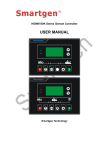
HAT260 ATS (Automatic Transfer Switch) Controller USER MANUAL Smartgen Technology CONTENT 1 OVERVIEW ........................................................................................................... 4 2 PERFORMANCE AND CHARACTERISTICS ....................................................... 4 3 SPECIFICATION ................................................................................................... 5 4 PANEL DESCRIPTION ......................................................................................... 6 5 PANEL OPERATION AND CONNECTIONS ......................................................... 6 5.1 5.2 Delay Adjustment ............................................................................................ 6 Control Setting ................................................................................................ 6 6 TERMINALS DESCRIPTION ................................................................................ 9 7 TYPICAL APPLICATION ..................................................................................... 10 8 CASE DIMENSIONS ........................................................................................... 12 9 FAULT FINDING.................................................................................................. 13 1 OVERVIEW HAT260A ATS controller using microprocessor as its core can precisely monitor 2-way 3 phase voltage, make accurate judgment on abnormal voltage (loss of power, over voltage, under voltage, loss of phase) and control ATS to transfer after delay. When #1 power is abnormal, the controller will send signal to start genset. HAT270A controller is suitable for controlling SOCOMEC VS, VE, ATyS model and other ATS switches of similar function. 2 PERFORMANCE AND CHARACTERISTICS HAT260A controller can monitor 2-way 3 phase voltage (2 way mains or 2 way generator, or 1 way mains and 1 way generator) and control ATS to transfer. Its performance and characteristics are shown as below: The controller is power supplied by A phase and N phase of #I and #II or DC (8V~35V). The normal delay of #I or #II power supply can be set within (0~60) seconds. Genset start delay can be set within (0~60) seconds. The abnormal delay of #I or #II power supply can be set within (0~60) seconds. Genset stop delay can be set within (0~60) seconds. “#I priority”, “Auto/Manual”, “No priority” and “#II priority” can be set via controller front panel; Isolated design of 2-way Neutral; ATS running status can be shown clearly with the help of LED which mounted on front panel With dual power supply conversion circuit, LO and NO output (5A AC230V) can be applied directly as the power supply for ATS; The output contactor capacity of Genset start relay (GENS START) is 3A 28VDC, active contact. Output GND is active. Controller has strong ability of anti-electromagnetic interference, can be used under complex electromagnetic interference environment; Modular construction design, flame-resisting ABS plastic shell, pluggable terminals connection with compact structure and easy installation. 3 SPECIFICATION ♦ Power supply input AC power supply: AC230V±30% (50 Hz/60Hz) (from A phase and N phase of #I and #II) DC power supply: DC(8~35)V between VIN and GND Measured voltage: rated line voltage 400V; 50 Hz/60Hz; 3 phase 4 wire. NOTE: Other measured voltage class, please consult before ordering. ♦ Range of abnormal power Over Voltage threshold: 240~290V, ±5V; Default: 265±5V. Under Voltage threshold: 164~198V, ±5V; Default: 172±5V ♦ Action time Closing time: 5 seconds. During this period, if detected close signal is active, immediately disconnect. Opening time: 3 seconds. During this period, if detected close signal is active, immediately disconnect. Voltage normal delay: (1~60) seconds (adjusted via panel potentiometer). Voltage abnormal delay: (1~60) seconds, default: 5 seconds (adjusted via panel potentiometer). Genset start delay: when #I abnormal is confirmed, delay within (1~60) seconds, default: 5 seconds (adjusted via panel button) Genset stop delay: when #I normal is confirmed, delay within (1~60) seconds, default: 60 seconds (adjusted via panel button). ♦ #I/#II closing monitoring (can be programmed via panel button) Default: detect #I/#II closing status, and the controller closing status signal must be active. ♦ Power consumption When module is in rated voltage, power consumption of voltage circuit is not more than 2VA. ♦ Environment conditions Working Temperature: (-30~+70)ºC ♦ Weight Net weight: 0.47Kg Humidity: (20~95)%RH 4 PANEL DESCRIPTION 5 PANEL OPERATION 5.1 Delay Adjustment #I normal delay potentiometer: can set output delay after #I power supply normal. #II normal delay potentiometer: can set output delay after #II power supply normal. 5.2 Control Setting a) Auto Mode: Press will extinguished. , automatic indicator will light while manual indicator When controller is in auto mode, the corresponding indicator will light. The ATS will “Close” or “Open” according to the status of #I and #II power supply; it will transfer according to the pre-set priority if #I and #II are both normal. If there is no priority, the engine will be drove by power supply which is reach normal status earlier; in addition, the power supply will working uninterrupted until it gets abnormal and transferred to the other power supply automatically. b) Manual Mode: Press will extinguished. , automatic indicator will light while manual indicator button: In Manual mode, press key, load will be transferred to #I power supply. It is invalid in auto mode. *1 button: In Manual mode, press the button will disconnect the power supply. It is invalid in auto mode. (the button is invalid for SOCOMEC VS ) button: In Manual mode, press *1 key, load will be transferred to #II power supply. It is invalid in auto mode. *1 button: pressing it can set the controller as Auto mode or Manual mode Pressing and holding it for more than 3s can test all LED indicator. 1 2 *1 NOTE: When the controller is NOT detect closing status, then, users need to choose which circuit will take load in the manual mode. (When use SOCOMEC VS ) #I/#II indicators will extinguish simultaneous after press “open” button by manual. c) #I/#II Voltage Abnormal Delay, Start/Stop Delay, #I/#II Power Priority And Closing Status Detection and Firstly, disconnect the power supply, pressing and holding key simultaneously; then connect the power supply, #I power indicator, automatic status indicator and #II power indicator are flashing, which means the controller can be set. The setting procedures are as below: Pressing can circularly select the setting items. Different items have corresponding flashing LED indicators on the panel. The setting the item as below: Items LED Description Confirmation After #I/#II Power abnormal delay #I power indicator flashes adjusting “#I normal delay” #I power potentiometer, press key, #I power abnormal indicator illuminates, which means the delay setting is saved. Set range: (0~60)s After adjusting “#I normal delay” #II power potentiometer, press abnormal indicator illuminates, delay the setting is saved. Set range: (0~60)s key, #I power which means Press key, #I power indicator Restore illuminates, which means the default factory default value is restored. Abnormal delay of #I and #II power supply is 5s by default. After adjusting “#I normal delay” Start delay Start/Stop delay Automatic status indicator flashes Stop delay potentiometer, press status indicator illuminates, means the setting is saved. Set range: (0~60)s After adjusting “#II normal potentiometer, #I/#II power priority(*1) #II power indicator flashes key, automatic status key, # II power supply key, #II power supply indicator illuminates, and then #II power supply is main power to supply for the load. Press No priority key, indicator illuminates, and then #I power supply is main power to supply for the load. Press #II priority delay” indicator illuminates, means the default value is restored. Default : Start delay is 5s and stop delay is 60s. Press #I priority press which automatic status indicator illuminates, which means the setting is saved. Set range: (0~60)s Press Restore factory value key, automatic key, #II power supply indicator illuminates; which means there is no priority supply for the load between #I and #II power supply. Closing #I closing key, #I closing Indicator Not detect Press status of Indicator #I/#II closing status illuminates; which means detection of flashes #I and #II closing input is disabled. power (*2) HAT260 ATS Control Module key, #I closing Indicator Detect closing Press status illuminates; which means detection of #I and #II closing input is enabled. *1 Note: Once the controller is powered on, its priority can be judged by the following three conditions. If #I power supply indicator flashes rapidly for three times, indicating #I power supply for priority transfer. If #II power supply indicator flashes rapidly for three times, indicating #II power supply for priority transfer. If #I and #II power supply indicators flash simultaneously for three times, indicating there is no priority transfer. *2 Note: Once the controller is power on, if #I and #II power supply indicators flash simultaneously, means #I and #II closing detection is enabled; if not, the detection is disabled. Detect enabled: #I and #II closing status is judged by input status. Detect disabled: #I and #II closing status is judged by closing/opening action and closing input port is deactivate. 6 TERMINALS DESCRIPTION ♦ Terminals A1, B1, C1 and N1: Separately connect A, B, C and N of #I power. ♦ Terminals A2, B2, C2 and N2: Separately connect A, B, C and N of #II power. ♦ Terminal S1: Closing status input of #I power supply (passive contact input, connect to GND is active) ♦ Terminal S2: Closing status input of #II power supply (passive contact input, connect to GND is active) ♦ Terminal FO(FORCE OPEN):Connect to GND is active. When the input is active, whether in manual mode or automatic mode, ATS will be switched to OFF position, both manual and automatic operations are disable. Forced Open is activated only for switches with OFF position like SOCOMEC VE type, ATyS3 type, etc. but SOCOMEC VS type is invalid. ♦ Terminal VIN, GND: DC power supply. ♦ Terminal GS (GNESET START): Genset start relay (active contactor, capacity: 3A, Output GND is active.) ♦ Terminal LO, NO: It is the power supply for ATS. LO/NO separately comes from A and N phase of #I and #II power. When A phase and N phase of #I or #II power is normal, the two terminals will output power (capacity is AC5A/230V). ♦ ♦ ♦ ♦ Terminal COM: SOCOMEC ATS closing and opening control. Terminal O: SOCOMEC ATS opening control (contact capacity is AC3A/230V). Terminal I: SOCOMEC #I closing control (contact capacity is AC3A/250V). Terminal II: SOCOMEC #II closing control (contactor capacity is AC3A/250V). 7 TYPICAL APPLICATION SOCOMEC VE Type Switch SOCOMEC VS Type Switch SOCOMEC ATySM3s Type Switch SOCOMEC ATyS3e Type Switch HAT260 ATS Control Module SOCOMEC ATyS3s Type Switch Note: 81, 84: #I closing N/O auxiliary contact of ATyS3s switch; 91, 94: #II closing N/O auxiliary contact of ATyS3s switch; The SOCOMEC ATyS3s switch has not marked the closing auxiliary contact. Please refer to the wiring diagram for the specific position. 8 CASE DIMENSIONS 9 FAULT FINDING Symptoms Controller inoperative Switch is not activated #I or #II normal indicator flashes. In Auto mode, # I or # II normal indicator illuminates but cannot transfer. Failed to start Possible remedy Check DC power supply; Check connections of #I and #II power; Check the fuse of #I and #II power. Check ATS mechanism. Check the connection between ATS and controller. Check if 3-phase voltage is normal.(over/under voltage, loss of phase, including loss of neutral line) Set the controller as Manual Mode and see if it can switch. Check voltage normal delay, shorten the delay time. Check the connection between ATS and controller. Only when #I voltage is abnormal, controller will send start signal. Check the voltage between VIN and GND is normal or not. Check start delay, shorten the delay time.