1
Chapter 3
Plan and Configure a Fieldbus System
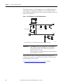
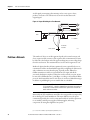
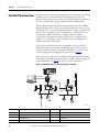
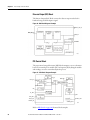
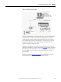
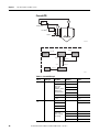
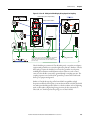
The example shows the 1757-FFLD linking device communicating with a
Smar FI 302 temperature transmitter and a Smar LD 292 pressure transmitter
to send and receive data from the Logix controller.
Therefore, RSFieldbus software and RSLogix 5000 programming software must
be installed on your host computer to initiate and maintain FOUNDATION
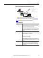
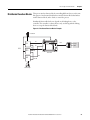
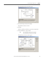
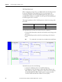
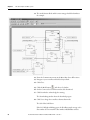
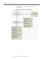
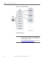
Fieldbus projects. Figure 23 shows an example of a function block in
RSLogix 5000 software followed by a control strategy in RSFieldbus software.
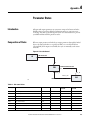
Figure 23 - Project Example
PV
ControlLogix
SP
P-10 PIC
1-10
OP
Steam
V-3
Steam Drum
PT
1-11
E-2
P-9
P-8
OUT = 904.98608
LD292 AI
OUT_O = 23
FFLD LGX
IN_O = 904.98608
FI302 AO
CAS_IN =23
BKCAL_OUT = 23
45154
SP stands for setpoint; the target value for the AI function block. See page 44.
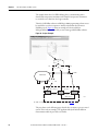
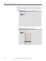
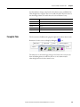
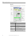
The procedures on the following pages describe how to initiate a process control
system. This is only an example; your application likely will include different
instrumentation but the procedures are similar.
56
Rockwell Automation Publication RSFBUS-RM001A-EN-P - June 2011