1
X412-824-864 / c24/64plus expandable alarm control unit with 12/64 inputs www.amcelettronica.com 1 installer's manual X - C seriesV1.0 INDEX DESCRIPTION............................................................................................................................. 5 Contents of the package.................................................................................................. 6 assembly Kit............................................................................................................................ 6 programming menu from keyboard - 1........................................................................ 8 programming menu from keyboard - 2........................................................................ 9 programming menu from keyboard - 3........................................................................ 10 programming menu from keyboard - 4........................................................................ 11 programming menu from keyboard - 5........................................................................ 12 programming menu from keyboard - 6........................................................................ 13 programming menu from keyboard - 7........................................................................ 14 user programming menu 1................................................................................................ 15 user programming menu 2................................................................................................ 16 REMOTE VOCAL MANAGEMENT MENU................................................................................... 17 description of the electronic board OF C SERIES - connections................... 18 terminals................................................................................................................................. 18 description of the electronic board OF X SERIES - connections................... 19 terminals................................................................................................................................. 19 connections - serial bus................................................................................................... 20 connections - sirens.......................................................................................................... 20 connections - outputs....................................................................................................... 20 connections - loads............................................................................................................ 22 connections - zone terminals........................................................................................ 22 connections - PHONE terminals..................................................................................... 23 coNNECTIONS - PSTN TELEPHONE LINE (ONLY X SERIES)................................................ 24 connections - battery terminals.................................................................................. 24 connections - general electronic board supply terminals............................ 24 tamper switch key................................................................................................................ 24 SIM card slot.......................................................................................................................... 24 rec key...................................................................................................................................... 24 pc connector........................................................................................................................ 24 signalling LEDs...................................................................................................................... 24 antenna connector............................................................................................................. 24 peripherals that can be connected............................................................................ 25 k-lcd and k-voice terminal. ......................................................................................................................... k-radio keypads. ......................................................................................................................................... input expansions......................................................................................................................................... OUTPUT expansions.................................................................................................................................. expr/s radio expansion................................................................................................................................ readers (remote sockets)........................................................................................................................... First start up......................................................................................................................... LED functioning logic........................................................................................................ starting reset....................................................................................................................... disarm keypad status.......................................................................................................... Programming (from keyboard)....................................................................................... enter programming move to the menu.......................................................................................................... 25 25 26 26 27 27 29 29 29 29 30 30 PERIPHERALS menu................................................................................................................. 30 menu of TELEPHONE NUMBERS........................................................................................... 31 system events menu............................................................................................................ 32 assign the phone numbers........................................................................................................................... 32 Change system event recordings................................................................................................................ 33 menu of INPUTS....................................................................................................................... 34 www.amcelettronica.com 2 X - C seriesV1.0 INPUTS: NAME............................................................................................................................ INPUTS: TYPE............................................................................................................................. MENU of inputs: FUNCTION..................................................................................................................... MENU of inputs: state............................................................................................................................... MENU of inputs: alarm pulses................................................................................................................... MENU of inputs: programs ON/OFF.......................................................................................................... MENU of inputs: users ON/OFF................................................................................................................ MENU of inputs: lock exclusion. ............................................................................................................... MENU of inputs: test enabling................................................................................................................... MENU of inputs: keypad buzzer.................................................................................................................. MENU of inputs: sirens activation. ............................................................................................................ MENU of inputs: Autoexclusion................................................................................................................. MENU of inputs: zones delays................................................................................................................... MENU of inputs: telephones link................................................................................................................ 34 36 37 38 38 38 38 39 39 39 40 40 40 41 OUTPUTS: NAMES..................................................................................................................... MENU of outputs: FUNCTION.................................................................................................................. MENU of outputs: duration....................................................................................................................... MENU of outputs: delay............................................................................................................................ MENU of outputs: polarity........................................................................................................................ MENU of outputs: autoreset..................................................................................................................... MENU of outputs: OPERATING CONDITIONS........................................................................................ MENU of outputs: telephones link............................................................................................................. MENU of outputs: users link..................................................................................................................... MENU of outputs: inputs link.................................................................................................................... 42 44 45 45 45 45 46 46 46 47 menu of menu of menu of OUTPUTS................................................................................................................... 42 menu of wireless menu....................................................................................................................... 48 Wireless menu: device self-learning........................................................................................................... 48 Wireless MENU: EXpr reset..................................................................................................................... 49 Wireless MENU: rssi................................................................................................................................. 49 programs menu..................................................................................................................... 50 programs menu: Partials NAMES............................................................................................................... 50 programs menu: partial zones (assigning inputs to partials)........................................................................ 50 programs menu: exit times........................................................................................................................... 50 groups menu.......................................................................................................................... 51 groups menu: NAMES................................................................................................................................ 51 --> prog. (associate partials to groups).................................................................... 51 groups menu: groups PSTN MENU................................................................................................................................ 52 ademco - tone amplitude (dtmf) - pstn......................................................................................................... 52 arming lock menu................................................................................................................. 53 timerS menu............................................................................................................................. 54 timerS menu: setting................................................................................................................................... 54 . ........................................................................................................................... 55 timerS menu: eNABLE exclusions............................................................................................................... 55 timerS menu: exclusions menu users.............................................................................................................................. 56 menu users: uSER nAMES......................................................................................................................... 56 Type. ............................................................................................................................. 56 menu users: programs linking..................................................................................................................... 56 use of user 32 and/or 64............................................................................................................................ 56 menu users: users date/hour menu..................................................................................................................... events menu............................................................................................................................ SYSTEM reset menu.............................................................................................................. ADEMCO menu.......................................................................................................................... 57 57 58 59 CID EVENTS............................................................................................................................................. 59 link phones cid. .......................................................................................................................................... 59 4+2 events................................................................................................................................................. 60 link phones 4+2.......................................................................................................................................... 60 ademco - phone numbers. ............................................................................................................................ 60 www.amcelettronica.com X - C seriesV1.0 3 - system id...................................................................................................................................... - max attempts................................................................................................................................ ademco - waiting reply................................................................................................................................ ademco - zones recovery............................................................................................................................ ademco - tone amplitude (dtmf) gsm. ........................................................................................................... ademco ademco 61 61 61 61 61 test menu................................................................................................................................. 62 menu other parameters.................................................................................................... 63 other parameters: siren settings................................................................................ 63 siren settings: siren pause.......................................................................................................................... 63 63 .................................................................................................................... 63 siren settings: siren duration..................................................................................................................... siren settings: siren cycles other parameters: tamper settings............................................................................ 63 tamper settings: system tamper. ................................................................................................................. 63 tamper settings: Tamper ap......................................................................................................................... 63 tamper settings: Tamper ap Type................................................................................................................. 63 tamper settings: tamper peripherals........................................................................................................... 63 other parameters: dialer settings.............................................................................. 64 dialer settings: rings numbers.................................................................................................................... 64 64 dialer settings: accept calls...................................................................................................................... 64 dialer settings: enable Ring. ...................................................................................................................... 64 dialer settings: events delay...................................................................................................................... other parameters: radio settings............................................................................... 64 radio settings: learn.................................................................................................................................. 64 ......................................................................................................................... 64 radio settings: radio noise.......................................................................................................................... 64 radio settings: saturation other parameters: EN50131 settings........................................................................... 65 EN50131 settings: enable 50131............................................................................................................... EN50131 settings: visual.status................................................................................................................ EN50131 settings: visual.zones/troubles. ................................................................................................. EN50131 settings: no 220 (min)................................................................................................................. EN50131 settings EN 50131: self-exclusion............................................................................................. other PARAMETERS: life test ............................................................................................................... other PARAMETERS: quick arming........................................................................................................... other PARAMETERS: speakerphone......................................................................................................... other PARAMETERS: maintenance. .......................................................................................................... 65 65 65 65 65 65 65 65 66 programming keys............................................................................................................... 66 technical specifications................................................................................................... 66 warranty................................................................................................................................. 67 www.amcelettronica.com 4 X - C seriesV1.0 english DESCRIPTION C - X series are 4/8 inputs control unit that can be expanded to 12/40/64 inputs with a built-in PSTN and/or GSM telephone line dialer that can make VOICE calls, send SMS and digital protocols. They have a voice synthesizer system which can keep you informed on the system status either locally using a keypad equipped with a speaker or remotely through a PSTN and/or GSM telephone line. You can also have the plug-in GSM module for the X series or the GSM integrated module for the C series and select the priority of calls and text messages and protocols. NOTE: the C series has only the GSM dialer and not the PSTN NOTE: the X series has only the PSTN dialer and the optional plug-in GSM Programming can be done through the local keypad or with PC software. Its main features are: FEATURES inputs outputs users partials groups keypads plugs wireless zones wireless expansions input expansions output epansions telephone numbers PSTN GSM siren output relè auxiliary output relè PC software IP management X412 4 -12 5 16 4 4 4 4 4 -12 1 1 8+8 si si optional X840 8 - 40 5 -11 32 8 4 8 8 8 - 40 2 4 2 8+8 si si optional X864 8 - 64 5 - 17 64 8 4 8 8 8 - 64 2 7 4 8+8 si si optional C24PLUS 8 - 24 5-8 32 4 4 4 4 8 - 24 1 2 1 8+8 no si C64PLUS 8 - 64 5 - 17 64 8 4 8 8 8 - 64 2 7 4 8+8 no si si no si si si si si si si si si si si si si si si si si si www.amcelettronica.com 5 X - C seriesV1.0 Contents of the package assembly Kit V2 screw Fastening Power Supply Assemble Product Power supply control unit Control Unit Tamper Spring Mains supply Cables Battery supply V2 screw Fastening Power Supply Trimmer Label "E2" product Cable yellow/green "YG" T YG R4 V2 M R3 E2 Rm V1 V8 E1 www.amcelettronica.com R Photo 2 Parts in the assembly Kit Photo 1 6 X - C seriesV1.0 Power supply fastening holes V2 screws Photo 3 Central Turret fastening GROUND BLACK RED E2 product label Photo 4 Photo 5 Photo 6 Photo 8 Photo 7 Photo 9 • Attach the power supply on the bottom of the box, holes F1- F2, using 2 type V2 screws (photo 1, photo 2). The screws are attached on the power supply side. • Attach the 4 metal Control Unit support turrets T (photo 2 - photo 7) in holes F3 *- F4* - F5* - F6* (photo 5) using 4 type V8 screws (photo 2). Between the turrets and the bottom of the box, attach the metal washer V8 * = in place of the holes, you may find the boxes ready for threaded pins. In this case, screw the turrets on the pins and don't use the metal washers or the 4 mounting screws. • Attach the Control Unit Tamper Spring M as shown in photo 6. • Attach the label with the serial number (part of the metal label, E1, photo 2), below the board in the position indicated in photo 3. • Attach the Control Unit board to the 4 turrets and lock it in place with the remaining 4 type V8 screws (photo 1 - photo 7). • Wire the red and black wires from the power supply to the control unit according to the proper polarity. See photo 4 • Apply the part of the product identification label E2 (photo 2) in the position shown in photo 5. • Connect the Yellow/Green wire to the bottom of the case after having removed the protection on the attachment terminal. The other end of the cable is connected to the metal cover. • When all the electrical connections have been made and the Control Unit is receiving power, MAKE SURE the board voltage value (measured on the Power Supply Terminal Photo 4) is 14.2 V. Otherwise, adjust the power supply trimmer (photo 1 Trimmer) until it reaches 14.2 V. • When the operation is complete, mount the closing cover after having assembled the mounting screw, V1 screw + 4 mm. washer. R4 + 2 mm washer. R2 (photo2 - photo8 - photo9) Use the resistors R for any input balancing needs: Brown, Black, Red resistors = 1Kohm Red, Red, Red resistors = 2.2Kohm www.amcelettronica.com 7 X - C seriesV1.0 programming menu from keyboard - 1 PERSONAL CODE MENU PERIPHERALS Keypad 12345678 ON/OFF □●●●●●●● Keypads Keypad 01 SOUND Inputs expansions Expansion 12345678 ON/OFF □●●●●●●● Outputs expansions Expansion 12345678 ON/OFF □●●●●●●● Wireless expansions Expansion 12345678 ON/OFF □●●●●●●● GSM module Enable GSM 0 Plug 12345678 ON/OFF □●●●●●●● Plugs Plug 01 SOUND Programs Plugs 1 MENU TEL.NUMBERS K<>A □●●● K<>A □●●● Prg. LED1 12345678 □●●●□●● Prg. LED4 12345678 □●●●□●● TEL. NUMBER [01] TEL.OPTIONS ABC Tel.01 □●● Attempts Time 15 Waiting Reply 50 Attempts Number Mex.Repetition 3 2 Calls Reset 999999 Tel Prog. MENU SYSTEM EVENTS 12345678 ●●●●●●●● SYSTEM EVENTS Link Phone Numbers SYSTEM EVENTS Play/Record www.amcelettronica.com M1 = AC Line OFF M2 = AC Line ON M3 = Low Battery M4 = Life Test M5 = GSM OFF 1min M6 = Tamper M7 = RF Noise M8 = RF Saturat. M9 = RF Battery M10 = No Supervis. M11 = RF Tamper M12 = User Disabled M13 = System Lock M14 = Coercion M15 = Tel.LineFail M16 = Tel.Line OK M17 = Opening Tecno M18 = System Name Credit Echo 8 Mxx/Tel *-Play Mxx*-Play 12345678 V-S-T - - - X-Rec X - C seriesV1.0 programming menu from keyboard - 2 MENU INPUTS INPUTS MENU Name I01-Input 01 *-Play INPUTS MENU Type [01] input one CCCCCCCC----------- INPUTS MENU Function [01] input one AAAAAAAA------------ INPUTS MENU State [01] input one □□□□□□□□●●●●●●● INPUTS MENU Alarm Pulses [01] input one INPUTS MENU Programs On/Off V-Edit 1 I01/Prg 12345678 Input one ●●●●●●● INPUTS MENU Users On/Off [01] input one User INPUTS MENU Lock Exclusion [01] input one ●●●●●●●●●●●●●●● INPUTS MENU Test Enabling [01] input one ●●●●●●●●●●●●●●● INPUTS MENU Keypad Buzzer [01] input one ●●●●●●●●●●●●●●● INPUTS MENU Sirens Activat. [01] input one 22222222222222222 INPUTS MENU Zones Delays [01] input one INPUTS MENU AutoExclusion [01] input one ●●●●●●●●●●●●●●● INPUTS MENU Telephones Link. www.amcelettronica.com I01-Input 01 076 179 000 000 I01/Tel *-Play 1 30 12345678 V-V- - - - - 9 X - C seriesV1.0 programming menu from keyboard - 3 MENU OUTPUTS MENU WIRELESS MENU OUTPUTS Names U01-Output Nr 01 *-Play V-Edit U01-Output Nr 01 180 179 000 000 MENU OUTPUTS Function [01] output one XVBNA--- MENU OUTPUTS Durations [01] output one 00 h 00 min 00 MENU OUTPUTS Delay [01] output one 00 h 00 min 00 MENU OUTPUTS Polarity [01] output one 00000000 MENU OUTPUTS Auto Reset [01] output one 00000000 MENU OUTPUTS Operating Cond. [01] output one XXXXXXXX MENU OUTPUTS Telephones Link. O01/Tel 12345678 output one ●●●●●●● MENU OUTPUTS Users Link O01- User Nr 01 ●●●●●●●●●●●●●●● MENU OUTPUTS Inputs Link O01- Input one ●●●●●●●●●●●●●●● WIRELESS EXPR1 Storing EXPR1 Waiting … Free 10 / 32 D01-CU400 Nr.01 Signal WIRELESS EXPR2 Storing EXPR2 Waiting … Free 32 / 32 D01-CU400 Nr.01 Battery 70% WIRELESS EXPR1 Reset EXPR1 RESET??? Free 10 / 32 D01-CU400 Nr.01 Input □□● WIRELESS EXPR2 Reset EXPR2 RESET??? Free 32 / 32 D01-CU400 Nr.01 Superv. (Min) 60 WIRELESS EXPR1 RSSI 50% D01-CU400 Nr.01 REED In 0 WIRELESS EXPR2 RSSI 0% D01-CU400 Nr.01 EXT In 0 D01-CU400 Nr.01 SWITCH In 0 D01-CU400 Nr.01 Replacing D01-CU400 Nr.01 Erasing MENU PROGRAMS MENU PROGRAMS Partials Names P01-Program Nr01 *-Play V-Edit MENU PROGRAMS Partial 1 Zones [01] input one □□□□□□□□●●●●●●● MENU PROGRAMS Exit Times [01] program 1 [Sec] www.amcelettronica.com P01-Program Nr01 106 000 000 000 30 10 X - C seriesV1.0 programming menu from keyboard - 4 MENU GROUPS MENU PSTN MENU GROUPS Names G01- Group 01 *-Play V-Edit MENU GROUPS Groups Prog. G01/Prg total 1 Voice Call ONLY PSTN PSTN DialTone Check 1 Ademco Call ONLY PSTN PSTN RingBack Check 1 4.0 PSTN SkipAnsw.Mach. PSTN Dtmf On PSTN MENU ARMING LOCK 1234 □□□□ PSTN Line Check PSTN Ring Pause G01- Group 01 176 000 000 000 0 50 ARMING LOCK No220V 0 ARMING LOCK Battery 0 ARMING LOCK Tamper 0 ARMING LOCK LineTamper 0 ARMING LOCK Periph.Tamper 0 ARMING LOCK NoGsm 0 ARMING LOCK NoPstn 0 MENU TIMERS TIMERS Setting Day Day TIMERS Exclusion TIMERS Enable Exclusion www.amcelettronica.com TIMERS TIMERS [Sun] [Sat] Period 01 00/00 00/00 Period 08 00/00 00/00 T01-Sun 12345678 ●●●●●●●● T04-Sat 12345678 ●●●●●●●● 11 Timer 01 – Sun hr 00:00 min Timer 04 – Sun hr 00:00 min Timer 01 – Sun PROGRAMS Prg. program 1 1234 ---- Timer 01 – Sun OUTPUTS [01] output one -------- Timer 01 – Sun USERS [01] User Nr 01 ---------------- X - C seriesV1.0 programming menu from keyboard - 5 MENU USERS USERS Users Names USERS Users Type USERS Codes Setting User Num. User Nr 01 [01] [01] User Nr 01 M Technician Code 000000 Telemanag. Code 777777 CODE:User Nr 01 111111 USERS Programs Linking U01/Prg User Nr 01 1234 □□□□ USERS Groups Linking U01/Group User Nr 01 1234 □□□□ MENU DATE/HOUR Sun 01/01/00 08:00:00 MENU EVENTS EVENTS MEMORY All EVENTS MEMORY Unread EVENTS MEMORY Alarms EVENTS MEMORY Anomalies EVENTS MEMORY Arming/Disarming EVENTS MEMORY Users MENU SYSTEM RESET SYSTEM RESET Users Codes Reset Ongoing Wait... Reset Completed # Exit SYSTEM RESET Configuration Reset Ongoing Wait... Reset Completed # Exit SYSTEM RESET Events Memory www.amcelettronica.com Autorization [ ] 12 Reset Ongoing Wait... Reset Completed # Exit X - C seriesV1.0 programming menu from keyboard - 6 MENU ADEMCO ADEMCO CID Events ADEMCO Link Phones CID A01/Tel *-View ADEMCO 4 + 2 Events ADEMCO Link Phones 4+2 Phones 4+2 ADEMCO Phone Numbers 12345678 ●●●●●●●● TEL.NUMBER [01] 12345678 ●●●●●●●● A1 SIREN 320 ZONE TAMPER ARM. BY USER 01 [10] A2 DISAR.BY USER 01 [20] A3 ZONE ALARM 01 [30] A4 ZONE RECOVERY 01 A5 ZONE BYPASS 01 [50] A6 SYSTEM ON/OFF 401 AC MISSING [60] A7 REMOTE ON/OFF 407 AC RECOVERY [61] A8 ON/OFF BY TIMER 403 LOW BATTERY [62] A9 RECOVERY BATTERY A10 TAMPER [64] A11 WIR.DEV.LOW BAT. 384 TAMPER RECOVERY A12 WIREL.NO SUPER. 381 REMOTE ARMING [66] A13 WIRELESS TAMPER 383 REMOTE DISARMING A14 PERIPH.TAMPER 341 ROBBERY [68] A15 LIFETEST [00] A16 ARMED BY PRS [70] A17 DISARMED BY PRS [80] A18 AUTOARM.FAILED [90] A19 PANIC [A0] A20 PANIC RECOVERY [B0] A21 137 NO 220V 301 LOW BATTERY 309 NO GSM LINE 351 [40] ADEMCO System ID ADEMCO Max Attempts ADEMCO Waiting Reply ADEMCO Zone Recovery Tel 01/ID CODE 1234 3 15 1 LIFE TEST 602 RF NOISE 344 [63] ADEMCO Delay Recovery 0 ADEMCO Dtmf On GSM 40 ADEMCO Dtmf On PSTN [65] 50 [67] SYSTEM RESTART 305 WRONG CODE 461 ZONES EXCLUSION 570 COERCION SILENT PANIC TECNO INPUT 121 120 150 EVENT LOG RESET 621 A23 GENERAL RESET 313 A25 A87 13 627 A22 A24 www.amcelettronica.com PROG.MODE ENTRY PHONE LINE [01] input one [64] input six four 352 130 130 X - C seriesV1.0 programming menu from keyboard - 7 MENU TEST TEST Siren SIREN TEST Activate?? SIREN TEST Disactivate?? TEST Inputs INPUTS TEST Tot:08 V-Stop INPUTS TEST 01-input one TEST Outputs TEST OUTPUTS Tot:05 V-Start 01-output one Activate?? TEST VoiceCall PSTN TEST VoiceCall GSM TEST ContactID PSTN TEST ContactID GSM TEST Ademco4+2 PSTN TEST Ademco4+2 GSM MENU OTHER PARAMETERS OTHER PARAMETERS Siren Settings OTHER PARAMETERS Siren Pause 15 OTHER PARAMETERS Siren Durat. 45 OTHER PARAMETERS Siren Cycles OTHER PARAMETERS Tamper Settings 0 OTHER PARAMETERS System Tamper 0 OTHER PARAMETERS OTHER PARAMETERS Tamper AP EN50131 Settings OTHER PARAMETERS Enable EN50131 0 0 OTHER PARAMETERS Visual.Status OTHER PARAMETERS 1 Tamper AP Type NC OTHER PARAMETERS OTHER PARAMETERS Visual.zones OTHER PARAMETERS No220 (min) Tamper Periph. 1 1 OTHER PARAMETERS OTHER PARAMETERS Dialer Settings Rings Number 0 3 OTHER PARAMETERS OTHER PARAMETERS Events Delay Life Test 0 OTHER PARAMETERS Self-Excl. 3 5 OTHER PARAMETERS OTHER PARAMETERS Radio Setting OTHER PARAMETERS Learn Speakerphone 1 1 OTHER PARAMETERS OTHER PARAMETERS Radio Noise Quick Arming 0 1 OTHER PARAMETERS OTHER PARAMETERS Saturation www.amcelettronica.com Maintenance 1 1 14 X - C seriesV1.0 user programming menu 1 PERSONAL CODE ARM SYSTEM Use the number keys to select the partials 2 4 5 6 7 8 9 0 program 1 1------- Arming single Program, confirm with Enter 0=TOT 1-8=PRG -------- Use the joistik to arm the groups perimetric 12-----up EVENTS MEMORY All Arming group Perimeter, sum of the program 1 and 2 dx sx MENU EVENTS 3 1 down EVENTS MEMORY Unread EVENTS MEMORY Alarms ATTENTION : a non MASTER user, when enter his menu can ONLY: EVENTS MEMORY Anomalies - PROGRAM KEYS - ERASE KEYS EVENTS MEMORY Arming/Disarming EVENTS MEMORY Users Use the joistik to select and activate the outputs ACTIVATE OUTPUTS [01] output one EDDDE-------- Keys sx and dx for outputs selection Keys up and down for activate and deactivate D = Deactivate E = Activate up dx sx down ENABLE TELEMANAGEMENT CHANGE CODE TELEMANAGEMENT Enabled 0 CODE: User Nr 01 111111 CODE: User Nr 32 ------ PROGRAMMING KEYS PROGRAM KEYS User Nr 01 Press ENTER PROGRAM KEYS User Nr 32 DELETE KEYS DELETE KEYS User Nr 01 Press ENTER DELETE KEYS User Nr 32 www.amcelettronica.com 15 Insert Key by 15 sec. Deleting Key Success! # Exit X - C seriesV1.0 user programming menu 2 CREDIT MANAGEMENT Tel. TIM 40916 Tel. VODAFONE 404 Tel. WIND 4155 Tel. OTHER Sms. TIM PRE CRE SIN Sms. VODAFONE Sms. WIND SALDO Sms. OTHER KEYWORD Credit Threshold [Euro] 3 VOLUME SETTING Level VOLUME 2 OTHER PARAMETERS Speakerphone MENU TEST TEST Siren 1 SIREN TEST Activate?? SIREN TEST Disactivate?? TEST Inputs INPUTS TEST Tot:08 V-Stop INPUTS TEST 01-input one TEST Outputs TEST OUTPUTS Tot:05 V-Start 01-output one Activate?? TEST VoiceCall PSTN TEST VoiceCall GSM TEST ContactID PSTN TEST ContactID GSM TEST Ademco4+2 PSTN TEST Ademco4+2 GSM MENU DATE/HOUR Sun 01/01/00 08:00:00 www.amcelettronica.com 16 X - C seriesV1.0 REMOTE VOCAL MANAGEMENT MENU SELECT 1 TO ACT ON THE DIAL PERSONAL CODE PROGRAMS 1 SYSTEM DISARMED SELECT 9 TO ARM PROGRAM 1 DISARMED SELECT 1 TO ARM PROGRAM 8 DISARMED SELECT 8 TO ARM THERE ARE NOT READY ZONES INPUT 3 SELECT 1 TO EXCLUDE 2 TO INCLUDE 2 TO ACT ON THE REMOTE CONTROLS 2 OUTPUT 1 DISABLED SELECT 1 TO ACTIVATE ACTIVATION OUTPUT 1 DONE 3 TO KNOW THE STATUS OF THE INPUTS 3 ALL THE ZONES ARE CLOSED THERE ARE NOT READY ZONES www.amcelettronica.com 17 INPUT 3 X - C seriesV1.0 description of the electronic board OF C SERIES - connections UNLOCK VOICE TERMINAL terminals battery + - SIREN + - SIREN +C SIREN +PZ SIREN AP ALARM (nc - no - com) + A B - (rs 485) in 1-2-3-4-5-6-7-8 com Loads (+ -) phone out 1 OUT = 2-3-4-5-6-7-8 + REC KEY TAMPER KEY = terminals for the backup battery = power supply for the internal/external siren = operating positive missing for external siren = operating positive to give for the internal siren = line tamper - anti-opening with negative reference = free exchange relay for alarm operation = peripheral connection = inputs (NC - NA - Balanced - Double Balanced) = negative reference for the inputs = 13.8Vdc power supply for external equipment = wired telephone line emulation and speaker line terminal (to use with K-lcd VOICE) = Programmable relay output (also as separate internal siren, or log) = open-collector outputs = positive reference for open-collector outputs = voice message recording key = control unit anti-opening tamper Operation of the led on board: FLASHING RED LED = battery is absent or low RED LED FIXED = if GSM is disabled, it indicates a fault on the PSTN line = if PSTN is disabled, it indicates a fault on the GSM line = if both are active, it indicates a fault on one of the 2 lines www.amcelettronica.com 18 X - C seriesV1.0 description of the electronic board OF X SERIES - connections terminals battery + - SIREN + - SIREN +C SIREN +PZ SIREN AP ALARM (nc - no - com) + A B - (rs 485) in 1-2-3-4-5-6-7-8 com Loads (+ -) SPK out 1 OUT = 2-3-4-5-6-7-8 + REC KEY TAMPER KEY L1 - L2 T1 - T2 = terminals for the backup battery = power supply for the internal/external siren = operating positive missing for external siren = operating positive to give for the internal siren = line tamper - anti-opening with negative reference = free exchange relay for alarm operation = peripheral connection = inputs (NC - NA - Balanced - Double Balanced) = negative reference for the inputs = 13.8Vdc power supply for external equipment = terminal line speakerphone (for use with K-LCD VOICE) = Programmable relay output (also as separate internal siren, or log) = open-collector outputs = positive reference for open-collector outputs = voice message recording key = control unit anti-opening tamper = telephone line output (to connect to public telephone line) = telephones output (to connect to any private telephones) Operation of the led on board: FLASHING RED LED = battery is absent or low RED LED FIXED = if GSM is disabled, it indicates a fault on the PSTN line = if PSTN is disabled, it indicates a fault on the GSM line = if both are active, it indicates a fault on one of the 2 lines www.amcelettronica.com 19 X - C seriesV1.0 connections - serial bus The peripherals (keypads, expansions, sockets, etc.) are connected to the electronic board through an RS485 line, terminals A and B. This connection complies with the generally adopted rules for this type of line. The maximum length of the entire bus section can be up to about 1000m. When cabling is done over large distances, over 400/500m, certain precautions must be taken: - It is best to use twisted cables suitable for serial lines - It is best to connect all the peripherals in cascade (with the traditional enter and exit) - avoid making too many junctions on the line - avoid making too many nodes or star connections with several branches For the use of cables that also have 2 power supply conductors for the peripherals themselves, there are no special precautions. You must keep in mind the consumption level and that the distances do not cause high voltage drops. From the peripherals you can also supply all of the sensors connected to it with no operating problems. The bus supply terminals supply 13.8Vdc - 3A protected by an independent, self-resetting fuse. If connecting supplementary power supplies, remember that the negatives must always be in common and that the technical characteristics must be identical to those provided by the manufacturer (see the technical data) The peripherals that can be connected are: - 8 keypads (two of which can be the model with the built-in radio receiver) - 8 readers (traditional type and/or transponder, or those built-into the keypads) - 2 radio type expansions - 7 input expansions (each module comes with 8 zone inputs) - 4 output expansions (each module comes with 3 O.C. outputs) note: all of the devices that can be connected START WITH ADDRESS 1 (ex. keypad 1 - socket 1 expansion 1 - expansion 2) connections - sirens The connection to the sirens is done on the SIREN terminals. AP is the terminal enabled for anti-opening protection. The reference is negative. It can be configured as NORMALLY CLOSED or as BALANCED at 1K (putting in series on the line, a resistor with that value) This parameter is found in MISC. PARAMETERS. Terminals + - are the siren power supply and battery recharge. The available current is what is provided by the power supply on the control unit. Terminal +C is the operating positive missing for siren activation. The connected siren must be configured with start at positive missing. Terminal +PZ is the command for the internal piezo siren. It supplies a positive when the system is in alarm. Terminals NC - NO - COM are free exchange alarm terminals and are done using a traditional relay. (max current 2A - 30Vdc) Note: you can also use output 1 for functions linked to the siren in order to have independent signalling of the internal siren based on the alarm zone. Or for controlling the siren flasher with separate siren/flasher commands, using a possible alarm log signal (function can be activated from the outputs menu). connections - outputs There are 5 outputs available on the control until on an expandable electronic board up to 17 with remote boards connected on the bus. All outputs, except no. 1, are the OPEN - COLLECTOR type, with a maximum current of 50mA. Output no. 1 is controlled by a traditional free exchange relay (max current 2A - 30Vdc). For connection to the O.C. outputs, the closure is negative and the current, as mentioned above, is a maximum of 50mA. It is therefore considered to be an open output when not closed/connected to negative. For relay connections or other types of low absorption loads, use a positive as reference (positive supplied on the output group terminal) or any positive that has the negative in common with the one on the control unit. You can also use the outputs with the PULL UP resistors (value 1K) to vary the reference voltages, ex. to have positives and negatives that change based on a certain programmed event. Following are a few examples of O.C. output connections: www.amcelettronica.com 20 X - C seriesV1.0 Relay reel Maximum current 50mA Pull up r 1KΩ Terminal with voltage that varies based on the output status: Out2 open = terminal with positive Out2 closed = terminal with negative www.amcelettronica.com 21 X - C seriesV1.0 connections - loads The control unit has 4 power supply terminals for external devices (2 positive and 2 negative). The voltage supplied is 13.8Vdc - 3A protected by an independent, self-resetting fuse. This terminal can supply any device connected to the control unit, with separate protection. If there are any problems on this line, the rest of the system will continue to function normally. connections - zone terminals The control unit has 8 zones (from Z1 to Z8) that can be connected using various methods, NC - NA - single BALANCING - double BALANCING The reference is negative which is represented by the 4 COM terminals located on the zone terminal board. - DOUBLE BALANCING this type of connection calls for the use of 2 single wires for signalling CUT AND SHORT CIRCUIT and ALARM The resistors used are 1K and 2K2 connected as in the diagram - SINGLE BALANCING this type of connection calls for the use of 2 single wires for signalling SHORT CIRCUIT and ALARM The resistor to use in this case is only 1K. For N.C. and N.A. connections, use the terminals by connecting them properly with the detection devices used (consult the manuals for the individual devices). The following is the diagram for connecting the zone inputs: Connection NC and NA Double balancing Single balancing Detector Tamper Alarm Detector Tamper Detector Alarm R1K Tamper R1K Alarm R2K2 Tamper line AP terminal www.amcelettronica.com 22 X - C seriesV1.0 connections - PHONE terminals The control unit has 2 terminals named PHONE, that can be used for 2 functions. - The main function is to distribute the audio on the enabled keypads. - notification of system arming and disarming - notification of open zones - notification of alarm zones The connection is done through a single terminal, which is the one closest to the output terminals (see fig.) All available keypads can be connected. The cable to be used can be any type and it is better if it is outside the serial cable for the peripheral connection. Since the audio is analogue, high impedance, it is best to use cables with sections of 0.5mm plus. Keypads with this functions have a terminal called SPK that is used for this function. You must close the EOL jumper on one of the keypads connected to the audio line. IMPORTANT: out of all of the audio keypads connected to the phone line, one MUST HAVE THE EOL JUMPER CLOSED. - The other function of these terminals is to emulate the public telephone line. You can make and receive calls, connecting a normal tone telephone on 2 terminals (see fig). IMPORTANT: this line does not have the high voltage ring notification, therefore you must program an O.C. output with RING function and connect the desired rings Audio cable Bus cable System armed/disarmed - input status - zone in alarm etc." www.amcelettronica.com 23 X - C seriesV1.0 coNNECTIONS - PSTN TELEPHONE LINE (ONLY X SERIES) Control unit has 2 terminals (L1 and L2) that can be used to connect it to the public telephone line. In case of use of telephone lines with INTERNET access is recommended to use specific filters upstream of the connection with the control unit. Terminals T1 and T2 are used to connect telephones. When control unit make a call it release the internal phones. connections - battery terminals The control unit has two buffer battery charger terminals The batteries that can be connected range from 2Ah to 17Ah. The maximum charging current is about 800mA with a voltage of 13.8Vdc. They are protected from polarity inversion and short circuits. The charging system is intelligent. It recognizes the charge applied and adjusts the current. IMPORTANT: If there are no batteries on the terminals there is no measurable voltage. The system stops delivering voltage when it does not find the battery charge. connections - general electronic board supply terminals At the supply terminals, in order to ensure proper operation, you must supply a voltage of NO LESS THAN 14.2Vdc. The current is linked to the general consumption of the connected peripherals. Refer to the technical specifications of the individual components to calculate consumptions. The control unit comes with 3A or greater power supplies tamper switch key The board is also equipped with a TAMPER key. To be used, the spring included in the package must be attached to the key itself. Afterwards, enable the protection from the related menu (misc. parameters) SIM card slot The control unit is ready to use a traditional voice SIM card. NOT DATA. Before inserting the SIM you must perform a few preliminary operations: - unlock the sim with the PIN - Delete all sms IMPORTANT: BEFORE INSERTING OR REMOVING THE SIM FROM THE SLOT, TURN THE CONTROL UNIT COMPLETELY OFF. rec key The REC key located on the board is used to start recording user identification messages. After having launched the record command from the keypad, the control unit waits. Recording starts only when the user activates the REC key that is located near the microphone. Once the message is recorded, it can be listened to immediately using the speaker on the board itself. pc connector There is a 4-pole connected on the board called PC. This is for programming the control unit using PC Software. For programming you must use the optional COM S accessory. Refer to the specific paragraph for details. signalling LEDs The control unit has 3 signalling LEDS: - red LED = error (battery, power supply, GSM communicator, etc.) - green LED = GSM signal (1 flash low, 2 satisfactory, 2 good, 4 excellent) - orange LED = gsm motor activated (steady on = no activity, flashing=communicating) antenna connector The board has a SMA type connector for the antenna cable. The control unit comes with a 3m long antenna cable. A 10m cable (optional) can also be used. www.amcelettronica.com 24 X - C seriesV1.0 peripherals that can be connected k-lcd and k-voice terminal Up to a maximum of 8 keypads can be connected The keypads must be connected to the BUS-485 line with the respective terminals A, B, +12V and -. Before providing power to the system, in order to differentiate the peripherals, you must address the keypads using their microswitches (DIP-SWITCHES), referring to the following figure. To connect the K-LCD VOICE keyboard audio, we recommend using an external conductor on the bus cable to avoid any disturbances. The cable must be connected between the PHONE terminals side (see board figure) and the SPK terminal on the K-LCD VOICE keyboard. note: To enable anti-opening protection, open the jumper on the back of the board DIP-Switch Configuration Please Note: in CONFIGURATION DIPSWITCHES ARE OFF 1 ALL k-radio keypads The K-radio keypad has a 32 device radio receiver. It connects to the control unit the through bus 485 line. A maximum of 2 can be connected to the control unit, therefore each keypad with a radio receiver will take a spot in the total number. Important: address the keypads with receivers always at the first two spots. K-radio rear view On the back of the keypad there are two pairs of dipswitches with 2 selectors: - keyboard address = the address tied only to the keypad function - HW address = address tied only to the radio receiver section The other dipswitches on the board are to be left in the OFF position. Even the LED indications don't need to be checked. All of the indications for the device operation are visible on the keypad. note: To enable anti-opening protection, open the jumper on the back of the board www.amcelettronica.com 25 X - C seriesV1.0 input expansions The control unit has 8 inputs, which can be expanded to 64 using the optional Expin module. The module must be connected to the BUS-485 line with the respective terminals A, B, +12V and -. Before providing power to the system, in order to differentiate the peripherals, you must address them using their microswitches (DIP-SWITCHES), referring to the following figure. DIP-Switch Configuration Please Note: in CONFIGURATION 1 ALL DIPSWITCHES ARE OFF The inputs on each module are at the head of terminals IN1, 2 and up to IN8 and can be used as follows: fro IN1 to IN6 =N.C. / N.A. / Balanced / Double Balanced type inputs IN7 and IN8 = N.C. / N.A. type inputs or it can be used for Switch-Alarm type quick contacts For input connections, refer to the manual, paragraph CONNECTIONS - INPUTS. OUTPUT expansions The control unit has 5 outputs, which can be expanded to 17 using the optional Expus module. The module must be connected to the BUS-485 line with the respective terminals A, B, +12V and -. Before providing power to the system, in order to differentiate the peripherals, you must address them using their microswitches (DIP-SWITCHES), referring to the following figure. DIP-SWITCH Configuration For the use of O.C. outputs, refer to the manual, paragraph CONNECTIONS - OUTPUTS. www.amcelettronica.com 26 X - C seriesV1.0 expr/s radio expansion The 32 device radio receiver is connected to the control unit through the bus 485 line. A maximum of 2 can be connected to the control unit. There are 2 pairs of dipswitches with 2 and 4 selectors: - HD ADR = the address tied only to the keypad function - Tied to the radio receiver section Follow the drawing below for coding the bus address. Note: dipswitches with 4 selectors only use dipswitch no. 3 which enables the cover anti-opening protection. (LEAVE THE OTHER DIPSWITCHES OFF) DIP-Switch Configuration readers (remote sockets) Readers, model PR/S or Proximity, up to a maximum of 8. They must be connected to the BUS-485 line with the respective terminals A, B, +12V and -. Before providing power to the system, in order to differentiate the peripherals, you must address them using their microswitches (DIP-SWITCHES), referring to the following configurations. PR SOCKETS The LED operation is programmable. You can associate one or more partials to each LED to then be activated by entering a programmed key. When a valid key is entered, the LEDs start to come on one at a time, starting from the first at the top. Then, associate the desired programs in order of importance starting from the top. Remove the key when the LED corresponding with the desired partial is displayed. www.amcelettronica.com 27 X - C seriesV1.0 PROXIMITY READER 1 2 3 4 All OFF Courtesy LEDs notify of key reading and remain lit to indicate that the reader is processing the operation. You can move the key close to it again once the lights go out. Programmable signalling LEDs How it is used: Move the tag close to the internal frame on the reader. The courtesy lights and arming signalling LEDs will light up at the same time to indicate the chosen program. Move the key away when the chosen arming type is displayed. (total, partial 1, etc.) NOTE: all tampers must be closed for the device to operate properly PROXIMITY SMALL All OFF How it is used: Bring the tag near the key reading area (see fig.) on the reader. The arming signalling LEDs will activate to indicate the chosen program. Move the key away when the chosen arming type is displayed. KEY Reading area IMPORTANT: individual LEDS for each type of reader can be freely associate with each partial. Therefore, you can have readers with LEDs that activate different programs depending on their position in the site to be protected www.amcelettronica.com 28 X - C seriesV1.0 First start up Once all of the connections are complete, especially those tied to the serial bus, you can power up the control unit. If the control unit does not have a SIM inserted, the display will show which of the major providers has the strongest signal. Remember that once you have verified the best provider signal, in order to insert the SIM you must turn the control unit completely off. When you remove power from the control unit, you will not lose any data, including the date and time. Once you have powered it up, check the following: - Keypad no. 1 must communicate properly with the control unit. The date and time and the word "maintenance" must appear - make sure that the control unit has no system error notifications such as no battery or no 220Vac, etc. You can check this through a quick consultation of the notifications by pressing the CANCEL key (✘) once followed by an enabled code. (default: MASTER 111111) - After about 1 minute, the GSM system must be registered. You can check the signal and provider by pressing the CANCEL key (✘) twice. Note: pressing the CANCEL key (✘) will give you other system information (battery status, power supply, model, FW and HW version) LED functioning logic You can also see some system information directly on the motherboard using the 3 LEDS (see fig in the board description paragraph) YELLOW LED = indicates GSM MOTOR operation. During start up it flashes to indicate that the motor is initializing (network registration and signal analysis). When the operation is over, it turns on permanently to indicate that the engine is ready and is not performing any operation. When making a call or sending an SMS, the LED will start to flash again and indicate that the engine is operating. GREEN LED= indicates the GSM signal level. During start up, it flashes along with the GSM motor LED. Once the motor LED is steady, the green LED will flash (2, 3 or 4 times) and then pause. The number of flashes indicates the GSM signal quantity. 1 flash and a pause = low/no signal (installation not recommended) 2 flashes and a pause = satisfactory signal 3 flashes and a pause = good signal Note: you can see this information directly on the keypad (CANCEL key) RED LED = indicates that there is problem in the system if steady: GSM motor blocked, no signal or network, sim blocked with PIN) if flashing: indicates a battery problem. Note: you can see this information directly on the keypad (CANCEL key) starting reset If you want to bring the control unit back to the starting condition, you can do different reset types: - general parameter reset - user code reset - event reset (operation can only be performed by the manufacturer) To perform the reset you must know the installer code. For details, consult the specific paragraph in this manual. Note: If the installer code is lost, you will not be able to reset the control unit to the default, therefore, if the code is lost, you must contact the manufacturer. disarm keypad status With disarmed pannel it is possible to see at LCD the status of the zones not ready, also the troubles (battery low, power supply, telephone line problems with PSTN and GSM). Pressing the cancel button, it is possible to see FW and HW version, GSM signal, and much more info from system. www.amcelettronica.com 29 X - C seriesV1.0 Programming (from keyboard) enter programming move to the menu The control unit programming logic is the same as all the control units from previous series: - ENTER key (✔) = confirm a value - CANCEL key (✘) = exit parameter, activate and deactivate assignment square when flashing - Arrow keys UP - DOWN - RIGHT - LEFT = movements between vertical menus, horizontal zone/output selection, etc. - # key = exit menu, switch to previous menu and sometimes the same function as the RIGHT arrow. - ∗ key = quick arming, and sometimes, LEFT arrow - Alphanumeric keys = data insertion, names, etc. THE DEFAULT INSTALLER CODE IS 000000 THE DEFAULT MASTER USER CODE IS 111111 PERIPHERALS menu Menu used to activate the peripheral devices attached to the bus: - keypads - sockets - remote input modules - remote output modules - radio modules - GSM module plug to the mother board to the X series Important: enable only the peripherals actually connected to the RS 485 bus The peripheral assignment logic is represented with a square activated in the related menu while a dot means the peripheral is not enabled (fig.) Keypad ON/OFF 12345678 As you can see in the figure, keypads 1 - 2 - 3 are enabled while the rest are not. - Key in the installer code - Use the vertical arrow keys to select the specific menu (see title) - Press ENTER (✔) to enter. Select the specific menu using the vertical arrow keys. - Press and confirm with ENTER (✔) until the peripheral cursor flashes - Use the horizontal arrow keys to select the number of the desired peripheral - Use the CANCEL key (✘) to select/unselect - Confirm with ENTER (✔) - Use the # key to exit the menu Repeat the operation for all types of peripherals you wish to enable For keypads and sockets, you can enable the buzzer in various ways: K = key sound < = Input times > = Output Time A = Chime Keypad 01 Sound K<>A The enabling method is the same. In the example in the figure, the key sound was enabled along with the input and output times. www.amcelettronica.com 30 X - C seriesV1.0 menu of TELEPHONE NUMBERS PROGRAM THE TELEPHONE NUMBERS AND OPTIONS For voice calls and SMS, there are 8 phone numbers available that can be freely associated to the individual inputs and all available events. Only telephone numbers and their options are entered in this menu. For association with the zones and events, consult the specific paragraphs. Go to the telephone number menu Press SEND (✔). When the cursor flashes, insert the telephone number using the number keys. Right or left arrow key to move within the number Use the CANCEL key (✘) to delete Confirm with ENTER (✔) For each telephone number you can set the call options. Use the vertical arrow keys to go to the specific menu: TEL.OPTIONS ABC Tel 01 The entry method is the same. Go to the specific menu. When the cursor flashes, use CANCEL (✘) to select the enabled box. A: Response confirmation. The system must receive a # when the message is being listened to, to assess that a call has been successful; if this does not occur, the system will recall the same number again for a set number of call attempts. B: direct access to the user menu. With this option, the user does not need to key in the code or key to access his own menu. Just press the # key a second time. C: Automatic reset of the call queue. If the call to the telephone number with this option is successful, the queue of the remaining calls in progress will be cancelled. CALL PARAMETERS The following are the parameters related to calls: - attempt time (in seconds from 0 to 240, default = 15) Pause time between one call attempt and the next one - answer wait (in seconds from 0 to 60, default = 50) Ring time before switching to the next call. When the system makes a call, it continues trying for a programmed amount of time. If there is no answer after that time period, it will go on to the next one. - number of attempts (from 0 to 9, default = 3) Number of call attempts for each telephone number. For each number not reached you can set a maximum number of call attempts. Each time the attempt fails, the system goes on to the next number. It will return and call all unreached numbers at the end of the call rotation. - voice message repeats (from 0 to 9, default = 2) When a telephone number is reached, the system activates the message. The parameter establishes how many repetitions must be made. - call reset code (default 999999) You can stop the entire call queue to subsequent numbers by keying in a code. Once the code is entered, the system will warn the user that the call queue was interrupted. - TEL/PROG menu With this menu you can make the individual telephone numbers in the list interact with the system. During an incoming call, the control unit recognizes the caller's phone number which is compared to the one in the directory. If the number is not the same, you cannot access the control menu. IMPORTANT: If you wish to use this function you must also insert the international prefix to the number ( as shown in cellular devices, e.g., +39335784521). The + sign is entered by pressing the 0 key twice. Tel. Prog. www.amcelettronica.com 12345678 31 X - C seriesV1.0 system events menu The control unit has a series of events tied to the entire system that can also be associated to telephone numbers and/or sms. The assignment method is always the same one used for all parameters. assign the phone numbers Select the desired events from the assignment menu: M1 = no network - now general power to the system, you can delay the SMS and voice notification from 0 to 240 min M2 = network return - immediate return of the general system power supply M3 = Low battery - buffer battery in the control unit is low, notification after 1 min. (below 10.5Vcc low, above 11.5Vcc charged) M4 = life test - Period lift sign test, can be set from 1 to 240 hours M5 = no gsm network - notification of no GSM network/signal, immediate. M6 = tampering - opening of the control unit, tamper line tampering, serial line tampering, balance line sensor tampering (Note: you can check the details of each tampering in the event log) M7 = radio disturbance - Notification of radio signals issued by other equipment on the same frequency range. It does not compromise operation. M8 = radio saturation - Radio signals issued from other equipment that compromise the safety of the system, radio blinding alarm. The system is no longer communicating with the radio peripherals. M9 = radio battery KO - Notification of low battery in a saved radio device (remote controls, sensors, contact, etc.). You can consult the event log for details regarding the device. M10 = no supervision - Notification of lack of supervision by the programmed radio devices. This notification is activated when the system does not receive 8 consecutive transmissions. M11 =tamper disp.radio - Notification of tampering with/opening of programmed radio devices M12 = user access not enabled - Notification of attempted access by a user with a timer blocked code. This is activated when the code is not enabled in a programmed time frame. M13 = block from incorrect codes - Notification of system block due to repeated access attempts by invalid user codes or codes not enabled by the timer. The event is activated after 5 attempts (The system remains locked for 10 minutes). Each reset attempt or other manoeuvre, including general shutdown of the system, resets the counter which starts the count over from the top. M14 = anti-aggression panic - Notification of anti-aggression panic event. It is generated by a user code programmed for anti-coercion. This code works like a normal user except it activates and emergency coercion call to the programmed numbers. M15 = PSTN KO - Notification of PSTN line fail event M16 = PSTN OK - Notification of PSTN line restore event CREDIT - Notification of credit below the set threshold. This event can only be programmed in SMS mode. ECHO - Activation of forwarding of all incoming SMS to programmed numbers. This event can only be programmed in SMS mode. www.amcelettronica.com 32 X - C seriesV1.0 - Go to the assign telephones menu - Press ENTER (✔) and use the vertical arrows to scroll through the available events marked with M (see list above) - Press ENTER (✔) when the cursor flashes, use the right or left arrow key to move to the desired telephone numbers. - Use the read keys to assign the call, sms or both to the telephone numbers. - Confirm with ENTER (✔) T = ALL, VOICE CALL AND SMS V = ONLY VOICE CALL S = ONLY SMS - = NO ASSOCIATION (CANC KEY) M01/Tel * - Play 12345678 TTSV ----- NOTE: you can listen to the audio reproduction of the event from the keypad by pressing the * key Change system event recordings You can change all of the recordings regarding the events mentioned above. The figure shows the low battery message screen. By pressing the CANCEL key (✘) you can activate message recording. Once the key has been pressed, the recording is done on the motherboard which waits until the rec. button has been pressed Important: each new recording cancels the previous one. Note: By pressing the * key you can listen to the message. M03- Low Battery * - Play X- Rec www.amcelettronica.com 33 X - C seriesV1.0 menu of INPUTS menu of INPUTS: NAME You can change the name for each input The names are represented by numbers that are equivalent to words (see the list on the next page). These words are also used for voice messages and sms. Therefore, once the name is set in this section, you no longer need to record voice messages and sms. The following is an example of the keyboard screen: I01 - Input 01 * - Play V - Edit I01 - Input 01 009 123 076 000 In the example above, input no. 1 was given the name door alarm input. Where 009 = alarm, 123 = door, 076 = input, 000 = no value. Note that each name is made up of 4 words. In this case only 3 words were used with the 000 equal to no text. In order to change the name: - Select the Names menu in the MENU OF INPUTS parameter. Press ENTER (✔) - Use the down and up arrows to select the desired input, then press (✔) again - Insert the numbers that correspond to the words using the number keys - Press CANCEL (✘) to delete the existing name - At the end, confirm with ENTER (✔) - To listen again, return to the previous menu and press * Note: The following is a complete list of the words available. The numbers indicate the parameter to enter. www.amcelettronica.com 34 X - C seriesV1.0 1 BLINDING 2 TURNING ON 3 ON 4 ON 5 WATER 6 AGGRESSION 7 SUPPLY 8 FLOODING 9 ALARM 10HIGH 11 ADMINISTRATION 12HALLWAY 13 CORNER 14 OPEN 15 OPEN 16 OPENING 17 AREA 18 STOP 19 ELEVATOR 20 ATTIC 21 ACTIVATE 22 ACTIVATION 23 ACTIVE 24 BATH 25 BALCONY 26 BARRIER 27 GARAGE DOOR 28 LOW 29 BATTERY 30 BLOCK 31 BOX 32 BOILER 33 BEDROOM 34 SMALL BEDROOM 35 GATE 36 GATE 37 CELLAR 38 CONTROL UNIT 39 CENTRE 40 CLOSED 41 CLOSED 42 FIVE 43 COMMUNICATION 44 AIR CONDITIONER 45 FREEZER 46 CONTACT 47 CORRIDOR 48 KITCHEN 49 IN FRONT 50 STORAGE 51 RIGHT 52 REAR 53 DEACTIVATE 54 INACTIVE 55 DISARMED 56 TWO 57 ENTRY 58 ERROR 59 EAST 60 OUTSIDE 61 WINDOW 62 SMOKE 63 FUSES 64 GARAGE www.amcelettronica.com 65 66 67 68 69 70 71 72 73 74 75 76 77 78 79 80 81 82 83 84 85 86 87 88 89 90 91 92 93 94 95 96 97 98 99 100 101 102 103 104 105 106 107 108 109 110 111 112 113 114 115 116 117 118 119 120 121 122 123 124 125 126 127 128 GAS GENERAL GARDEN DAY LARGE GROUP FAILED FAILURE LIGHTING FIRE INERTIAL ENTRY ARMED INSIDE IRRIGATION LABORATORY LAUNDRY LINE LOCATION SKYLIGHT WAREHOUSE MAGNETIC TAMPERING MANSARD BLACKOUT MATRIMONIAL MODULE SHOP NORTH NIGHT NIGHTLY NINE NUMBER WORKSHOP OK EIGHT WEST OWNER'S GYM PARKING AREA PARTIAL PARTIAL_1 PARTIAL_2 PARTIAL_3 PARTIAL_4 PARTIAL_5 PARTIAL_6 PARTIAL_7 PARTIAL_8 FLOOR PERIMETER PERIODIC SHUTTER FLOOR SMALL SMALL POOL PUMP DOOR PORCH ENTRY DOOR MAIN PRODUCTION FOUR 35 129 RADIO 130 COOLING 131 ROBBERY 132 RECEPTION 133 FENCE 134 RESET 135 NETWORK 136 BACK 137 STORAGE 138 STOREROOM 139 RESET 140HEATING 141 LOUNGE 142 STAIRS 143 SECONDARY 144 OFFICE 145 SIX 146 BASEMENT 147 SENSORS 148 SEVEN 149 LEFT 150 SIREN 151HELP 152 ATTIC 153 LIVING ROOM 154 GALLERY 155 ABOVE 156 BELOW 157 TURNING OFF 158 OFF 159 OFF 160 ROOM 161 STUDIO 162 SOUTH 163 SUPERVISION 164 TAMPER 165 SHADE 166 KEYPAD 167 DEN 168 TECHNICIAN 169 VIDEO CAMERA 170 TEMPERATURE 171 CURTAIN 172 GROUND 173 TERRACE 174 LAND 175 ROOF 176 TOTAL 177 THREE 178 OFFICE 179 ONE 180 EXIT 181 QUICK 182 VERANDA 183 GLASS WALL 184 WINDOW 185 VOLUME 186 ZERO X - C seriesV1.0 menu of INPUTS: TYPE you can program different input types: ● C = normally closed ● O = normally open ● B = balanced ● D = double balancing ● S = switch alarm (quick counter for shutter contacts and/or inertials) ● R = Radio - Select the Type menu in the MENU OF INPUTS parameter. Press ENTER (✔) - Use the LEFT and RIGHT arrows to select the desired input, then press (✔) again - Insert the letter that corresponds to the type - Press CANCEL (✘) to delete the existing name - At the end, confirm with ENTER (✔) [01] - Input 01 RBBCCORDDDDDD N o r m a l ly closed (n.c.) Normally open (n.a.) balanced input (r1 = 1KΩ) Contact Normally Closed Anti-opening Contact Normally closed From Z1 to Z6 COM or negative DOUBLE balancing 1K = Brown-Black-Red 2.2K = Red-Red-Red You can set the SWITCH-ALARM inputs for all 8 inputs in the control unit board and ONLY the last 2 (7-8) for each expansion. You can set all the radio type inputs available, including those on the control unit board. When an input is set as radio, the wired terminals are no longer activate therefore they will no longer work. Once the radio type is selected, you will have to associate the radio device inputs to the desired inputs (wireless menu). www.amcelettronica.com 36 X - C seriesV1.0 MENU of inputs: FUNCTION you can program each input with different functions: = silent panic 24H Generates a panic event with no visible notification (it does not take into account the system status) A = instant alarm Immediate alarm as soon as activated (with armed system and even during entry/exit times) R = robbery Immediate alarm as soon as activated (with armed system and even during entry/exit times) P = path Instant alarm. It is delayed following the set times only in 2 cases, during entry time if an ENTRY EXIT input is breached and during exit time to give enough time to leave the location protected during system arming. H = 24h alarm Generates an immediate alarm regardless of the system status, whether armed or disarmed E = entry exit The sensor does not alarm if activated or deactivated during entry and exit times. If it remains open after those times, the system will raise an alarm. S = only dialer with system armed (Silent Alarm, NO siren, YES in event log) Generates an alarm event and activates the communicator with the system armed, without activating the siren. T = double technological status Generates a technical event without taking into account the system status, whether armed or disarmed O = on/off Input with step-by-step activation and deactivation function. When it is unbalanced it changes the arm status. If armed it switches to disarmed and vice versa (you can freely associate one or more partials, see the following paragraphs). Z = only ON Input with only a system activation function, when it is unbalanced it arms the system (you can freely associate one or more partials, see the following paragraphs) Y = only off Input with only a system deactivation function, when it is unbalanced it disarms the system (you can freely associate one or more partials, see the following paragraphs) - Select the Function menu in the MENU OF INPUTS parameter. Press ENTER (✔) - Use the LEFT and RIGHT arrows to select the desired input, then press (✔) again - Insert the letter that corresponds to the function - Press CANCEL (✘) to delete the existing name - At the end, confirm with ENTER (✔) [01] - Input 01 RRRAAAAAHHSTZY www.amcelettronica.com 37 X - C seriesV1.0 MENU of inputs: state you can display the inputs in real time during the opening and closing phase on the synoptics panel: [01] entry door The figure shows the synoptics panel, indicating inputs 1 and 12 open. The opening is represented by the square. The areas at rest are represented by the dot. - Select the Status menu in the MENU OF INPUTS parameter. Press ENTER (✔) - Use the LEFT and RIGHT arrows to select the desired input MENU of inputs: alarm pulses For each input you can set the number of pulses before the input itself triggers the alarm. The parameter ranges from 1 to 100. The reset threshold is 1 minute. - Select the alarm pulses menu in the MENU OF INPUTS parameter. Press ENTER (✔) - Use the up and down arrows to select the desired input, then press (✔) again - Enter the desired value - Press CANCEL (✘) to delete - At the end, confirm with ENTER (✔) MENU of inputs: programs ON/OFF You can associate the desired partials to each input programmed with the ON/OFF function: I01/Prg 12345678 Input one In the figure above, partials 1 2 3 were associated with input 01. The square indicates the associated partials, the dot indicates those not associate. - Select the Partials ON OFF menu in the MENU OF INPUTS parameter. Press ENTER (✔) - Use the up and down arrows to select the desired input, then press (✔) again -Enter the desired value, pressing CANCEL (✘) on the partial desired when the cursor flashes - Press CANCEL (✘) to delete - At the end, confirm with ENTER (✔) MENU of inputs: users ON/OFF You must associate a user to each input programmed with the ON/OFF function. This is to recognize the user and so he can manage the remote controls as a true user. [25] input 25 User 10 In the figure above, user 10 was associated to input 25 (programmed with the ON/OFF function) Therefore, the remote control associated to the input will take on the identity of user 10. - Select the Users ON OFF menu in the MENU OF INPUTS parameter. Press ENTER (✔) - Use the up and down arrows to select the desired input, then press (✔) again - Enter the desired value when the cursor flashes - Press CANCEL (✘) to delete - At the end, confirm with ENTER (✔) www.amcelettronica.com 38 X - C seriesV1.0 MENU of inputs: lock exclusion You can make it so that the zones that are not ready (the ones that have remained active/open) cannot be disabled in any way and by no user type. Therefore, if they are not ready, the system cannot be armed. [01] entry door In the figure above, inputs 1 and 12 (the ones with the square) have been blocked. Therefore, if they are not ready, the system cannot be armed and in order to be able to arm it, the inputs must be set to rest. - Select the Block disabling menu in the MENU OF INPUTS parameter. Press ENTER (✔) - Use the RIGHT and LEFT arrows to select the desired input, then press (✔) again - Enable it by pressing CANCEL (✘) when the cursor flashes - Press CANCEL (✘) again to delete - At the end, confirm with ENTER (✔) MENU of inputs: test enabling You can make it so problematic inputs (false alarms or other) are put in TEST status. The test status calls for a call to a set telephone number, number 8, and the disabling of the siren while all alarms generated are notified in the log, also with the description test. [01] entry door In the figure above, inputs 1 and 12 (the ones with the square) have been put in test status. - Select the Enable Test menu in the MENU OF INPUTS parameter. Press ENTER (✔) - Use the RIGHT and LEFT arrows to select the desired input, then press (✔) again - Enable it by pressing CANCEL (✘) when the cursor flashes - Press CANCEL (✘) again to delete - At the end, confirm with ENTER (✔) MENU of inputs: keypad buzzer Enabling this function lets you have an audible signal from the keypads enabled by the opening of one or more inputs. When an area is left open, the sound lasts about 5 seconds. [01] entry door In the figure above, inputs 1 and 12 (the ones with the square) have been enabled for the buzzer. - Select the Key buzzer menu in the MENU OF INPUTS parameter. Press ENTER (✔) - Use the RIGHT and LEFT arrows to select the desired input, then press (✔) again - Enable it by pressing CANCEL (✘) when the cursor flashes - Press CANCEL (✘) again to delete - At the end, confirm with ENTER (✔) www.amcelettronica.com 39 X - C seriesV1.0 MENU of inputs: sirens activation This parameter determines which sensors should activate the sirens, both external and internal, separately. [01] - Input 01 22222IIEE2EE22222 The figure above shows that some inputs have both sirens enabled and other only the external one E or only the internal one I. - Select the Activate siren menu in the MENU OF INPUTS parameter. Press ENTER (✔) - Use the RIGHT and LEFT arrows to select the desired input, then press (✔) again - Use the number keys to define the setting - Press CANCEL (✘) again to delete - At the end, confirm with ENTER (✔) MENU of inputs: Autoexclusion You can make it so the zones that are not ready (the ones that are still active/open) can be automatically disabled during arming. The disabling is only active for the arming period, when the system is disarmed, the zones become operative again (they are not re-enabled if they are closed after the exit time). [01] entry door In the figure above, inputs 1 and 12 (the ones with the square) have been selected. When they are not ready, the system will automatically disable them. - Select the autodisabling menu in the MENU OF INPUTS parameter. Press ENTER (✔) - Use the RIGHT and LEFT arrows to select the desired input, then press (✔) again - Enable it by pressing CANCEL (✘) when the cursor flashes - Press CANCEL (✘) again to delete - At the end, confirm with ENTER (✔) MENU of inputs: zones delays For each input with ENTRY/EXIT function you can set an entry time. This time starts after the sensor itself has been breached with the system armed and is only valid with the system armed. The exit times are set for each partial directly from the partials menu. [25] input 25 30 In the figure above, a 30" delay has been set for input 25 (programmed with the ENTRY/EXIT function) - Select the Input times menu in the MENU OF INPUTS parameter. Press ENTER (✔) - Use the up and down arrows to select the desired input, then press (✔) again - Enter the desired value when the cursor flashes - Press CANCEL (✘) to delete - At the end, confirm with ENTER (✔) www.amcelettronica.com 40 X - C seriesV1.0 MENU of inputs: telephones link. For each input, you can set the voice call and/or sms to the programmed numbers. I01/Tel *-Play 12345678 V-V - -T- - In the figure above, you can see that some inputs have a T, which means all (voice and sms) while some only have a V for voice, or S for SMS. - Select the assign telephones menu in the MENU OF INPUTS parameter. Press ENTER (✔) - Use the RIGHT and LEFT arrows to select the desired input, then press (✔) again - Use the number keys to define the setting - Press CANCEL (✘) again to delete - At the end, confirm with ENTER (✔) www.amcelettronica.com 41 X - C seriesV1.0 menu of OUTPUTS menu of OUTPUTS: NAMES You can change the name for each output The names are represented by numbers that are equivalent to words (see the list on the next page). These words are also used for voice messages and sms. Therefore, once the name is set in this section, you no longer need to record voice messages and sms. The following is an example of the keyboard screen: U01 - Output 01 U01 - Output 01 * - Play V - Edit 079 067 003 000 The example above shows the name set for output 1 as irrigation garden on. Where 079 = irrigation, 067 = garden, 003 = on, 000 = no value. Note that each name is made up of 4 words. In this case only 3 words were used with the 000 equal to no text. In order to change the name: - Select the Names menu in the MENU OF OUTPUTS parameter. Press ENTER (✔) - Use the down and up arrows to select the desired output, then press (✔) again - Insert the numbers that correspond to the words using the number keys - Press CANCEL (✘) to delete the existing name - At the end, confirm with ENTER (✔) - To listen again, return to the previous menu and press * Note: The following is a complete list of the words available. The numbers indicate the parameter to enter. www.amcelettronica.com 42 X - C seriesV1.0 1 BLINDING 2 TURNING ON 3 ON 4 ON 5 WATER 6 AGGRESSION 7 SUPPLY 8 FLOODING 9 ALARM 10HIGH 11 ADMINISTRATION 12HALLWAY 13 CORNER 14 OPEN 15 OPEN 16 OPENING 17 AREA 18 STOP 19 ELEVATOR 20 ATTIC 21 ACTIVATE 22 ACTIVATION 23 ACTIVE 24 BATH 25 BALCONY 26 BARRIER 27 GARAGE DOOR 28 LOW 29 BATTERY 30 BLOCK 31 BOX 32 BOILER 33 BEDROOM 34 SMALL BEDROOM 35 GATE 36 GATE 37 CELLAR 38 CONTROL UNIT 39 CENTRE 40 CLOSED 41 CLOSED 42 FIVE 43 COMMUNICATION 44 AIR CONDITIONER 45 FREEZER 46 CONTACT 47 CORRIDOR 48 KITCHEN 49 IN FRONT 50 STORAGE 51 RIGHT 52 REAR 53 DEACTIVATE 54 INACTIVE 55 DISARMED 56 TWO 57 ENTRY 58 ERROR 59 EAST 60 OUTSIDE 61 WINDOW 62 SMOKE 63 FUSES 64 GARAGE www.amcelettronica.com 65 66 67 68 69 70 71 72 73 74 75 76 77 78 79 80 81 82 83 84 85 86 87 88 89 90 91 92 93 94 95 96 97 98 99 100 101 102 103 104 105 106 107 108 109 110 111 112 113 114 115 116 117 118 119 120 121 122 123 124 125 126 127 128 GAS GENERAL GARDEN DAY LARGE GROUP FAILED FAILURE LIGHTING FIRE INERTIAL ENTRY ARMED INSIDE IRRIGATION LABORATORY LAUNDRY LINE LOCATION SKYLIGHT WAREHOUSE MAGNETIC TAMPERING MANSARD BLACKOUT MATRIMONIAL MODULE SHOP NORTH NIGHT NIGHTLY NINE NUMBER WORKSHOP OK EIGHT WEST OWNER'S GYM PARKING AREA PARTIAL PARTIAL_1 PARTIAL_2 PARTIAL_3 PARTIAL_4 PARTIAL_5 PARTIAL_6 PARTIAL_7 PARTIAL_8 FLOOR PERIMETER PERIODIC SHUTTER FLOOR SMALL SMALL POOL PUMP DOOR PORCH ENTRY DOOR MAIN PRODUCTION FOUR 43 129 RADIO 130 COOLING 131 ROBBERY 132 RECEPTION 133 FENCE 134 RESET 135 NETWORK 136 BACK 137 STORAGE 138 STOREROOM 139 RESET 140HEATING 141 LOUNGE 142 STAIRS 143 SECONDARY 144 OFFICE 145 SIX 146 BASEMENT 147 SENSORS 148 SEVEN 149 LEFT 150 SIREN 151HELP 152 ATTIC 153 LIVING ROOM 154 GALLERY 155 ABOVE 156 BELOW 157 TURNING OFF 158 OFF 159 OFF 160 ROOM 161 STUDIO 162 SOUTH 163 SUPERVISION 164 TAMPER 165 SHADE 166 KEYPAD 167 DEN 168 TECHNICIAN 169 VIDEO CAMERA 170 TEMPERATURE 171 CURTAIN 172 GROUND 173 TERRACE 174 LAND 175 ROOF 176 TOTAL 177 THREE 178 OFFICE 179 ONE 180 EXIT 181 QUICK 182 VERANDA 183 GLASS WALL 184 WINDOW 185 VOLUME 186 ZERO X - C seriesV1.0 MENU of outputs: FUNCTION The assignment method for the output functions is identical to the procedures explained previously for inputs. Therefore we will not go through a detailed description of how to set the output from the keypad menu but we will explain the meaning of the parameters. You can program each output with various functions: - = output disabled C = system arming status this activates when the system is armed in any scenario A = external alarm (siren) follows the performance of the external siren X = internal siren (only out 1) follows the performance of the internal siren M = memory (red keypad LED) follows the performance of the red LED on the keypad. It is activated when there is a new event to be read. O = Total arming This is activated only when the system is totally armed. 1 - 8 = partial arming This is activated when the associated partial is activated. V = no 220 network This is activated when there is no power supply to the system B = low battery This is activated when the buffer battery is low (below 10.5Vdc) S = system control (green keypad LED follows) Follows the performance of the green LED on the keypad. It is activated when one or more zones remain active I = activation on input opening (association from Input menu) Output associate to inputs D = bell buzzer This is activated when inputs with the option buzzer are activated Z = radio batteries low This is activated when one or more batteries in the radio device are low Y = No radio supervision This is activated when radio supervision of a programmed device is lost T = timer activation Follows the timer settings E = attempted user timer access This is activated when a user code that is temporarily disabled by the timer is keyed in U = user code activation (local and remote) This is activated when a user code associated to both local and remote is keyed in P = pilot Outputs that can be activated by a phone ring with programmed ID. The activation is step-by-step (Ring = activation --> ring = deactivation) or, if a pulse sound time is set At each ring activation, the operation will be confirmed by an answering ring R = ring This function enables a call signalling in input when the public phone line emulation is used with a telephone (see description in the cabling paragraph) G = no gsm signal This is activated when there is no GSM network F = siren log This function is used to pilot the sirens with separate sound command and flashing lights. When it is enabled, the flashing light can be used as an alarm memory therefore it will be activated with siren activation and will remain active even after the siren is silenced. It will only turn off after a valid user code is keyed in. H = anti-aggression panic This is activated following a panic even (user code, panic input) N = telephone line fail It is activated as a result of the lack of public PSTN telephone line www.amcelettronica.com 44 X - C seriesV1.0 The figure shows only the first 4 outputs programmed. The following ones, as you can see by the dash, are not assigned any function. As always, the menu is the horizontal type, therefore once inside, when the cursor flashes, use the horizontal arrows to select the outputs and use the keypad to set the function. [01] output 01 VBZT - - - - - - - - - - MENU of outputs: duration A duration can be set for each output. The output with a duration of 0 is the stable type and therefore only activates with a programmed event or deactivates when it re-enters. If a duration time is set, the output will become by pulse. The pulse duration is set by this parameter. [01] 03 h output 15 min 01 10 In the figure, output 01 has a duration of 3 hours and 15 minutes and 10 seconds. The maximum time that can be set is 17 hours, 59 minutes and 59 seconds. To set it from the keypad, go to the duration menu. When the cursors for the hour, or rather the minutes or seconds flash, after pressing ENTER (✔), use the keypad to set the times and confirm. MENU of outputs: delay Each output associated to a given event is activated as soon as the event itself occurs. Activation can be delayed by a time you can set. When the delay time is 0, activation is instantaneous. [01] 01 h output 10 min 01 30 In the figure, output 01 has a delay of 1 hour, 10 minutes and 30 seconds, therefore, when an event occurs, the output will activate after that amount of time. The maximum time that can be set is 17 hours, 59 minutes and 59 seconds. To set it from the keypad, go to the duration menu. When the cursors for the hour, or rather the minutes or seconds flash, after pressing ENTER (✔), use the keypad to set the times and confirm. Note: A delayed activation may be reset or not based on the reset of the event that occurred. If we set a delayed output at 1 hour for no power and it comes back on before the hour is up, we can choose what to do, either not activate it or activated it after the set time (see autoreset parameter). MENU of outputs: polarity The polarity can be set for each output. Being Open Collector type outputs, when they are deactivated that means they are not closed negative. [01] output 01 00000011110000000 The figure shows that some outputs are N.A. (symbol 0) and some are N.C. (symbol 1). Note: Output 1 is the only one with a free exchange relay. MENU of outputs: autoreset This parameter must only be used for delayed outputs. The autoreset function resets the activation of a delayed output if before the activated, the triggering event is reset (also see delayed outputs) www.amcelettronica.com 45 X - C seriesV1.0 [01] output 01 10000000000000000 The figure shows how output 1 is configured as auto reset. Ex. 1 O1 with NO 220ac function with a 1 hour delay - the 220Vac power returns within a half hour and the output interrupts the delay and stops the activation process. Ex. 2 O2 with NO 220ac function with a 1 hour delay - the 220Vac power returns within a half hour and the output does NOT interrupt the delay BUT CONTINUES the activation process. AFTER AN HOUR IT IS ACTIVATED. MENU of outputs: OPERATING CONDITIONS For each output you can establish the operating conditions based on the system conditions. X = function always active. As soon as the event occurs, the output activates with its times A= only with system armed. It activates only if the system is armed. D= only with system disarmed. It activates only if the system is disarmed T= only Total. It activates only when the system is armed in Total mode. 1 – 8 = corresponding partial. It activates only when the partial selected is armed [01] output 01 XTXXXXXXXXXXXX In the figure you can see how only output 2 can be active and only when the system is completely armed. The remaining outputs can be activated in any conditions. MENU of outputs: telephones link. For every output programmed with the PILOT function you can associate up to 8 telephones. Remember that this type of association is for outputs that can be ring activated. You must program the telephone numbers with the international prefix (+393354568526) to give the system the possibility of recognising the ID of the number, which must be visible. O01/Tel 12345678 output 01 In the figure you can see that output no. 1 has the first 3 telephone numbers associated out of the 8 available. MENU of outputs: users link For each output programmed using the associated user function, you can associate several user codes. This association allows a user to activate a stable or pulse output by simply keying in their code. Remember that an output with a duration of 0 is stable so the operation is step-by-step (code=ON --> code=OFF) O01 - User Nr 01 In the figure you can see that output no. 1 has the first 3 users associated, therefore, when the codes for those users is entered, the output will activate or deactivate based on the status. www.amcelettronica.com 46 X - C seriesV1.0 MENU of outputs: inputs link For each output programmed using the associated input function, you can associate several inputs. This association allows an output associated to inputs to be activated based on the operating conditions of the output itself. Ex. an input can move 2 outputs, one with the system armed (garden lights) and one with the system disarmed (entry door courtesy light) O01 - input one In the figure you can see output no. 1 has the first 2 inputs associated. www.amcelettronica.com 47 X - C seriesV1.0 wireless menu The control unit can manage the radio zones. These are programmable, as shown previously, in reception devices EXPR1 and EXPR2. In particular, they are the radio receivers described in the PERIPHERALS MENU. Each radio receiver can save up to 32 radio devices for a total of 64. The radio devices that can be programmed are: - IF sensor one wired input used - triple contact (reed, external contact, switch-alarm contact) 3 wired inputs can be used - double contact (reed, external contact) 2 wired inputs can be used - glass breaking contact (reed, inertial contact) 2 wired inputs can be used - smoke detector on input used - 5 channel remote control 5 inputs can be programmed When the radio devices are saved, in order to make the operational, they must be associated to the wired zones. All wired inputs programmed as RADIO TYPE will deactivate all physical controls on the board and will operate with radio controls. You can change all the available inputs to radio (including those on the motherboard). When a radio type expansion is enabled, the control unit makes all open inputs available, even without adding physical wired expansions, therefore you can associate some radio type inputs. Wireless menu: device self-learning Before associating and/or programming the radio device functions you must first make the receiver learn the radio code of each individual device. This operation can only be done from the keypads having already enabled the radio receivers (see peripherals menu). Once the radio expansions have been enabled (those on the they keyboard or individual ones): - go to the menu: Wireless --> Expr1/2 storing - press ENTER (✔). At this point the system waits to receive the codes from the devices (fig. below) - pressing the learn key on the individual device or any key on the remote controls, they will be memorised inside the selected receive (expr1 or expr2) which will then update the number of the free ones and programmed ones (fig. below) Expr1 waiting ... Free 20 / 32 In the figure you can see that expansion No. 1 was selected and 20 out of 32 devices are free (12 memorised devices). Once the devices have been learned, you can manage the associations to the inputs and display all available information (type, batteries, supervision, radio range, etc.) In the screen shown in the figure, if you press ENTER (✔) you will access the list of programmed devices (fig below) For each device, as you can see in the figure to the side, you can have various parameters: - average device signal (fig 1) Averages the notifications received D01-CU400 Nr.01 Signal (fig 1) - battery status The result in this case is also the average of several notifications D01-CU400 Nr.01 Battery 70% - synoptics panel input status You can have the open closed status of the inputs available for each device. D01-CU400 Nr.01 Inputs www.amcelettronica.com 48 (fig 2) (fig 3) X - C seriesV1.0 - supervision calculation for each device, the system automatically calculates the cadence of the transmissions and estimates the average time; therefore the result of the supervision calculation is not instantaneous and differs between devices. D01-CU400 Nr01 Superv. (Min) 60 (fig 4) D01-CU400 Nr01 REED --> In 10 - Association of radio inputs to wired ones In the example shown in figure 5-6-7 you can see that the device has 3 inputs available, the magnetic reed, an external wired contact and a switch-alarm quick counter. You can freely associate these 3 in- (fig 5) puts and partialise and divide them as if they were separate. As you can see in the figure, the 3 inputs on contact No. 1 have been associated to different control unit inputs, no. 10 -11 -12. D01-CU400 Nr01 EXT --> In 11 (fig 6) - Replacing a device, Fig. 8 If a device fails, it can be replaced with an identical one, keeping the previously made associations. Once the replacement is confirmed with ENTER, press the learn key to self-learn the new one. D01-CU400 Nr01 SWITCH --> In 12 (fig 7) D01-CU400 Nr01 Replacing (fig 8) - Delete device, Fig. 9 With this menu you can delete a device and all of its associations. D01-CU400 Nr01 Erasing (fig 9) Wireless MENU: EXpr reset Each radio module has the possibility of being reset through its own menu. When the reset is activated all memorised devices and all associations linked to it are deleted. WIRELESS EXPR1 Reset WIRELESS EXPR2 Reset Wireless MENU: rssi You can check the real time radio disturbance percentage near the receivers. In the figure below you can see 2 different disturbance thresholds in 2 receivers. note: the radio disturbance notification is done by the control unit when the threshold exceeds 50% for more than 5 seconds. WIRELESS WIRELESS EXPR1 RSSI 10% EXPR2 RSSI 20% www.amcelettronica.com 49 X - C seriesV1.0 programs menu The control unit has 8 programs that can be named with the following characteristics: - Can be independently armed/disarmed - Can be freely associated to users - can be freely associated to arming/disarming timers - can have independently programmable arming times - can be clustered in activation groups, which can also be named programs menu: Partials NAMES As you can see in the figure, the system for assigning names to the partials is identical to the one used for inputs and outputs. The vocabulary used is the same. P01-Program Nr.01 * - Play V - Edit P01-Program Nr.01 009 123 076 000 programs menu: partial zones (assigning inputs to partials) You can associate any input to each partial. You can also have the same inputs associated to several partials. Go to the programs menu and select PARTIAL ZONE 1. Using the vertical arrow keys, select the desired partial and press enter to associate the zones (fig. below) [01] input one The figure shows the association of the first 3 zones to partial 1. The zone assigning method is the same as the one already mentioned for other menus (inputs, outputs) - Use the RIGHT and LEFT arrows to select the desired input, then press (✔) again - Enable it by pressing CANCEL (✘) when the cursor flashes - Press CANCEL (✘) again to delete - At the end, confirm with ENTER (✔) programs menu: exit times For each partial you can set a different output time. The output time is the one that elapses between the system activation time and the start up of all of the inputs named ENTRY/EXIT and PATH. When several partials are armed at the same time, the longest time is taken into consideration. [01] program 01 [Sec.] 30 In figure on, an output time of 30 seconds was associated. www.amcelettronica.com 50 X - C seriesV1.0 groups menu You can create arming scenarios the include several partials. There are 4 scenarios, they can be named and are armed using the vertical, horizontal, up and down keys. In the control unit menu they are called groups and any partial can be placed in any arming group. The group is created to make it easier for the final user to arm the system. Everything is made easier due to the fact that in order to activate the 4 groups available, 4 arrow keys were chosen on the keypad. For that reason, once you have entered the arming menu you can use the 4 keys for a quick arming choice of the scenarios. GROUP 1 GROUP 3 GROUP 4 GROUP 2 Note: the numbering of the groups is only an example, the program default is: G1 = Total (all partials) - G2 = Perimeter (partials 1 - 2) - G3 = Night (partials 3 - 4) G4 = no programming groups menu: NAMES As in the figure, the system for assigning names to the GROUPS is always the same, including the vocabulary. G01 - Group 01 * - Play V - Edit G01 - Group 01 009 123 076 000 fig 1 fig 2 Fig 1 shows the listen/change menu for the name, fig 2 shows the method (shown previously) to assign the names (the 3 digit numbers indicate the vocabulary, see page 34, for a total of 4 words for each name) groups menu: groups --> prog. (associate partials to groups) With this menu, the partials are associated to the 4 available groups. G01/Prg 12345678 Perimeter As you can see in the figure at Group 2, the first 3 partials were associated with the name Perimeter. The keypad method remains the same. - The groups are selected using the vertical arrow keys. - Use the RIGHT and LEFT arrows to select the desired partial, then press (✔) again - Enable it by pressing CANCEL (✘) when the cursor flashes - Press CANCEL (✘) again to delete - At the end, confirm with ENTER (✔) www.amcelettronica.com X - C seriesV1.0 51 PSTN MENU By this menu you can manage the entire section of the public PSTN telephone network. It ‘important to connect the control unit to a clean line. In case of lines with internet access is essential to use special filters upstream of the line. Any phones connected to the line must be connected to terminals T1 and T2 of the plant, in order to be released when it makes a call. The following configuration parameters: PSTN Line Check 0 This parameter enables or disables the control of the presence of PSTN telephone line voltage. PSTN DialTone Check 0 This parameter check for dial tone; in case of absence the system doesn’t dial. If this parameter is enabled, in the absence of tone the system notice the event “ TEL.LINE FAIL “. If disabled, it always dial 2/3 seconds after it has taken the line. PSTN RingBack Check 0 This parameter enables or disables the tone control of sound free / busy after dialing the number. Once the central compose the number hears this tone and, when it is interrupted by a response of a user or by the digital receiver, it executes the set message (voice or digital). When disabled, the control panel will not hear this tone and most waits for a response from the recipient or digital protocols. PSTN Ring Pause 4.5 This parameter modifies the break dial tone once done the call. This pause changes according to the standards adopted in different countries. In case of problems with the default setting 4.5sec. you can shorten or lengthen the pause to allow the panel to better understand the tone of free and the responses from users / receivers. PSTN Skip Answ. Mach. Indicates the number of rings after which the “ skip answering machine “ function starts up ( it remains active for 30 seconds). If set to 0, indicates that it is disabled. If set, make the rings you have set, end the call, wait for a time under 30 seconds, recall the system, the panel will respond immediately without waiting for the numbers of rings setted. Voice Call ONLY PSTN Ademco Call ONLY PSTN This parameter is used for both voice and digital calls, determines which must be the priority of the notification message to send if there is the PSTN and GSM line. Therefore, it is possible to determine which of the lines is a priority for the delivery of messages. The parameter is split for voice calls and for those digital type to a monitoring. ademco - tone amplitude (dtmf) - pstn If there are CID data reception and/or composition number problems on the part of the reception control unit due PSTN transmission, you can modify the amplitude of the tone issues both positively, in other words increasing it, or negatively, decreasing it. The parameter set to default is the 40 which indicates the best amplification used in our tests. The values that can be modified range from 0 to 63. The higher the number the more the system amplifies the signal. www.amcelettronica.com X - C seriesV1.0 52 arming lock menu System activation is blocked by several situations that can compromise security. These situations are, in particular: - lack of power (no 220Vac) - Low buffer batteries in the control unit - Anti-opening protection of the control unit housing activated (tamper) - Anti-manipulation protection of the external Tamper line - Notification of tampering with one or more peripherals connected to the bus - No registration with the system GSM network - Fail of PSTN telephone line These blocks can be momentarily disabled to perform tests or other operations. Note: Installations without these blocks are to be considered not in compliance with E 50131-1 and EN 50131-3 certifications. In the figures to the side you can see what parameters can be changed to stop the system arming block. As noted, the number 1 is shown to the side of each error event. This indicates that the blocks are operational, therefore if one or more situations of this type occur, the system cannot be armed. Changing the value from 1 to 0 using the CANCEL key (✘) deactivates the arming block for that situation. www.amcelettronica.com 53 ARMING LOCK No220V 1 ARMING LOCK Battery 1 ARMING LOCK Tamper 1 ARMING LOCK Line Tamper 1 ARMING LOCK Periph. Tamper 1 ARMING LOCK NoGsm 1 ARMING LOCK NoPstn 1 X - C seriesV1.0 timerS menu The control unit is equipped with a very versatile timer system, which can be used to perform various operations at different times and simultaneously: - automate the arming and disarming of one or more partials - inhibit users at pre-established times with no limit (with notification of attempted access) - activate and deactivate outputs automatically, following a precise calendar With the timer system, for each day of the week you can have 8 time settings to which you can associate operations related to: partials, users and outputs. Besides these 8 timers, you can manage 8 exclusions that can be set for start and end date and associate them precisely to any day and any time. The following is an example to clarify this operation concept. Monday --> [timer-1 08:15:00] --> partial 1 arming partial 2 arming user 5 inhibition output 3 activation ---------------------------------------------------------------------------------------------------------------------------------------------Monday --> [timer-2 20:10:00] --> partial 1 disarming partial 2 disarming user 5 code unlocked output 3 turned off ---------------------------------------------------------------------------------------------------------------------------------------------Monday --> [timer-3 22:30] --> output 8 activation (garden lights) ---------------------------------------------------------------------------------------------------------------------------------------------Tuesday --> [timer-2 06:10] --> output 8 deactivation (garden lights) ---------------------------------------------------------------------------------------------------------------------------------------------As you can see, for each day of the week you can set different timers and different operations linked to them. timerS menu: setting In this menu, the days of the week, the number of times to be set and the association of partials, outputs and users are selected. The down arrow key scrolls through the day of the week fig 1 fig 1 TIMERS Day [Sun] TIMERS Day [Sat] In the following screen you can select the 8 timers available for the day selected and change the time Fig 2 fig 2 Timer 01 - Sun hr 00:00 min Timer 08 - Sat hr 00:00 min The following screens indicate the association of timer 1 to the users, partials and outputs Fig. 3 Timer 01 - Sun PROGRAMS fig 3 Timer 01 - Sun OUTPUTS www.amcelettronica.com Timer 01 - Sun USERS 54 X - C seriesV1.0 Once you have selected the timer, set the hour and selected the users and/or outputs and/or partials, you must set the base parameter, in other words, whether at that time they are activated or deactivated. In the figures to the side you can see the related screens: 0 = deactivation/block of partial/user/output 1 = activation/unblock if partial/user/output - = no association fig 1, turning off of partial one and arming of partial 2 was programmed. Fig 2, activation of output 2 was programmed Fig 3, block of user 1 was programmed Prg. 12345678 Perimeter 01- - - - - [02] output two - 1- - - - - - - - - - - - - [01] User Nr 01 0-------------- timerS menu: exclusions Once you have set the timers and created the weekly profiles, you can make it so the automatic action is suspended for a period of time (e.g., for vacations, holidays, etc.) The exclusion periods have a start and end date. The beginning starts at 00:01 and the end at 23:59:59. Period 03 10/02 < - - > 25/02 In the figure you can see that exclusion period no. 3 was programmed. This period starts at 00:01 on 10/02 and ends at 23:59:59 on 25/02 timerS menu: eNABLE exclusions After having set the exclusion period, it is activated by associating it to one or more timers. The exclusion periods can be associated precisely to the individual timers (of the 8 available for each day of the week) Each timer can have more than one period of exclusion. T01 - Mon 12345678 In the figure you can see that at timer no. 2 for Monday, 2 exclusion periods were associated, no. 1 and no. 3. www.amcelettronica.com 55 X - C seriesV1.0 menu users The control unit has a total of 64 users, all of which can be freely associated to groups and partials. Each user can be programmed with specific privileges (detailed information on these privileges below) menu users: uSER nAMES Unlike all of the other parameters, the user names are programmed using the traditional method, entering the entire name. Once you have accessed the menu, press ENTER (✔). Using the Up and Down arrow keys, select the desired user, then press (✔) again - Press CANCEL (✘) to delete the existing name Enter the new NAME using the alphanumeric keys Confirm with ENTER (✔) menu users: users Type As mentioned in the introduction, you can program users with different privileges: I = display only the system status: This function is simply for displaying the armed/disarmed status of the system on the keypad when not visible (setting tied to EN 50131) R = change user code and program keys: This function generates a user that operates only with the system disarmed and changes all the user codes and programs keys. M = master: This function generates the user with the maximum privileges a user can have: read events, change date/time, program keys, delete keys, display input status, display residual credit. U = user enabling and disabling: This is the standard user function, they can enable and disable associated programs, and modify their own code. C = user for activate and deactivate outputs: This code is used for activate/deactivate all programmed outputs. It is possible use this code in all conditions (armed/disarmed) H = holiday code: This code is used when you leave the protected area for a long time (eg. holiday). In this mode of arming, all entry/exit zone with delay time becomes immedialtely. In the figure you can see the graphic for programming user 01 as MASTER. Go to the user menu and select user type. Once you have selected the user, use the alphanumeric keys to program the type. [01] User Nr 01 M menu users: programs linking You can associate one or more partials and one or more groups to each user. Therefore, the users have to possibility of arming and disarming only their assigned partials and groups. U01/Prg 12345678 User Nr01 U01/Group User Nr01 1234 In the figure above you can see that user 01 has associated partials 1 and 3 and user 3 has groups 1 and 2. The assigning logic used remains the same: The groups are selected using the vertical arrow keys. - Use the RIGHT and LEFT arrows to select the desired partial, then press (✔) again - Enable it by pressing CANCEL (✘) when the cursor flashes - Press CANCEL (✘) again to delete - At the end, confirm with ENTER (✔) use of user 32 and/or 64 The newest user ( the 64th for system with 64 inputs and the 32th for smaller cuts) is also utilized for configuration “ Quick Arming “ function. Therefore, when you activate this feature, you must set the privileges on the users mentioned (32 or 64). www.amcelettronica.com X - C seriesV1.0 56 date/hour menu You can change the date and time on the system using this menu Once you have entered the menu, press ENTER (✔) to change Press ENTER (✔) again to enter the day of the week (1 for Mon, 2 for Tue...0 for Sun) Press the Right arrow to enter the day/month/year/hours/minutes in sequence Confirm with ENTER (✔) events menu The control unit saves each system operation and occurrence. The system can save 1000 events with a rotating update system. Once the log capacity is full, the system will delete the oldest event to make space for new ones. In order to make reading easier, 2 systems were adopted: - traditional reading - notification system Traditional reading consists of entering the event menu and reading them. You can also group them by type of event to make searching and reading easier: Fig1 Reading menu for all events Fig 2 Reading menu for only unread events Fig 3 Reading menu for only alarm events Fig 4 Reading menu for events connected to operating errors EVENTS MEMORY All fig 1 EVENTS MEMORY Unread fig 2 fig 3 fig 4 Fig 5 Reading menu for system arming and disarming events EVENTS MEMORY Anomalies EVENTS MEMORY Arming/Disarming fig 5 Fig 6 Reading menu for user accesses fig 6 www.amcelettronica.com EVENTS MEMORY Alarms 57 EVENTS MEMORY Users X - C seriesV1.0 The notification system is comprised of signalling individual alarms and errors from the control unit through the red LED using quick access. When the red LED on the keypad turns on, the control unit is notifying you that there is an event to read. Pressing the CANCEL key (✘) accesses the notification screen. In the figure, the system shows that there are 3 notifications to read. They can be read after inserting an enabled code. 3 Events Fig 1 the system shows 3 notifications fig 1 Fig 2 When the code is entered, the system shows the notifications in chronological order. You can scroll through the log using the up arrow key. [ ] 16:35 - 27/02/13 lounge radar alarm fig 2 Fig 3 When they have been read the red LED will turn off and the message in the figure will appear << NO NEW >> << EVENT >> #Exit fig 3 SYSTEM reset menu The parameter reset on the control unit can only be done with the installer code. Resets are done in a specific menu and are divided into 3 categories: - users codes menu reset - configuration reset - events memory reset (can only be done by the manufacturer) IMPORTANT: if the installer code is lost, the control unit data can no longer be set to default. Fig 1 With this time of reset, all of the user codes and related parameters are deleted, except for the first one that is set to the default value (111111) fig 1 Fig. 2 With this type of reset all of the control unit parameters are set to default except for the event log which cannot be deleted. fig 2 Fig. 3 With this parameter you can reset the entire event log. Only the manufacturer can perform this operation for security reasons. fig 3 SYSTEM RESET Users Codes SYSTEM RESET Configuration SYSTEM RESET Events Memory Once you have entered the required parameter, confirm using the ENTER key (✔) and the control unit will perform the requested operation. www.amcelettronica.com 58 X - C seriesV1.0 ADEMCO menu The control unit is set to send digital protocols ademco 4+2 and CONTACT ID. The system can be freely configured for each input zone and each type of event. You can have up to 8 telephone numbers with 8 different system IDs that can send data to various reception control units. CID EVENTS With this parameter you can display and change all of the codes related to all of the events available in the control unit. SIREN [ 320 ] ZONE TAMPER NO NETWORK LOW BATTERY NO GSM SIGNAL ON/OFF SYSTEM LIFE TEST [ 602 ] CODE INCORRECT [ 461 ] [ 137 ] RF DISTURBANCES [ 344 ] ZONE DISABLING [ 301 ] LOW RADIO BATT. [ 384 ] COERCION [ 309 ] NO SUPER RADIO [ 381 ] SILENT PANIC RADIO TAMPER TECHNO INPUT [ 351 ] [ 383 ] PERIPHERAL TAMPER [ 341 ] RESET EVENTS ON/OFF FROM REMOTE [ 407 ] PROGRAMMING GENERAL RESET ON/OFF FROM TIMER [ 403 ] SYSTEM RESTART [ 305 ] [ 401 ] [ 407 ] [ 570 ] [ 121 ] [ 120 ] [ 150 ] [ 621 ] [ 313 ] INPUT 01 [ 130 ] INPUT 64 [ 130 ] In the figure you can see the screens related to the list of events that can be transmitted in CID, the event code number including the brackets and the standard ones used by the protocol. You can freely change and customise all of the event codes for any zone input and any type of event available. Select the desired event and confirm with SEND (✔). The number flashes and so can be changed. link phones cid For each event you can freely associate the 8 available numbers. The system used remains the same. A03/Tel *-View 12345678 In the figure you can see that telephones 1 and 3 were associated with event A3 (corresponding to lack of power). Important: Pressing the * key which indicates "View", you can see the event clearly associated to the number, see fig. below. NO 220V *-View Note: see the block screen for the complete list of events www.amcelettronica.com 59 X - C seriesV1.0 4+2 events With this parameter you can view and modify all the codes for all available events with Protocol 4 +2. When you see the value “ ?? “ it means that you have not yet entered any code for the selected event. The procedure to enter the codes is as follows: - Select the desired event (ex: zone alarm) - Select the zone number (ex: zone 5) - Once selected the event and the number, by pressing the ENTER key the blinking cursor moves on the 2 numbers at the bottom. (?? or 00) - At this point you can set the hexadecimal code to be sent to the receiver. ZONE ALARM 5A 05 Below is the list of the events default programmed: ARM.BY USER [ 10 ] 01 DISAR.BY USER [ 20 ] 01 ZONE BYPASS [ 50 ] 01 AC MISSING [ 60 ] AC RECOVERY [ 61 ] LOW BATTERY [ 62 ] RECOVERY BATTERY [ 63 ] TAMPER TAMPER RECOVERY [ 65 ] REMOTE ARMING [ 66 ] REMOTE DISARMING [ 67 ] ROBBERY [ 68 ] CALL TEST [ 00 ] ARMED BY PRS [ 70 ] DISARMED BY PRS [ 80 ] AUTOARM.FAILED [ 90 ] PANIC PANIC RECOVERY [ B0 ] [ 64 ] ZONE ALARM [ 30 ] 01 ●] [ A0 ZONE RECOVERY [ 40 ] 01 link phones 4+2 For each phone number (8 total numbers), you can enable or disable the forwarding protocol. In the figure below you can see how the enable has been given to the telephone numbers 1 and 3. Phones 4+2 12345678 ademco - phone numbers You can set up 8 specific telephone numbers for the protocols. Press ENTER (✔). When the cursor flashes, insert the telephone number using the number keys. Right or left arrow key to move within the number Use the CANCEL key (✘) to delete Confirm with ENTER (✔) TEL. NUMBER [01] 03626897212 www.amcelettronica.com 60 X - C seriesV1.0 ademco - system id For each telephone number you can associate a different system ID code. Press ENTER (✔). When the cursor flashes, insert the system ID number using the number keys. Right or left arrow key to move within the number Use the CANCEL key (✘) to delete Confirm with ENTER (✔) TEL. 01 / ID CODE 1234 ademco - max attempts With this parameter you can establish the number of call attempts that the system must perform before notify the error in the event of no CID notification. In this case the attempt performance is not by rotation, but all of the attempts set will be made to the same number. In the event of failed notification, the system will move on to the next number (programmed from 1 to 10) Important: every failed attempted is shown in the event log. ademco - waiting reply This is the amount of the time the system waits for a response during a call before going on to the next one. It can be set from 1 to 50 seconds. ademco - zones recovery You can have the return CID transmission at rest for the inputs in alarm. The use of this function activates the real time report for the activity in the individual zone during an alarm cycle. By activating it you can determine when the intruders leave the protected area. 0 = deactivated 1 = activated Note: The reset activity is managed by the alarm cycled determined by the siren time. Therefore the shorter the siren time, the closer the notification of the resets. ademco - tone amplitude (dtmf) gsm If there are CID data reception problems on the part of the reception control unit due to the GSM transmission, you can modify the amplitude of the tone issues both positively, in other words increasing it, or negatively, decreasing it. The parameter set to default is the 3 which indicates the best amplification used in our tests. The values that can be modified range from 0 to 10. The higher the number the more the system amplifies the signal. Below the default value (3), the signal's amplitude will be clearly reduced. www.amcelettronica.com 61 X - C seriesV1.0 test menu The control unit is equipped with a test tool to be able to verify that the system is operating properly. The tests that can be performed are: - siren - inputs - outputs - voice call - Contact ID call In the fig. you can see the screens for performing the siren test. Once you have entered the menu, use the ENTER key (✔) to activate and deactivate the siren test The inputs test is performed by counting down the breached areas. In the example in the figure there are still 34 inputs to test. Each time an input is unbalanced, the system decreases the counter and activates the keypad buzzer. The test can be interrupted at any time by pressing ENTER (✔). This system allows you to test all the inputs without any staff. Only one person is needed. The output test calls for the selection of the desired output and activation of it for 5 seconds. The figure shows the test screen. Use the ENTER key (✔) to activate the output. Voice call and Ademco protocol test For the voice call test, the call will be made to telephone number no. 8, communicating the life test event. The call is activated by pressing ENTER (✔) and waiting for it to arrive. The Ademco call is done in the same manner, with the only difference being that the destination number is No. 1. The event that is sent is always the life test(event no. 602) for CID and 4+2. TEST Siren SIREN TEST Activate ?? SIREN TEST Disactivate ?? INPUTS TEST Tot:34 V-stop TEST OUTPUTS Tot:17 V-start 01-output 1 Activate ?? 01-output 1 Activated (4.3.2...) TEST Voice call PSTN/GSM TEST ContactID PSTN/GSM TEST Ademco4+2 PSTN/GSM www.amcelettronica.com 62 X - C seriesV1.0 menu other parameters This menu includes a series of parameters that, for convenience and programming ease from the keypad, were grouped under MISC. other parameters: siren settings siren settings: siren pause This parameter sets the duration time of the siren sound in the event of an alarm. Once you have accessed the menu, press CANCEL (✘) to delete the current value. To set the new value press ENTER (✔) to confirm. Can be set (from 0 to 240 sec) Note: setting 0, the "siren" commands are not activated. siren settings: siren duration This parameter sets the pause time between one activation and the next in the event of a persistent alarm. Once you have accessed the menu, press CANCEL (✘) to delete the current value. To set the new value press ENTER (✔) to confirm. Can be set (from 0 to 240 sec) Note: by setting 0, there will no longer be a pause between one activation and the next. siren settings: siren cycles Siren cycle means the maximum number of siren activations in one 24 hour day (from 00:00 to 23:59). Ex., 5 cycles of 1 minute means that the siren can ring for 1 minute for a maximum of 5 times in one day. Once the limit assigned in the case of alarm has been reached, the siren will no longer ring. This stop will be reset at 23:59:59. Once you have accessed the menu, press CANCEL (✘) to delete the current value. To set the new value press ENTER (✔) to confirm. Can be set (from 0 to 32 sec) Note: once the value has been changed on the keypad, the meter is reset. (enter the value 0 to not have ring limits) other parameters: tamper settings tamper settings: system tamper This parameter enables or disables the anti-opening protection of the sim card slot. Once you have accessed the menu, press ENTER (✔) to set the value (0=disabled, 1=enabled) Confirm with ENTER (✔) tamper settings: Tamper ap This parameter enables or disables the AP tamper protection on the control unit line (see fig. and board description). Once you have accessed the menu, press ENTER (✔) to set the value (0=disabled, 1=enabled) Confirm with ENTER (✔) tamper settings: Tamper ap Type This parameter determines the type of AP tamper on the control unit line (see fig. and board description). Once you have accessed the menu, press ENTER (✔) to set the value (CANC (✘) = NC; 1=balancing 1k) Confirm with ENTER (✔) tamper settings: tamper peripherals This parameter enables or disables the anti-sabotage protection of the entire bus 485 line, therefore if it is left disabled, any tampering with the peripherals will not be reported. Once you have accessed the menu, press ENTER (✔) to set the value (0=disabled, 1=enabled) Confirm with ENTER (✔) www.amcelettronica.com 63 X - C seriesV1.0 other parameters: dialer settings dialer settings: rings numbers This indicates the number of rings that the system waits before answering an incoming call. Once you have accessed the menu, press CANCEL (✘) to delete the current value. To set the new value press ENTER (✔) to confirm. It can be set from 0 to 10 (setting 0 disables response) Note: the default value is 3. The setting is separate for GSM and PSTN line. dialer settings: events delay This is the pause time between one call and the next. Once you have accessed the menu, press (✔) to change the value and press (✘) to delete. default: 05 (value can be set from 0 to 240 sec.) Note: setting the value at 0, the minimum pause time is 2". dialer settings: accept calls This parameter disables or enables incoming calls. Once you have accessed the menu, press ENTER (✔) to set the value (0=disabled, 1=enabled) Confirm with ENTER (✔) dialer settings: enable Ring Enable the outputs with the RING function, simulation output of the ring for incoming calls. Once you have accessed the menu, press ENTER (✔) to set the value (0=disabled, 1=enabled) Confirm with ENTER (✔) other parameters: radio settings radio settings: learn This parameter determines the learning mode for the radio devices. By default, the key used for device learning is the LEARN key. If you wish to use any other device radio transmission to memorize it, set this parameter to 1. Once you have accessed the menu, press (✔) to change the value and press (✘) to enter 0. default: 0 = Learn key Note: by using the learn key to program the radio devices you are sure that there are no radio data readings coming from devices that are not to be programmed. radio settings: saturation This parameter enables the radio saturation notification. Saturation is the complete obscuring of communication between the devices and receivers. The notification and subsequent system alarm is activated after 2 minutes of total radio obscuring. Once you have accessed the menu, press ENTER (✔) to set the value (0=disabled, 1=enabled) Confirm with ENTER (✔) radio settings: radio noise This parameter enables the notification of radio disturbances with the receivers. The radio disturbance notification is activated when there is a reception of a potentially dangerous radio signal for more than 5 seconds. Once you have accessed the menu, press ENTER (✔) to set the value (0=disabled, 1=enabled) Confirm with ENTER (✔) www.amcelettronica.com 64 X - C seriesV1.0 other parameters: EN50131 settings EN50131 settings: enable 50131 This parameter is an automatic configurator for the set up of the control unit in order to be in compliance with EN 50131 - 1 and EN 50131 - 3. When the function is activated the following parameters are changed: - input and output times set to 45" (only if set higher) - all inputs configured as double balancing (except radio and switch-alarm ones) - masking of the display of the system status. The system status will only appear in the first 30" after arming and disarming. - activation of all arming blocks for conditions other than the standard ones (open zones, errors, tampers, etc.) Once you have accessed the menu, press ENTER (✔) to set the value (0=disabled, 1=enabled) Confirm with ENTER (✔) EN50131 settings: visual.status This parameter activates the masking of the display of the system status. The system status will only appear in the first 30" after arming and disarming. Once you have accessed the menu, press ENTER (✔) to set the value (0=disabled, 1=enabled) --> Confirm with ENTER (✔) EN50131 settings: visual.zones/troubles This parameter activates the masking of the not ready zones and troubles in LCD. In normal mode when there are zones not ready and/or troubles, the LCD displays such zones/troubles. Once you have accessed the menu, press ENTER (✔) to set the value (0=disabled, 1=enabled) --> Confirm with ENTER (✔) EN50131 settings: no 220 (min) This parameter is the time that elapses between the no power notification, which is instantaneous, and the remote communication through the GSM communicator (SMS, voice calls, CID). Once you have accessed the menu, press ENTER(✔) and set the value(value can be set from 0 to 240 sec.) Confirm with ENTER (✔) default: 0 seconds, immediate call EN50131 settings EN 50131: self-exclusion Parameter linked to inputs. It determines the maximum number of consecutive alarms/tampers for an input after which the system will automatically disable it until the next Arming/Disarming. Once you have accessed the menu, press CANCEL (✘) to delete the current value. Set the new value and press ENTER (✔) to confirm. It can be set (from 1 to 10) Default value = 5 other PARAMETERS: life test This parameter indicates after how many hours the system must regularly inform the user that the life test result is successful and that therefore the GSM system works properly. (the value to be inserted is expressed in hours) Once you have accessed the menu, press ENTER(✔), press CANCEL (✘) to delete the current value. Set the new value and press ENTER (✔) to confirm. Can be set from 0 to 240. Note: the default value is 0 = disabled other PARAMETERS: quick arming With this parameter you can enable the control unit arming without using your personal code. Once the function is enabled all you need to do is press the key and select the desired program. The settings of “ Quick Arming “ function are related to the last user available, the 32th or the 64th depending on the cut of the central used. Therefore, all user parameters are entered in this position. Once you have entered the menu, press ENTER (✔) ● press 1 to enable ● press 0 to disable other PARAMETERS: speakerphone This parameter enables voice reports from the keypad of the following status: - System Armed - System Disarmed - Zones Open Indication (during Keypad arming) Press ENTER (✔), then CANCEL (✘) to disable or 1 to enable the function. note: the speaker function will not be available (even if enabled) while the control unit is involved in calls. www.amcelettronica.com 65 X - C seriesV1.0 other PARAMETERS: maintenance With this parameter you can put the control unit in maintenance mode. This condition means the system, even in the presence of alarms, tampers, errors, etc., does not activate the siren or remote communications. When the control unit is in maintenance mode it will show on the display. Once you have entered the menu, press ENTER (✔) ● press 1 to enable ● press 0 to disable * MAINTENANCE! * 14:30:15 programming keys Programming keys (mod. INS/EP or Beatle) can ONLY by done by users with a proper code. The same user can create an infinite number of keys which can be used to operate on as permitted. Programming can be done on any connected socket and enabled in the control unit. For the programming procedure, the the USER manual. The following page describes the operation of the LEDs on the sockets technical specifications Power supply 14.2 nominal Vcc Nominal Current: 80mA Maximum current 100mA Buffer battery 12V 7Ah Anti-opening / Anti-opening / Self-Protection ✔ Cover / Housing / Boiter plate painted in RAL 9002 Accessori / Accessories / Accessoires Keypad K-LCD, Expin/S, PR/S, Proximity k-lcd VOICE Dimensioni / Dimensions H=30 cm x L=26 cm x P= 7.5 cm Certified environmental conditions between -10°C and +40°C www.amcelettronica.com 66 X - C seriesV1.0 warranty AMC Electronic srl guarantees that products are free from defects in workmanship for a period of 24 months from date of production. Since the product is not installed by the manufacturer, AMC Electronics srl, and that this product can be used with other products not manufactured by AMC Electronics srl The manufacturer does not guarantee or be held responsible for damage and / or theft or other types of issues resulting from an improper installation and / or configuration of the system. Thus the guarantee does not cover - Improper use of the equipment - Programming errors or negligence on the part of those who install - Tampering and vandalism - Wear and tear AMC electronics reserves the right to repair or replace the defective product. A different use from that stated in this manual will void the warranty. The installation must be performed in a workmanlike manner by qualified personnel. It is recommended to verify the correct operation of the alarm system at least once a month, but a reliable electronic alarm system does not prevent intrusion, robbery, fire or otherwise, but simply to decrease the risk of their occurrence. The dialer or GSM technology without the use of PSTN phone lines, can not be guaranteed in the event of restriction and / or problems due to defects in the service offered by the network operator. www.amcelettronica.com 67 X - C seriesV1.0
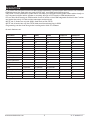
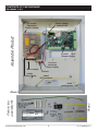
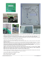
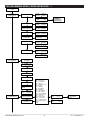
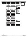
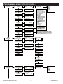
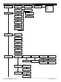
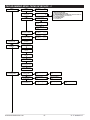
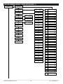
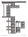
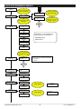
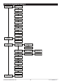
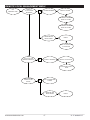
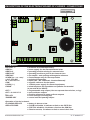
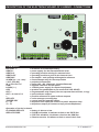
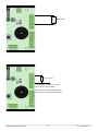
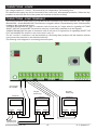
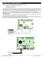
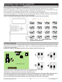
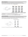
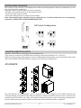
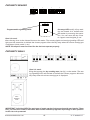
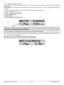
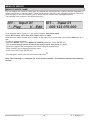
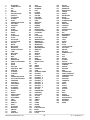
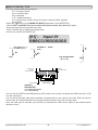
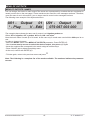
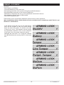
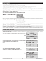
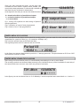
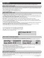
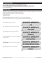
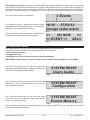
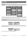
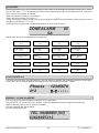
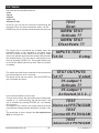

![[User manual] - KX_series_user_EN](http://vs1.manualzilla.com/store/data/005985322_1-73e2348e6003cbf1e0abe0da04f5dcec-150x150.png)